Disclosure of Invention
The invention aims to design a simple strap for charging, which is convenient to adjust the position of a charging coil, is suitable for various body shapes, is comfortable to wear and has low use cost.
The technical scheme of the invention is that the simple strap for charging comprises: the coil fixing part, the host fixing part, the connecting band and the transition band are arranged on the main body; the transition belts are respectively arranged at two ends of the connecting belt; the coil fixing part and the host fixing part are respectively connected with the transition belts at two ends of the connecting belt; and an anti-slip area with a friction coefficient of more than 0.2 with cotton cloth is arranged on the connecting belt and/or the transition belt.
Preferably, the width of the connecting belt is between 20 mm and 80 mm, and the length of the connecting belt is between 500 mm and 1000 mm; the width of the transition band is larger than that of the connecting band and smaller than that of the coil fixing part and/or the host fixing part, and the length of the transition band is 40-100 mm; the total length of the shoulder strap is 600 mm-1200 mm.
Preferably, the connecting band is provided with a strap pad; the back strap pad is detachable and is coated on the connecting strap through a nylon thread gluing; the back strap pad is a U-shaped pad after being coated; the strap pad is arranged on the connecting strap; the back strap pad is a U-shaped pad after being coated; the strap pad is provided with an anti-slip area with a cotton cloth friction coefficient of more than 0.2.
Preferably, the non-slip region is a non-slip glue array.
Preferably, the connecting belt is provided with a length adjusting mechanism.
Preferably, the connection band has a cable fixing unit thereon.
Preferably, the coil fixing part is a coil pocket, and the front surface of the coil fixing part is made of a breathable material; a first sealing part is arranged at the bag opening on the front side of the coil bag; the back of the coil pocket consists of single-layer mesh cloth with a net structure; the host fixing part is a host pocket, and the front surface of the host fixing part is made of breathable materials; a second sealing part is arranged at the bag opening on the front side of the host bag; the connecting belt is made of soft breathable materials; the transition belt is made of soft breathable materials; the back of the host pocket is connected with the soft breathable material used by the transition belt into a whole.
Preferably, the breathable material is a sandwich mesh; the soft breathable material is cotton cloth; the first sealing part and the second sealing part are elastic bands.
Preferably, the bottom of the coil pocket and the bottom of the host pocket are circular arc bottom edges; the total length of the simple charging harness is about 849 mm; the length of the coil pocket is about 115 mm, the width of the coil pocket is about 100 mm, and the radius of a circular arc at the bottom edge of the coil pocket is about 60 mm; the length of a transition zone between the coil pocket and the connecting belt is about 52 mm; the length of the host pocket is about 130 mm, the width of the host pocket is about 100 mm, and the radius of a circular arc at the bottom edge of the host pocket is about 120 mm; the length of a transition zone between the host pocket and the connecting belt is about 42 mm; the connecting band has a length of about 510 mm and a width of about 62 mm.
The invention also provides an in vitro wireless charging system for the implantable medical device, which comprises a charger host, a charging coil, a cable between the charger host and the charging coil, and the simple strap for charging according to any one of the technical schemes.
The simple strap for charging provided by the invention has the following advantages:
1. when the simple charging harness is used, the position of the charging coil is convenient to adjust, the coil fixing part provided with the charging coil is only required to be aligned to the position of the stimulator in the patient body, and the connecting band is wrapped around the neck of the patient, so that the position of the coil is very convenient to adjust, the simple charging harness can be used on the left side and the right side of the chest of the patient body, and is suitable for the position of the stimulator in the patient body;
2. the simple charging harness designed by the invention is simple and easy to use, can be used after being put on, can be suitable for different patient shapes, is more comfortable to wear, has small volume, is convenient to store and has low use cost.
Detailed Description
The present invention will be described in further detail with reference to the accompanying drawings.
Fig. 1 to 13 show a structure and a schematic use diagram of a simple harness for charging according to this embodiment.
As shown in FIGS. 1-5, typically, the implantable medical device 100 is implanted at a depth of about 1 cm below the precordial skin and is generally positioned parallel to the skin surface. The external charging device 200 generally includes a main charger 201 and an external charging coil 202, wherein the main charger 201 and the external charging coil 202 are connected by a cable 203, and wirelessly charge the implanted medical device in vivo by electromagnetic coupling.
When worn, the simple charging harness 300 of the present invention can dispose the external charging coil 202 of the implantable medical device in front of the left or right chest of the patient, corresponding to the position of the implantable medical device in the patient. When the external charging device charges the implantable medical device, the external charging coil 202 and the receiving coil of the implantable medical device are respectively located at opposite positions on both sides of the skin, and the axes of the external charging coil and the receiving coil are substantially aligned and parallel to the skin. The external charging coil 202 generates an oscillating electromagnetic field under the driving of the charger host 201, and the receiving coil of the internal implanted medical device can generate an induction current. The induced current can drive the implantable medical device to work after being rectified, filtered and the like, or charge an energy storage element in the implantable medical device.
Those skilled in the art will appreciate that the implantable medical device for performing a charging operation according to the present invention may be various types of devices implanted at a position in the chest of a human body and capable of delivering drugs, current signals, or sensing physiological states of the human body tissue, such as an implantable neurostimulator, an implantable cardiac pacemaker, an implantable cardiac defibrillator, an implantable drug pump, etc.
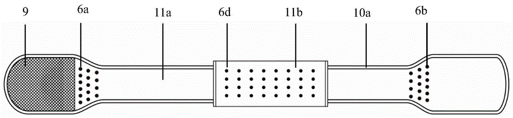
Fig. 6 to 8 further show the structure of the simple harness for charging of the present invention. In the present embodiment, the simple charging harness 300 includes a coil fixing portion 1, a main unit fixing portion 2, a connecting belt 3, a transition belt 4a, and a transition belt 4 b. Wherein, the transition zone 4a and the transition zone 4b are respectively arranged at two ends of the connecting belt 3; the coil fixing part 1 and the host fixing part 2 are respectively connected with a transition belt 4a and a transition belt 4 b; and the back of the connecting belt 3 and/or the transition belt 4a and the transition belt 4b is provided with anti-skid zones 6a,6b and 6c with the friction coefficient of cotton cloth being more than 0.2.
The coil fixing part 1 is generally designed in a shape to be adapted to a charging coil 202 of the external charging device. In a preferred embodiment, the coil fixing part 1 is provided as a substantially rectangular coil pocket having a circular arc at the bottom. The front side of the coil pocket is composed of sandwich mesh cloth 7a, so that the coil pocket is comfortable and breathable; an elastic band 8a is arranged at the bag opening on the front side and is used for hooping the bag opening to prevent the charging coil 202 from falling out; the back of the coil pocket is composed of single-layer mesh cloth 9, is light, thin and breathable and is used for being close to the implanted medical equipment. The sandwich mesh fabric 7a on the front side of the coil pocket and the single-layer mesh fabric 9 on the back side are connected through the binding edge 10a, and the single-layer mesh fabric 9 on the back side is connected with the transition belt 4a at the opening. In a preferred embodiment, the coil pocket has a length of about 115 mm, a width of about 100 mm, and a radius of the bottom arc of about 60 mm.
The host fixing section 2 is generally designed in a shape to be compatible with the charger host 201 of the external charging apparatus. In a preferred embodiment, the host holder 2 is configured as a substantially rectangular host pocket with a rounded bottom. The front side of the host pocket is composed of sandwich mesh cloth 7b, so that the host pocket is comfortable and breathable; an elastic band 8b is arranged at the front bag opening and is used for hooping the bag opening to prevent the charger host 201 from falling out; the back of the host pocket is connected with the material used by the transition belt 4b into a whole. In a preferred embodiment, the host pocket has a length of about 130 mm, a width of about 100 mm, and a radius of the bottom arc of about 120 mm.
The connecting belt 3, the transition belt 4a and the transition belt 4b are made of breathable cotton cloth 11a, and are soft and comfortable. In a preferred embodiment, the anti-slip zones 6a,6b,6c provided on the back of the connecting band 3 and/or the transition band 4a and the transition band 4b are an array of anti-slip glue. The width of the connecting band 3 is between 20 mm and 80 mm, the length is between 500 mm and 1000 mm, the width of the transition band 4a and the transition band 4b is larger than the width of the connecting band 3, smaller than the width of the coil fixing part 1 and/or the host fixing part 2, and the length is between 40 mm and 100 mm. In a preferred embodiment, the length of the interface tape 3 is about 510 mm, the width is about 62 mm, the length of the transition tape 4a is about 52 mm, and the length of the transition tape 4b is about 42 mm. In a variant embodiment, the connecting band 3 may also be provided with a length adjustment mechanism, such as a buckle, which allows the length of the connecting band to be adjusted to the size of the user.
The overall length of the simple charging harness 300 is set to a length corresponding to the implanted medical equipment at the subcutaneous position of the chest, and the overall length is 600 mm-1200 mm. In a preferred embodiment, the overall length of the simple charging harness 300 is about 849 mm.
Although the implantation position of the implantable medical device is a subcutaneous chest position in the present embodiment, it can be understood by those skilled in the art that the technical solution related to the present invention is not limited thereto, and the simple charging harness of the present invention can also be applied to implantable medical devices at any position under the abdomen and waist when the patient is in a stable sitting posture.
In a preferred embodiment, the simple charging harness 300 has a cover 10a around the periphery thereof for reinforcing the simple charging harness.
As shown in fig. 9, the simple charging harness coil pocket is placed at the chest position in the use state, and is basically in a state where the opening is upward, the arc-shaped side is downward, and the single-layer mesh fabric faces the human body. Such that the charging coil 202 outside the body can be easily inserted into the coil pocket. As shown in fig. 10, the host pocket in the use state is substantially in a state where the opening is upward and the arc edge is downward, so that the charger host 201 is inserted into the host pocket. The cable 203 between the charger main unit 201 and the charging coil 202 is typically placed along the connection band when in use. Also optionally, at least a portion of the cable 203 may be threaded from within the connection strap to provide for proper securement of the cable 203. In a preferred embodiment, the charging simple strap 300 is provided with a cable fixing member attached to the connection belt 3 and used for fixing a redundant cable with a fixed length, such as a velcro.
In a preferred embodiment, the connecting strip 3 is further provided with a harness pad 5, as shown in figures 6-8. The back strap pad 5 is composed of breathable cotton cloth 11b, is soft and comfortable, and is connected with the front side and the back side through wrapping edges 10 b. As shown in fig. 11 to 12, the back strap pad 5 is detachable and covered on the connection strap 3 by nylon fasteners 12a and 12 b. The inner side of the back belt cushion 5 is provided with an anti-skid area 6d with the friction coefficient of the cotton cloth being more than 0.2. The strap pad 5 is a U-shaped pad after being wrapped and is placed on the neck of the patient to increase the comfort when the patient wears the strap for charging. In addition, the harness pad 5 may be wrapped along with the redundant cable 203 to reduce the inconvenience of the redundant cable.
The simple charging harness 300 can arrange the external charging coil 202 of the implantable medical device on the left or right chest of the patient without being held by hand. When the simple charging harness 300 is worn and used, the coil fixing part 1 with the charging coil 202 is placed at a position corresponding to the patient-implanted medical device 100, and the main unit fixing part 2 with the charger main unit 201 is placed on the other side of the body around the neck via the connecting band 3. The chest of the person has an angle of inclination to the vertical that helps the coil pocket containing the coil 202 fit in position to align with the patient stimulator 100 in both normal sitting and standing positions. Since the strap 300 has a certain friction force with the clothes due to gravity, the friction force between the strap 300 and the clothes can be increased by the anti-slip region 6a provided in the connecting belt 3. In addition, because the weight of the charging coil 202 is close to that of the charger main unit 201, the weight of the two ends of the strap and the static friction force borne by the strap can reach a certain balance, and the coil 202 can be stabilized at a required height position. Likewise, in the case of using the back-strap pad 5, the anti-slip region 6c on the connection band 3 interacts with the back-strap pad 5 to prevent displacement between the back-strap pad 5 and the connection band 3; the anti-slip region 6d on the harness pad 5 interacts with clothing or skin to prevent displacement between the harness 300 and the patient. Furthermore, the anti-slip regions 6a and 6b disposed on the transition zone 4a and the transition zone 4b can prevent the position of the coil 202 from being relatively displaced after the patient slightly adjusts the posture, thereby facilitating the patient to slightly adjust the posture and relieving fatigue.
As shown in fig. 13, in a modified embodiment, the simple harness for charging may be used by being worn on the left shoulder or the right shoulder.
Although the front surface of the main unit pocket and the front surface of the coil pocket of the simple charging harness are made of sandwich mesh cloth in the above embodiments, it can be understood by those skilled in the art that the technical solution of the present invention is not limited thereto, and the front surfaces of the main unit pocket and the coil pocket of the simple charging harness may be selected from any suitable material having air permeability, such as nylon fabric, mixed fabric, and the like.
Although the connecting band, the transition band, and the back of the main unit pocket of the simple charging harness are made of cotton cloth in the above embodiments, it will be understood by those skilled in the art that the technical solution according to the present invention is not limited thereto, and the connecting band, the transition band, and the back of the main unit pocket of the simple charging harness may be selected from any suitable material having soft air permeability, such as cotton cloth, hemp cloth, and the like.
Although the coil pocket, the host pocket, the connecting band, the transition band and the back band pad are connected by wrapping in the above embodiments, it can be understood by those skilled in the art that the technical solution of the present invention is not limited thereto, and any suitable connecting and fixing means such as sewing, bonding and hot pressing may be used between the front and back parts of the coil pocket, the host pocket, the connecting band, the transition band and the back band pad.
Although the first and second sealing members are elastic bands in the above embodiments, it can be understood by those skilled in the art that the technical solution according to the present invention is not limited thereto, and the elastic member is provided to prevent the charging coil and the main unit from slipping out of the bag, so that other suitable members may be used to prevent the charging coil and the main unit from slipping out of the bag, such as velcro, zipper, buckle, snap ring, etc.
Although in the above embodiments, the coil fixing portion is a coil pocket, and the host fixing portion is a host pocket, it can be understood by those skilled in the art that the technical solution according to the present invention is not limited thereto, and the coil fixing portion is a housing for placing a coil, and the host fixing portion is for placing a charger host, so that a housing made of a material having a large friction coefficient with the clothes, such as a silicone shell adapted to the shape of the device, may be used for fixing.
This embodiment charge with simple and easy braces and adjust charging coil position convenient accuracy, simple easy-to-use, take promptly, can be suitable for different patient's bodily forms, wear comfortablely, small, accomodate conveniently, use cost is low.
Finally, it should be pointed out that: the above examples are only for illustrating the technical solutions of the present invention, and are not limited thereto. Although the present invention has been described in detail with reference to the foregoing embodiments, it will be understood by those of ordinary skill in the art that: the technical solutions described in the foregoing embodiments may still be modified, or some technical features may be equivalently replaced; and such modifications or substitutions do not depart from the spirit and scope of the corresponding technical solutions of the embodiments of the present invention.