CN1129162C - Cathode-ray tube - Google Patents
Cathode-ray tube Download PDFInfo
- Publication number
- CN1129162C CN1129162C CN99803877A CN99803877A CN1129162C CN 1129162 C CN1129162 C CN 1129162C CN 99803877 A CN99803877 A CN 99803877A CN 99803877 A CN99803877 A CN 99803877A CN 1129162 C CN1129162 C CN 1129162C
- Authority
- CN
- China
- Prior art keywords
- electron beam
- electrode
- lens
- electron
- voltage
- Prior art date
- Legal status (The legal status is an assumption and is not a legal conclusion. Google has not performed a legal analysis and makes no representation as to the accuracy of the status listed.)
- Expired - Fee Related
Links
Images





Classifications
-
- H—ELECTRICITY
- H01—ELECTRIC ELEMENTS
- H01J—ELECTRIC DISCHARGE TUBES OR DISCHARGE LAMPS
- H01J29/00—Details of cathode-ray tubes or of electron-beam tubes of the types covered by group H01J31/00
- H01J29/46—Arrangements of electrodes and associated parts for generating or controlling the ray or beam, e.g. electron-optical arrangement
- H01J29/48—Electron guns
-
- H—ELECTRICITY
- H01—ELECTRIC ELEMENTS
- H01J—ELECTRIC DISCHARGE TUBES OR DISCHARGE LAMPS
- H01J29/00—Details of cathode-ray tubes or of electron-beam tubes of the types covered by group H01J31/00
- H01J29/46—Arrangements of electrodes and associated parts for generating or controlling the ray or beam, e.g. electron-optical arrangement
- H01J29/48—Electron guns
- H01J29/488—Schematic arrangements of the electrodes for beam forming; Place and form of the elecrodes
-
- H—ELECTRICITY
- H01—ELECTRIC ELEMENTS
- H01J—ELECTRIC DISCHARGE TUBES OR DISCHARGE LAMPS
- H01J29/00—Details of cathode-ray tubes or of electron-beam tubes of the types covered by group H01J31/00
- H01J29/46—Arrangements of electrodes and associated parts for generating or controlling the ray or beam, e.g. electron-optical arrangement
- H01J29/48—Electron guns
- H01J29/50—Electron guns two or more guns in a single vacuum space, e.g. for plural-ray tube
- H01J29/503—Three or more guns, the axes of which lay in a common plane
-
- H—ELECTRICITY
- H01—ELECTRIC ELEMENTS
- H01J—ELECTRIC DISCHARGE TUBES OR DISCHARGE LAMPS
- H01J2229/00—Details of cathode ray tubes or electron beam tubes
- H01J2229/48—Electron guns
- H01J2229/4834—Electrical arrangements coupled to electrodes, e.g. potentials
- H01J2229/4837—Electrical arrangements coupled to electrodes, e.g. potentials characterised by the potentials applied
Landscapes
- Cathode-Ray Tubes And Fluorescent Screens For Display (AREA)
- Video Image Reproduction Devices For Color Tv Systems (AREA)
Abstract
Description
技术领域technical field
本发明涉及阴极射线管,尤其涉及安装画面周边析像度劣化小的电子枪构件的阴极射线管。The present invention relates to a cathode ray tube, and more particularly, to a cathode ray tube incorporating an electron gun member with less deterioration in resolution around a screen.
背景技术Background technique
自会聚式的一字排列型彩色显像管包含发射由经同一水平面的中央电子束及其两侧的一对侧电子束组成的一列配置的3束电子束的一字排列型电子枪构件、形成使电子枪构件发射的电子束偏转的非均匀磁场的偏转线圈。该电子枪构件发射的3束电子束,通过电子枪构件中所包含的主透镜部分的作用而会聚于屏幕中央,同时,通过由枕形水平偏转磁场和桶形垂直偏转磁场构成的非均匀磁场自会聚于画面全部区域。The self-converging in-line color picture tube includes an in-line electron gun component that emits three electron beams arranged in a row consisting of a central electron beam passing through the same horizontal plane and a pair of side electron beams on both sides, forming an electron gun. A deflection yoke for a non-uniform magnetic field that deflects the electron beam emitted by the member. The three electron beams emitted by the electron gun component converge at the center of the screen through the action of the main lens part contained in the electron gun component, and at the same time, self-converge through the non-uniform magnetic field composed of a pincushion-shaped horizontal deflection magnetic field and a barrel-shaped vertical deflection magnetic field. in the entire area of the screen.
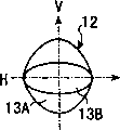
经过该非均匀磁场中的电子束6分别受到像散,例如如图1A所示,因枕形磁场10而受到箭头11H、11V方向的力。该电子束6在到达荧光屏周边时,如图1B所示,在荧光屏上形成的束斑12产生畸变。该畸变是由于电子束6在垂直方向即V轴方向过聚焦这种偏转像差而产生的。The electron beams 6 passing through this non-uniform magnetic field are respectively subjected to astigmatism, for example, as shown in FIG. 1A , they are subjected to forces in the directions of
由此,束斑12形成垂直方向宽的晕部13A和水平方向即H轴方向延伸的芯部13B。管子越大型或管子偏转角越大,这种偏转像差越大,从而荧光屏周边部析像度显著恶化。Thus, the
为了解决这种因偏转像差产生的析像度劣化,开发了一种高性能的电子枪构件,它根据荧光屏周边部电子束偏转,使电子枪构件中形成的电子透镜的部分透镜作用变化,从而修正荧光屏周边部的偏转像差。In order to solve the resolution degradation caused by deflection aberration, a high-performance electron gun component has been developed, which changes part of the lens action of the electron lens formed in the electron gun component according to the deflection of the electron beam at the periphery of the fluorescent screen, thereby correcting Deflection aberration at the periphery of the fluorescent screen.
作为一个例子,在特开昭64-38947号公报中记载了下述电子枪构件。如图2所示,该电子枪构件具有从阴极K(R、G、B)侧向荧光屏侧顺次配置的第1栅极G1、第2栅极G2、第3栅极G3、第4栅极G4、第5栅极G5、第1中间电极GM1、第2中间电极GM2、第6栅极G6。向这些第3至第6栅极分别施加图3所示的电压。As an example, the following electron gun components are described in JP-A-64-38947. As shown in FIG. 2, the electron gun assembly has a first grid G1, a second grid G2, a third grid G3, and a fourth grid arranged sequentially from the cathode K (R, G, B) side to the fluorescent screen side. G4, the fifth grid G5, the first intermediate electrode GM1, the second intermediate electrode GM2, and the sixth grid G6. The voltages shown in FIG. 3 are applied to these third to sixth gates, respectively.
在图3中,图中实线表示电子束聚焦于荧光屏中央即无偏转时的电压,图中虚线表示电子束聚焦于荧光屏周边部即有偏转时的电压。横轴Z对应于电子枪构件配置的圆筒状管颈部实际中心轴相当的管轴(即Z轴)上的各电极位置。Z轴正方向对应于荧光屏侧,Z轴负方向对应于阴极侧。纵轴V表示向各栅极施加的电压电平。In Fig. 3, the solid line in the figure represents the voltage when the electron beam is focused on the center of the phosphor screen, that is, there is no deflection, and the dotted line in the figure represents the voltage when the electron beam is focused on the periphery of the phosphor screen, that is, there is deflection. The horizontal axis Z corresponds to the position of each electrode on the tube axis (namely the Z axis) corresponding to the actual central axis of the cylindrical tube neck of the electron gun component configuration. The positive direction of the Z axis corresponds to the fluorescent screen side, and the negative direction of the Z axis corresponds to the cathode side. The vertical axis V represents the voltage level applied to each gate.
如图3所示,向第3栅极和第5栅极施加动态聚焦电压,该电压是在预定直流电压Vf上叠加根据电子束偏转量而变化的变化电压Vd.As shown in Figure 3, a dynamic focus voltage is applied to the third grid and the fifth grid, which is a predetermined DC voltage Vf superimposed on a variable voltage Vd that changes according to the amount of deflection of the electron beam.
通过把这种电压施加于各栅极,如图4A和4B所示,在第5栅极G5与第1中间电极GM1之间、第1中间电极GM1与第2中间电极GM2之间、在第2中间电极GM2与第6栅极G6之间分别形成四极子透镜部QL2、圆筒透镜部CL、四极子透镜部QL1。四极子透镜部QL2具有相对会聚作用的垂直方向分量与相对发散作用的水平方向分量。四极子透镜部QL1具有相对发散作用的垂直方向分量和相对分聚作用的水平方向分量。电子枪构件的主电子透镜部ML由这种四极子透镜部QL1、QL2和圆筒透镜部CL构成。By applying this voltage to each grid, as shown in FIGS. 4A and 4B, between the fifth grid G5 and the first intermediate electrode GM1, between the first intermediate electrode GM1 and the second intermediate electrode GM2, and between the fifth grid G5 and the first intermediate electrode GM1, 2 Between the intermediate electrode GM2 and the sixth grid G6, a quadrupole lens portion QL2, a cylindrical lens portion CL, and a quadrupole lens portion QL1 are respectively formed. The quadrupole lens portion QL2 has a vertical direction component that acts on relative convergence and a horizontal component that acts on relative divergence. The quadrupole lens portion QL1 has a vertical component relative to divergence and a horizontal component relative to divergence. The main electron lens portion ML of the electron gun unit is composed of such quadrupole lens portions QL1 and QL2 and the cylindrical lens portion CL.
如图3所示,偏转时,使加至第3栅极G3和第5栅极G5的电压从实线起如虚线所示升高,由此,如图4B所示,其构成使四极子透镜部QL2和圆筒透镜部CL减弱,水平方向会聚力不变,垂直方向仅保持发散作用,从而修正偏转磁场引起的垂直方向的电子束过聚焦。As shown in FIG. 3, during deflection, the voltage applied to the third grid G3 and the fifth grid G5 is raised from the solid line as shown by the dotted line, thus, as shown in FIG. 4B, the quadrupole The lens portion QL2 and the cylindrical lens portion CL are weakened, the convergence in the horizontal direction remains unchanged, and only the divergence in the vertical direction is maintained, thereby correcting the overfocusing of the electron beams in the vertical direction caused by the deflection magnetic field.
但是,与水平方向偏转磁场同步的动态聚焦电压与15KHz以上的偏转频率同步,因而在这种场合,经第5栅极与第1中间电极间、第1中间电极与第2中间电极间、第2中间电极与第6栅极间的静电电容传送交流分量,在第1和第2中间电极上与部分水平方向动态聚焦电压叠加。由此,不仅四极子透镜部QL2部及圆筒透镜部CL,而且四极子透镜部QL1,其透镜作用都变动。However, the dynamic focus voltage synchronous with the deflection magnetic field in the horizontal direction is synchronous with the deflection frequency above 15KHz, so in this case, through between the fifth grid and the first intermediate electrode, between the first intermediate electrode and the second intermediate electrode, between the first intermediate electrode and the second intermediate electrode, 2. The electrostatic capacitance between the middle electrode and the sixth grid transmits the AC component, which is superimposed with part of the horizontal dynamic focus voltage on the first and second middle electrodes. Accordingly, not only the quadrupole lens portion QL2 and the cylindrical lens portion CL but also the quadrupole lens portion QL1 have varying lens actions.
因而,垂直方向的发散作用不足,而在自会聚型中,会聚力不变的水平方向会聚力变弱。于是,在荧光屏周边部形成保留垂直方向过聚焦的晕部、在水平方向会聚力不足的电子束束斑。Therefore, the diverging effect in the vertical direction is insufficient, and in the self-converging type, the converging force in the horizontal direction, which does not change the converging force, becomes weak. As a result, an electron beam spot with an insufficient concentration in the horizontal direction and a halo portion which remains overfocused in the vertical direction is formed on the peripheral portion of the fluorescent screen.
为了解决上述问题,在特开平7-147146号公报中记载了图5所示的电子枪构件。第5栅极由第1段G51和第2段G52构成。在第3栅极和第2段G52上施加如图6虚线所示随电子束编转量增大而升高的电压。由此,如图7虚线所示,仅在偏转时,在第1段G51与第2段G52间形成具发散作用的垂直方向分量与具会聚作用的水平方向分量的四极子透镜部QL3。In order to solve the above problems, Japanese Unexamined Patent Publication No. 7-147146 discloses an electron gun assembly shown in FIG. 5 . The fifth grid consists of a first segment G51 and a second segment G52. A voltage that increases as the amount of rotation of the electron beam increases is applied to the third grid and the second segment G52 as shown by the dotted line in FIG. 6 . Thus, as shown by the dashed line in FIG. 7 , a quadrupole lens portion QL3 having a diverging vertical component and a converging horizontal component is formed between the first segment G51 and the second segment G52 only during deflection.
但是,在如上所述使辅助四极子透镜QL3起作用时,存在透镜主面,即电子束聚焦于荧光屏时的假想透镜中心(从阴极发射的电子束轨道与入射至荧光屏的电子束轨道的交叉点)移动的问题。However, when the auxiliary quadrupole lens QL3 is made to function as described above, there is a lens main surface, that is, a virtual lens center when the electron beam is focused on the phosphor screen (the distance between the orbit of the electron beam emitted from the cathode and the orbit of the electron beam incident on the phosphor screen) intersection) problem of movement.
垂直方向的透镜主面,在不偏转时,大致位于主透镜部ML的中央。与此相对,在四极子透镜部QL3起作用而偏转时,因四极子透镜部QL3的垂直方向分量而使电子束在垂直方向发散,从而垂直方向透镜主面,也从主透镜部ML在荧光屏侧即Z轴正方向移动。The main lens surface in the vertical direction is located approximately at the center of the main lens portion ML when not deflected. On the other hand, when the quadrupole lens part QL3 functions to deflect, the electron beam is diverged in the vertical direction due to the vertical direction component of the quadrupole lens part QL3, so that the main surface of the lens in the vertical direction is also transmitted from the main lens part ML. Move in the positive direction of the Z-axis on the fluorescent screen side.
水平方向的透镜主面,在不偏转时,与垂直方向同样,大致位于主透镜部ML的中央。与此相对,在四极子透镜部QL3起作用而偏转时,由四极子透镜部QL3的水平方向分量聚焦电子束,从而水平方向的透镜主面也从主透镜部ML移动至阴极侧,即移动至Z轴负方向。The main lens surface in the horizontal direction is located approximately at the center of the main lens portion ML when not deflected, as in the vertical direction. On the other hand, when the quadrupole lens part QL3 acts and deflects, the electron beam is focused by the horizontal direction component of the quadrupole lens part QL3, and the lens main surface in the horizontal direction also moves from the main lens part ML to the cathode side, That is, move to the negative direction of the Z axis.
由于这种透镜主面的移动,在偏转的电子束聚焦的荧光屏周边部上,垂直方向的角放大率相对于水平方向的角放大率为小。因而,电子束的束斑形状,除偏转线圈的偏转磁场的影响外,还受到水平方向相对于垂直方向扩大的横向拉长的畸变作用。Due to this movement of the principal surface of the lens, the angular magnification in the vertical direction is small relative to the angular magnification in the horizontal direction at the peripheral portion of the phosphor screen where the deflected electron beams are focused. Therefore, in addition to the influence of the deflection magnetic field of the deflection yoke, the beam spot shape of the electron beam is also distorted by the lateral elongation that expands in the horizontal direction relative to the vertical direction.
因而,在荧光屏周边部上,束斑形状的水平方向直径更加扩大,引起图像劣化。而且,束斑形状的垂直方向直径更加缩小,在周边部还有产生波纹的问题。Therefore, the diameter of the beam spot shape in the horizontal direction is further enlarged in the peripheral portion of the fluorescent screen, causing image degradation. Furthermore, the diameter of the beam spot shape in the vertical direction is further reduced, and there is a problem of moiré in the peripheral portion.
在偏转角大的彩色阴极射线管的场合,偏转磁场中具有芯部像差成分,偏转磁场的透镜作用分量不同,即偏转线圈透镜分别对侧电子束的聚焦力不同,从而如图14所示,产生画面左、右中电子束斑径向形状显著不同的现象。这时,即使向聚焦电极施加适当的动态电压,也会产生在画面左右电子束斑不能同时适当聚焦的问题。In the case of a color cathode ray tube with a large deflection angle, there is a core aberration component in the deflection magnetic field, and the lens action components of the deflection magnetic field are different, that is, the focusing forces of the deflection coil lenses on the opposite side electron beams are different, so as shown in Figure 14 , resulting in the phenomenon that the radial shape of the electron beam spot in the left and right of the picture is significantly different. At this time, even if an appropriate dynamic voltage is applied to the focusing electrodes, there is a problem that the electron beam spots on the left and right sides of the screen cannot be properly focused at the same time.
如上所述,在特开昭64-38947号公报的电子枪构件中,经构成主透镜部ML的各电极间的静电电容,把加至第5栅极G5的动态聚焦电压的交流分量传送至第1和第2中间电极。为此,在第2中间电极与第6栅极之间形成的四极子透镜部QL1的透镜作用也会变动。因而,垂直方向的发散作用与水平方向的聚焦力不足,在荧光屏周边部留有垂直方向过聚焦引起的晕部,同时水平方向聚焦力不足,电子束斑畸变使得水平方向扩张。As described above, in the electron gun structure of JP-A-64-38947, the AC component of the dynamic focus voltage applied to the fifth grid G5 is transmitted to the first grid through the capacitance between the electrodes constituting the main lens portion ML. 1 and 2 middle electrodes. For this reason, the lens action of the quadrupole lens portion QL1 formed between the second intermediate electrode and the sixth grid electrode also varies. Therefore, the divergence in the vertical direction and the focusing power in the horizontal direction are insufficient, leaving halos caused by over-focusing in the vertical direction on the periphery of the fluorescent screen, and the focusing power in the horizontal direction is insufficient, and the distortion of the electron beam spot makes the horizontal direction expand.
为解决上述现象,在特开平7-147146号公报所述的电子枪构件中,仅在偏转时,在主透镜部ML的阴极侧形成辅助四极子透镜QL3。使该四极子透镜部QL3偏转时产生作用,则垂直方向的透镜主面前进至荧光屏侧,水平方向的透镜主面后退至阴极侧。由此,在垂直方向和水平方向间产生透镜倍率差,从而产生形成水平方向拉长的畸变电子束斑的问题。In order to solve the above phenomenon, in the electron gun assembly disclosed in JP-A-7-147146, an auxiliary quadrupole lens QL3 is formed on the cathode side of the main lens portion ML only during deflection. When the quadrupole lens portion QL3 is deflected, the principal surface of the lens in the vertical direction advances toward the fluorescent screen, and the principal surface of the lens in the horizontal direction retreats toward the cathode side. As a result, there is a difference in lens magnification between the vertical direction and the horizontal direction, resulting in the formation of a distorted electron beam spot elongated in the horizontal direction.
在偏转角大的彩色阴极射线管的场合,偏转磁场中具有芯像差成分,偏转磁场透镜作用分量不同,即偏转线圈分别对侧电子束的聚焦力有差异,从而如图14所示,产生在画面左、右电子束斑径向形状有显著差异的现象。这时,即使向聚焦电极施加适当的动态电压,也会产生画面左右电子束斑不能同时适当聚焦的问题。In the case of a color cathode ray tube with a large deflection angle, there is a core aberration component in the deflection magnetic field, and the lens action component of the deflection magnetic field is different, that is, the focusing power of the deflection coils on the side electron beams is different, so as shown in Fig. 14, There is a significant difference in the radial shape of the left and right electron beam spots on the screen. At this time, even if an appropriate dynamic voltage is applied to the focusing electrodes, there will be a problem that the electron beam spots on the left and right sides of the screen cannot be properly focused at the same time.
发明内容Contents of the invention
本发明为解决上述问题而作出,其目的在于提供一种通过解决或减轻画面周边部产生的电子束斑形状的畸变现象,在画面整个区域可得到良好析像度的阴极射线管。The present invention has been made to solve the above problems, and an object of the present invention is to provide a cathode ray tube capable of obtaining good resolution in the entire area of the screen by solving or reducing the distortion of the electron beam spot shape generated in the peripheral portion of the screen.
如前所述,水平方向透镜主面向阴极侧后退、垂直方向透镜主面向荧光屏侧前进的电子束水平方向和垂直方向角放大率差造成的横向拉长化,可以说是第3四极子透镜QL3强度越大,则角放大率的差越大。这是因为水平方向和垂直方向透镜主面的移动量受第3四极子透镜QL3的聚焦和发散透镜作用的影响。该第3四极子透镜QL3的透镜作用,如前所述,是用于弥补向主透镜部的中间电极GM1和GM2叠加动态电压的交流分量而引起的垂直方向发散作用及水平方向聚焦作用的不足。因而,若减少向中间电极叠加动态电压,则第3四极子透镜QL3的透镜作用弱也可以。这相当于水平方向和垂直方向透镜主面的移动量变小,是减轻画面周边电子束斑点角放大率差引起的横向拉长化的方向。As mentioned above, the lateral elongation caused by the difference in angular magnification between the horizontal direction and the vertical direction of the electron beam caused by the main surface of the lens in the horizontal direction receding to the cathode side and the main surface of the lens in the vertical direction advancing to the phosphor screen side can be said to be the third quadrupole lens The greater the QL3 intensity, the greater the difference in angular magnification. This is because the amount of movement of the lens main surface in the horizontal direction and the vertical direction is affected by the focusing and diverging lens actions of the third quadrupole lens QL3. The lens action of the third quadrupole lens QL3 is to compensate for the divergence action in the vertical direction and the focusing action in the horizontal direction caused by superimposing the AC component of the dynamic voltage on the intermediate electrodes GM1 and GM2 of the main lens part as described above. insufficient. Therefore, the lens action of the third quadrupole lens QL3 may be weak if the superimposition of the dynamic voltage on the intermediate electrode is reduced. This corresponds to a reduction in the amount of movement of the main surface of the lens in the horizontal direction and the vertical direction, and is a direction to reduce the lateral elongation caused by the difference in angular magnification of the electron beam spot around the screen.
于是,如果减少动态电压向中间电极GM1和GM2的重叠,则可减轻画面周边电子束的横向拉长化。Therefore, if the overlapping of the dynamic voltage on the intermediate electrodes GM1 and GM2 is reduced, the lateral elongation of the electron beams around the screen can be reduced.
在本发明中,作为减少向中间电极GM1和GM2叠加动态电压的手段,制成下述构成。In the present invention, as means for reducing superimposition of dynamic voltages on the intermediate electrodes GM1 and GM2, the following configurations are employed.
图9A示出用于本发明阴极射线管的电子枪构件的主透镜部的电极构成和接线,图9B表示图9A所示的主透镜部的等效电路。FIG. 9A shows the electrode configuration and wiring of the main lens unit used in the electron gun assembly of the cathode ray tube of the present invention, and FIG. 9B shows an equivalent circuit of the main lens unit shown in FIG. 9A.
在施加与偏转磁场同步变动的中等聚焦电压的聚焦电极G5与施加阳极电压的第1阳极电极G61之间配置一个中间电极GM,提供比中等聚焦电压高、比阳极电压低的电压。由这三个电极形成电场扩张型的主透镜部ML。在形成该电场扩张型的主透镜部ML的第1阳极电极G61与配置在比第1阳极电极在电子束行进方向靠近荧光屏侧的、施加相同阳极电压的第2阳极电极G63之间,至少配置一个辅助电极G62,该电极62与中间电极GM电气连接。A middle electrode GM is disposed between the focus electrode G5 applied with a medium focus voltage which varies synchronously with the deflection magnetic field, and the first anode electrode G61 applied with an anode voltage, and a voltage higher than the medium focus voltage and lower than the anode voltage is provided. These three electrodes form an electric field expansion type main lens portion ML. Between the first anode electrode G61 forming the main lens portion ML of the electric field expansion type and the second anode electrode G63 arranged on the phosphor screen side in the electron beam traveling direction than the first anode electrode and applied with the same anode voltage, at least An auxiliary electrode G62 electrically connected to the intermediate electrode GM.
以上为简化说明,对于中间电极GM为一个的情况进行说明,但不限于此,不言而喻,中间电极也可有多个。而且,虽然该电极构成图中没有表示,但是聚焦电极G5的阴极侧存在第3四极子透镜QL3。In the above, for the sake of simplification, the case where there is one intermediate electrode GM has been described, but the present invention is not limited thereto, and it goes without saying that there may be a plurality of intermediate electrodes. Furthermore, although this electrode configuration is not shown in the drawing, there is a third quadrupole lens QL3 on the cathode side of the focusing electrode G5.
示于图10A的以往的电极构成,其等效电路示于图10B,叠加至中间电极GM的电压Vm,如设动态电压的交流分量为Vd,则由示于图10B的等效电路可计算Vm=c/2c·Vd-1/2·Vd,因而在中间电极GM上叠加聚焦电极G5所加交流分量Vd的50%(聚焦电极G5与中间电极GM间及中间电极GM与阳极电极G6间的静电电容相同的情况下)。与此相对,在本发明的构成中,电极构成如图9A所示,等效电路如图9B所示。这时,向中间电极GM叠加的电压Vm,可计算为Vm=c/4c·Vd=1/4Vd,因而在中间电极GM上叠加聚焦电极G5所加交流分量Vd的25%。因而,通过本发明的构成,可使以往叠加50%的电压减半为25%。The equivalent circuit of the conventional electrode configuration shown in FIG. 10A is shown in FIG. 10B. The voltage Vm superimposed on the middle electrode GM, if the AC component of the dynamic voltage is Vd, can be calculated from the equivalent circuit shown in FIG. 10B Vm=c/2c·Vd-1/2·Vd, thus 50% of the AC component Vd applied by the focusing electrode G5 is superimposed on the intermediate electrode GM (between the focusing electrode G5 and the intermediate electrode GM and between the intermediate electrode GM and the anode electrode G6 In the case of the same electrostatic capacitance). In contrast, in the configuration of the present invention, the electrode configuration is as shown in FIG. 9A, and the equivalent circuit is as shown in FIG. 9B. At this time, the voltage Vm superimposed on the intermediate electrode GM can be calculated as Vm=c/4c·Vd=1/4Vd, so 25% of the AC component Vd applied by the focusing electrode G5 is superimposed on the intermediate electrode GM. Therefore, according to the configuration of the present invention, the conventional superimposed voltage of 50% can be halved to 25%.
以往因动态电压交流分量50%叠加至主透镜部的中间电极GM,从而产生垂直方向发散作用不足及水平方向聚焦作用不足。用于对此进行弥补的第3四极子透镜QL3的动作产生水平方向透镜主面向阴极侧后退、垂直方向透镜主面向荧光屏侧前进,从而引起电子束水平方向和垂直方向角放大率差,由此产生的横向拉长化通过上述可减半。In the past, 50% of the AC component of the dynamic voltage is superimposed on the middle electrode GM of the main lens portion, resulting in insufficient divergence in the vertical direction and insufficient focusing in the horizontal direction. The movement of the third quadrupole lens QL3 to compensate for this causes the principal surface of the lens in the horizontal direction to recede toward the cathode side, and the principal surface of the lens in the vertical direction to advance toward the fluorescent screen side, thereby causing a difference in angular magnification between the horizontal direction and the vertical direction of the electron beam. The resulting transverse elongation can be halved by the above.
如图11B所示,在形成电场扩张型的主透镜部的第1阳极电极G61、配置在比第1阳极电极在电子束行进方向靠近荧光屏侧且施加相同阳极电压的第2阳极电极G63,以及与配置在上述两阳极电极之间的中间电极GM电气连接的辅助电极G62之间,形成相对具有垂直方向发散、水平方向聚焦的透镜作用的非对称透镜,配置在偏转磁场的DY透镜附近。As shown in FIG. 11B , the first anode electrode G61 forming the main lens portion of the electric field expansion type, the second anode electrode G63 arranged on the fluorescent screen side in the electron beam traveling direction than the first anode electrode and applying the same anode voltage, and Between the auxiliary electrode G62 electrically connected to the intermediate electrode GM arranged between the two anode electrodes, an asymmetric lens having a lens function of diverging in the vertical direction and focusing in the horizontal direction is formed, and is arranged near the DY lens of the deflection magnetic field.
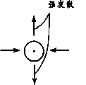
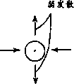
在图13A中示出在DY透镜附近配置像散透镜时的透镜状态和电子束轨道,在图13B中示出在离开DY透镜的位置配置像散透镜时的透镜状态和电子束轨道。其中αo是从电子束形成部的出射角,αi(V)及αi(H)表示射至荧光屏的入射角,LV和LH分别表示垂直方向(V)和水平方向(H)的透镜主面位置。在电子束出射角αo相同时,该透镜主面位置位于阴极侧一方时射至荧光屏的电子束入射角变小,角放大率变大。为此,投影至荧光屏的电子束束斑变大。反之,在该透镜主面位置位于荧光屏时,角放大率变小,电子束束斑也变小。FIG. 13A shows the lens state and the electron beam trajectory when the astigmatic lens is arranged near the DY lens, and FIG. 13B shows the lens state and the electron beam trajectory when the astigmatic lens is arranged away from the DY lens. Where αo is the exit angle from the electron beam forming part, αi(V) and αi(H) represent the incident angles to the phosphor screen, LV and LH represent the positions of the principal surface of the lens in the vertical direction (V) and the horizontal direction (H), respectively . When the electron beam exit angle αo is the same, when the position of the main surface of the lens is on the cathode side, the incident angle of the electron beam to the fluorescent screen becomes smaller, and the angular magnification becomes larger. For this reason, the electron beam spot projected onto the phosphor screen becomes larger. Conversely, when the position of the main surface of the lens is located on the phosphor screen, the angular magnification becomes smaller and the beam spot of the electron beam becomes smaller.
如图13A所示的DY透镜附近配置像散透镜时,若与如图13B所示的在离开DY透镜位置处配置像散透镜的情况比较,如图13A所示,在DY透镜附近配置像散透镜时,像散透镜与DY透镜的合成透镜的主面,在垂直方向(V)位于DY透镜稍向荧光屏侧(LV),在水平方向(H),位于像散透镜稍向阴极侧(LH),水平方向电子束直径比垂直方向电子束直径大。如图13B所示的场合那样,在离开DY透镜的位置配置像散透镜时,该现象变得更显著,垂直方向(V)主面位置(LV′)虽然不怎么变化,但水平方向的主面位置(LH′)大大移向阴极侧,电子束束斑水平方向电子束直径变得更大。这样,通过在DY透镜附近配置像散透镜,与在离开DY透镜位置配置像散透镜相比,画面周边电子束束斑形状可变得更圆。When the astigmatic lens is arranged near the DY lens as shown in FIG. In the case of a lens, the main surface of the synthetic lens of the astigmatic lens and the DY lens is located in the vertical direction (V) on the side of the DY lens slightly toward the fluorescent screen (LV), and in the horizontal direction (H) on the side of the astigmatic lens slightly toward the cathode (LH ), the diameter of the electron beam in the horizontal direction is larger than that in the vertical direction. As in the case shown in FIG. 13B , when an astigmatic lens is placed away from the DY lens, this phenomenon becomes more remarkable. Although the position (LV') of the main surface in the vertical direction (V) does not change much, the position of the main surface in the horizontal direction (V) does not change much. The surface position (LH') is greatly shifted toward the cathode side, and the electron beam diameter in the horizontal direction of the electron beam spot becomes larger. Thus, by arranging the astigmatic lens near the DY lens, the electron beam spot shape around the screen can be made more circular than when the astigmatic lens is arranged away from the DY lens.
如上所述,通过减少向构成主透镜部的中间电极叠加动态电压的效果,及在DY透镜附近形成相对具有垂直方向发散作用、水平方向聚焦作用的非对称透镜,可减轻画面周边电子束束斑的过渡横塌现象(垂直直径过分缩小和水平直径过分扩大)。As mentioned above, by reducing the effect of superimposing dynamic voltage on the intermediate electrode constituting the main lens part, and forming an asymmetric lens with a relatively vertical divergence effect and a horizontal direction focus effect near the DY lens, the electron beam spot around the screen can be reduced Transition slump phenomenon (excessive reduction of vertical diameter and excessive expansion of horizontal diameter).
为了解决上述课题,达到上述目的,根据本发明一个方面,提供一种阴极射线管,它包括具有形成并射出至少1束电子束的电子束形成部、加速该电子束并使之聚焦于画面上的主电子透镜部的电子枪构件;产生用于偏转从所述电子枪构件发射的电子束并在画面水平方向及垂直方向扫描的偏转磁场的偏转线圈;所述主电子透镜部是电场扩张型透镜,它由施加第1电平的聚焦电压的聚焦电极、施加比第1电平高的第2电平的阳极电压的阳极电极、配置在所述聚焦电极与阳极电极间并施加比所述第1电平高且比第2电平低的第3电平的中间电压的至少一个中间电极构成;所述阳极电极具有第1阳极电极、配置在比该第1阳极电极更靠近电子束行进方向的所述画面侧的第2阳极电极、配置在所述第1阳极电极与第2阳极电极间的至少一个辅助电极;至少一个所述辅助电极与所述中间电极的至少一个电气连接。In order to solve the above-mentioned problems and achieve the above-mentioned object, according to one aspect of the present invention, a cathode ray tube is provided, which includes an electron beam forming part that forms and emits at least one electron beam, accelerates the electron beam and focuses it on the screen. An electron gun member of the main electron lens part; a deflection coil for deflecting an electron beam emitted from the electron gun member and scanning a deflection magnetic field in the horizontal direction and the vertical direction of the screen; the main electron lens part is an electric field expansion type lens, It consists of a focusing electrode applying a focusing voltage of the first level, an anode electrode applying an anode voltage of a second level higher than the first level, arranged between the focusing electrode and the anode electrode and applying a voltage higher than the first level. at least one intermediate electrode with a third level intermediate voltage that is higher in level and lower than the second level; The second anode electrode on the screen side, at least one auxiliary electrode disposed between the first anode electrode and the second anode electrode; at least one auxiliary electrode is electrically connected to at least one of the intermediate electrodes.
附图说明Description of drawings
图1A和图1B是用于说明荧光屏周边部形成的电子束束斑畸变的图。1A and 1B are diagrams for explaining distortion of electron beam spots formed in the peripheral portion of a phosphor screen.
图2是例示以往电子枪构件的概略水平剖面图。Fig. 2 is a schematic horizontal sectional view illustrating a conventional electron gun component.
图3是加至图2所示电子枪构件主要栅极的电压电平的概略示图。FIG. 3 is a schematic diagram of the voltage levels applied to the main grids of the electron gun assembly shown in FIG. 2. FIG.
图4A和图4B是偏转及无偏转时主电子透镜部透镜作用的说明图。4A and 4B are explanatory diagrams of the lens action of the main electron lens section when deflected and not deflected.
图5是以往电子枪构件另一例子的概略水平剖面图。Fig. 5 is a schematic horizontal sectional view of another example of conventional electron gun components.
图6是加至图5所示电子枪构件的主要栅极的电压电平的概略示图。FIG. 6 is a schematic diagram of voltage levels applied to the main grids of the electron gun assembly shown in FIG. 5. FIG.
图7是偏转和无偏转时主电子透镜部透镜作用的说明图。Fig. 7 is an explanatory view of the lens action of the main electron lens section when deflected and not deflected.
图8是作为本发明阴极射线管一个例子的彩色阴极射线管构造的概略水平剖面图。Fig. 8 is a schematic horizontal sectional view showing the structure of a color cathode ray tube as an example of the cathode ray tube of the present invention.
图9A是本发明电子枪构件的主电子透镜部构成的概略示图,图9B是图9A所示主电子透镜部等效电路图。Fig. 9A is a schematic diagram showing the structure of the main electron lens part of the electron gun assembly of the present invention, and Fig. 9B is an equivalent circuit diagram of the main electron lens part shown in Fig. 9A.
图10A是以往电子枪构件的主电子透镜部构成的概略示图,图10B是图10A所示主电子透镜部的等效电路图。FIG. 10A is a schematic diagram showing the configuration of a main electron lens portion of a conventional electron gun unit, and FIG. 10B is an equivalent circuit diagram of the main electron lens portion shown in FIG. 10A .
图11A是用于图8所示的彩色阴极射线管的电子枪构件构成的概略垂直剖面图,图11B是图11A所示电子枪构件透镜作用的说明图。Fig. 11A is a schematic vertical sectional view showing the configuration of an electron gun component used in the color cathode ray tube shown in Fig. 8, and Fig. 11B is an explanatory diagram illustrating the operation of a lens of the electron gun component shown in Fig. 11A.
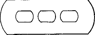
图12A至12E是构成图11A所示电子枪构件的主电子透镜部的各电极构造的正视图。12A to 12E are front views showing the configuration of electrodes constituting the main electron lens portion of the electron gun assembly shown in FIG. 11A.
图13A和13B是DY透镜和像散透镜的位置关系及放大率关系的说明图。13A and 13B are explanatory views of the positional relationship and the magnification relationship of the DY lens and the astigmatic lens.
图14是侧电子束(R)轨道在偏转磁场中的位置和画面周边电子束束斑形状示图。Fig. 14 is a diagram showing the position of the orbit of the side electron beam (R) in the deflection magnetic field and the shape of the electron beam spot around the screen.
图15A是侧电子束(R)在通过图14中(A)所示的轨道时与第2阳极电极的辅助电极侧的电子束通过孔的位置关系示图,图15B是侧电子束(R)在通过图14中(B)所示轨道时与第2阳极电极的辅助电极侧的电子束通过孔的位置关系示图,图15C是图15A所示场合接受侧电子束(R)的透镜作用的概略示图,图15D是图15B所示场合接受侧电子束(R)的透镜作用的概略示图。Fig. 15A is a side electron beam (R) when passing through the orbit shown in Fig. 14 (A) and the electron beam passing hole of the auxiliary electrode side of the 2nd anode electrode The positional relationship diagram, Fig. 15B is the side electron beam (R ) when passing through the track shown in (B) in Figure 14 and the positional relationship between the electron beam passing hole on the auxiliary electrode side of the second anode electrode, and Figure 15C is the lens for receiving the electron beam (R) on the side shown in Figure 15A As a schematic diagram of the action, Fig. 15D is a schematic diagram of the lens action of the electron beam (R) on the receiving side in the case shown in Fig. 15B.
图16是本发明第3实施例中有接受侧电子束可能性的主透镜部受到彗形像差时从荧光屏侧所视电子束束斑的图。Fig. 16 is a diagram showing electron beam spots viewed from the fluorescent screen side when the main lens portion which may receive electron beams in the third embodiment of the present invention receives coma aberration.
具体实施方式Detailed ways
下文,参照附图说明本发明阴极射线管的一实施形态。Hereinafter, an embodiment of a cathode ray tube according to the present invention will be described with reference to the drawings.
首先,对本发明第1实施形态加以说明。First, a first embodiment of the present invention will be described.
图9A表示用于本发明阴极射线管的电子枪构件的主透镜部的电极构成和接线,图9B表示图9A所示主透镜部的等效电路。Fig. 9A shows the electrode configuration and wiring of the main lens section used in the electron gun assembly of the cathode ray tube of the present invention, and Fig. 9B shows an equivalent circuit of the main lens section shown in Fig. 9A.
如图9A所示,在施加与偏转磁场同步变动的中间聚焦电压的聚焦电极G5与施加阳极电压的第1阳极电极G61之间,配置一个中间电极GM,由电阻提供比中等聚焦电压高、比阳极电压低的电压。该三个电极形成电场扩张型的主透镜部ML。在形成该电场扩张型的主透镜部ML的第1阳极电极G61与配置在比该电极在电子束行进方向靠近荧光屏侧且施加相同阳极电压的第2阳极电极G63之间。至少配置一个辅助电极G62,该辅助电极G62与中间电极GM电气连接。As shown in FIG. 9A, an intermediate electrode GM is arranged between the focus electrode G5 applying an intermediate focus voltage synchronously changing with the deflection magnetic field and the first anode electrode G61 applying an anode voltage. The voltage at which the anode voltage is low. These three electrodes form an electric field expansion type main lens portion ML. Between the first anode electrode G61 forming the field-expansion type main lens portion ML and the second anode electrode G63 disposed on the phosphor screen side in the electron beam traveling direction than this electrode and applied with the same anode voltage. At least one auxiliary electrode G62 is arranged, and this auxiliary electrode G62 is electrically connected to the intermediate electrode GM.
已有技术中,在电极构成如图10A所示时,等效电路如图10B所示,若设动态电压交流分量为Vd,则从图10B所示等效电路可计算向中间电极GM叠加的电压Vm为Vm=c/2c·Vd=1/2·Vd(各电极间间隙的静电电容C相同时)。由此,在中间电极GM上叠加聚焦电极G5所加交流分量Vd50%的交流电压分量(聚焦电极G5与中间电极GM间及中间电极GM与阳极电极G6间的静电电容相同时)。In the prior art, when the electrode configuration is as shown in Figure 10A, the equivalent circuit is as shown in Figure 10B. If the AC component of the dynamic voltage is Vd, the superimposed voltage to the middle electrode GM can be calculated from the equivalent circuit shown in Figure 10B. The voltage Vm is Vm=c/2c·Vd=1/2·Vd (when the capacitance C of the gap between the electrodes is the same). Thus, an AC voltage component of 50% of the AC component Vd applied to the focusing electrode G5 is superimposed on the intermediate electrode GM (when the capacitances between the focusing electrode G5 and the intermediate electrode GM and between the intermediate electrode GM and the anode electrode G6 are the same).
与此相比,在本实施形态的构成中,作为图9A所示电极构成,等效电路如图9B所示。这时,向中间电极GM叠加的电压Vm可计算为Vm=c/4c·Vd=1/4·`Vd(各电极间间隙的静电电容量C相同时)。由此,在中间电极GM上叠加聚焦电极G5所加交流分量Vd的25%。In contrast, in the configuration of this embodiment, as the electrode configuration shown in FIG. 9A, an equivalent circuit is shown in FIG. 9B. At this time, the voltage Vm superimposed on the intermediate electrode GM can be calculated as Vm=c/4c·Vd=1/4·'Vd (when the capacitance C of the gap between the electrodes is the same). Thus, 25% of the AC component Vd applied to the focusing electrode G5 is superimposed on the intermediate electrode GM.
因而,通过本实施形态的构成,以往50%的叠加电压可减为一半即25%,比已有技术减半。Therefore, with the configuration of this embodiment, the superimposed voltage of 50% in the past can be reduced to 25%, which is halved, which is halved compared with the prior art.
由此,可减少第3四极子透镜的强度,该四极子透镜用于补偿以往由于动态电压的交流分量叠加至主透镜部的中间电极GM而引起的垂直方向发散作用及水平方向聚焦作用的不足,可轻减迫使水平方向透镜主面向阴极侧后退,垂直方向透镜主面向荧光屏侧前进所产生的电子束水平方向和垂直方向角放大率差引起的横向拉长化。This reduces the strength of the third quadrupole lens used to compensate for the vertical divergence and horizontal focus caused by the AC component of the dynamic voltage being superimposed on the middle electrode GM of the main lens section. The deficiencies can alleviate the transverse elongation caused by the horizontal and vertical angular magnification differences of the electron beams caused by forcing the main lens of the horizontal direction to recede towards the cathode side and the main lens of the vertical direction to advance towards the phosphor screen side.
接着,对本发明第2实施形态加以说明。Next, a second embodiment of the present invention will be described.
作为本发明的阴极射线管一个例子的自会聚方式的一字排列型彩色显像管,如图8所示,具有由管屏部1及与该管屏部1一体连接的锥部2构成的管壳。该管屏部1具有由发蓝、绿、红的条状或点状的3色荧光屏构成的荧光屏(靶)3。管屏部1其内部具有与荧光屏3相对安装且具有许多小孔的荫罩4。A self-converging in-line color picture tube as an example of the cathode ray tube of the present invention, as shown in FIG. . The tube screen unit 1 has a fluorescent screen (target) 3 composed of a blue, green, and red stripe-shaped or dot-shaped three-color fluorescent screen. The tube panel part 1 has a
锥部2备有配设在管颈部5且发射由通过同一水平面的中央电子束及其两侧的一对侧电子束构成的一列配置的3束电子束的一字排列型电子枪构件7。该3束电子束6(B、G、R)沿与具有圆形剖面形状的圆筒状管颈部中心轴相当的管轴,即沿Z轴发射。由电子枪构件7发射的3束电子束6(B、G、R)沿与Z轴正交的水平方向即H轴方向,成一例配置。The
锥部2备有安装在其外侧的、形成非均匀偏转磁场的偏转线圈8。该非均匀偏转磁场由对电子束行进方向即Z轴方向正交的水平方向(一字排列方向)即H轴方向形成的枕形水平偏转磁场,及在管轴方向及与水平方向正交的垂直方向即V轴方向形成的桶形垂直磁场构成。The
在该彩色显像管中,一字排列型电子枪构件7,在其主透镜部分,使设置在低电压侧栅极的侧电子束通过孔的位置与高电压侧的该位置相互偏心,从而使3束电子束聚焦在荧光屏3的中央。由电子枪构件7发射的3束电子束6B、6G、6R由偏转线圈8产生的非均匀磁场在水平方向和垂直方向偏转,从而边经荫罩4自会聚在荧光屏3整个区域,边在水平方向和垂直方向扫描。由此,显示彩色图像。In this color picture tube, the in-line electron gun assembly 7, in its main lens part, makes the position of the side electron beam passing hole of the grid on the low voltage side and the position on the high voltage side mutually eccentric, so that the three beams The electron beam is focused on the center of
图11A是用于本发明一实施形态的阴极射线管的电子枪构件的剖面图。Fig. 11A is a cross-sectional view of an electron gun unit used in a cathode ray tube according to an embodiment of the present invention.
如图11A所示,电子枪构件包括内装加热器(未图示)的3个阴极K(B、G、R)、第1栅极G1、第2栅极G2、第3栅极G3、第4栅极G4、第5栅极G5、中间电极GM、第6栅极G6及会聚杯C。这些阴极、栅极及电极顺次配置并由绝缘支持体(未图示)支持并固定。As shown in Figure 11A, the electron gun components include three cathodes K (B, G, R) with built-in heaters (not shown), a first grid G1, a second grid G2, a third grid G3, a fourth grid The grid G4, the fifth grid G5, the intermediate electrode GM, the sixth grid G6, and the converging cup C. These cathodes, grids and electrodes are arranged in sequence and are supported and fixed by an insulating support (not shown).
3个阴极K(B、G、R)沿水平方向配置。Three cathodes K (B, G, R) are arranged in the horizontal direction.
第1栅极G1是薄板状电极,具有小直径的3个电子束通过孔。第2栅极G2是薄板状电极,具有3个小直径的电子束通过孔。第3栅极G3由1个杯状电极与厚极电极构成。该第3栅极G3在与第2栅极G2相对的面上,有3个直径比第2栅极G2的电子束通过孔直径稍大的电子束通过孔。且,第3栅极G3在与第4栅极G4相对的面上有3个大直径的电子束通过孔。第4栅极G4由2个杯状电极开放端对接构成,在与第3栅极G3及第5栅极G5的相对面上分别有3个大直径的电子束通过孔。The first grid G1 is a thin-plate electrode, and has three small-diameter electron beam passage holes. The second grid G2 is a thin plate electrode having three small-diameter electron beam passage holes. The third grid G3 is composed of a cup electrode and a thick electrode. The third grid G3 has three electron beam passing holes having a diameter slightly larger than the diameter of the electron beam passing holes of the second grid G2 on the surface facing the second grid G2. In addition, the third grid G3 has three large-diameter electron beam passing holes on the surface facing the fourth grid G4. The fourth grid G4 is formed by butting the open ends of two cup-shaped electrodes, and has three large-diameter electron beam passing holes on the surfaces opposite to the third grid G3 and the fifth grid G5, respectively.
第5栅极G5具有配置在沿Z轴方向的第4栅极G4侧的第1段G51及配置在中间电极GM侧的第2段G52。第1段G51由在Z轴方向长的2个杯状电极开放端对接构成。该第1段G51在与第4栅极G4相对面上有3个大直径的电子束通过孔,同时,在与第2段G52相对的面上,有3个如图12A所示的V轴方向长的电子束通过孔。The fifth grid G5 has a first segment G51 arranged on the fourth grid G4 side along the Z-axis direction, and a second segment G52 arranged on the intermediate electrode GM side. The first stage G51 is formed by butting open ends of two cup-shaped electrodes long in the Z-axis direction. The first segment G51 has three large-diameter electron beam passage holes on the surface opposite to the fourth grid G4, and at the same time, on the surface opposite to the second segment G52, there are three V-axis holes as shown in FIG. 12A. The electron beam with the long direction passes through the hole.
第2段G52,在与第1段G51相对的面上,有3个如图12B所示的H轴方向长的电子束通过孔,在与中间电极GM相对的面上有3个如图12C所示的大致圆形的电子束通过孔。In the second section G52, on the surface opposite to the first section G51, there are three electron beam passage holes long in the H-axis direction as shown in Figure 12B, and there are three electron beam passage holes on the surface opposite to the intermediate electrode GM as shown in Figure 12C The generally circular electron beam passing aperture is shown.
中间电极GM是厚板电极,有3个如图12C所示的大致圆形的电子束通过孔。The middle electrode GM is a thick plate electrode, and has three substantially circular electron beam passage holes as shown in FIG. 12C.
第6栅极G6具有沿Z轴方向从阴极K侧顺次配置的第1阳极电极G61、辅助电极G62及第2阳极电极G63。第1阳极电极G61具有配置在与中间电极GM相对面上并有3个图12C所示的大致圆形的电子束通过孔的厚极电极,及配置在该厚板电极的辅助电极G62侧且有3个图12B所示的H轴方向长的电子束通过孔的板状电极。The sixth grid G6 has a first anode electrode G61, an auxiliary electrode G62, and a second anode electrode G63 arranged in this order from the cathode K side along the Z-axis direction. The first anode electrode G61 has a thick electrode arranged on the surface opposite to the intermediate electrode GM and has three substantially circular electron beam passing holes as shown in FIG. 12C, and is arranged on the auxiliary electrode G62 side of the thick plate electrode A plate-like electrode having three electron beam passage holes long in the H-axis direction as shown in FIG. 12B.
辅助电极G62是板状电极,有3个图12C所示的大致圆形的电子束通过孔。第2阳极电极G63具有配置在与辅助电极G62相对面上且有3个图12B所示的H轴方向长的电子束通过孔的板状电极。第2阳极电极G63在荧光屏一侧的面上备有会聚杯。The auxiliary electrode G62 is a plate electrode having three substantially circular electron beam passing holes as shown in FIG. 12C. The second anode electrode G63 has a plate-shaped electrode arranged on a surface opposite to the auxiliary electrode G62 and having three electron beam passing holes long in the H-axis direction as shown in FIG. 12B . The second anode electrode G63 is provided with a converging cup on the face of the fluorescent screen.
如图11A所示,在该电子枪构件中,向3个阴极K(B、G、R)施加约100至150V的电压EK,第1栅极G1接地。第2栅极G2和第4栅极G4在管内连接,施加约600至800伏的电压EC2。第3栅极G3和第5栅极G5的第1段G51在管内连接,施加固定于中位的约6至9KV的聚焦电压Vf。As shown in FIG. 11A, in this electron gun assembly, a voltage EK of approximately 100 to 150 V is applied to three cathodes K (B, G, R), and the first grid G1 is grounded. The second grid G2 and the fourth grid G4 are connected inside the tube, and a voltage EC2 of about 600 to 800 volts is applied. The first segment G51 of the third grid G3 and the fifth grid G5 is connected in the tube, and a focus voltage Vf of about 6 to 9 KV fixed at the neutral position is applied.
在第5栅极G5的第2段G52上施加在固定于中位的电压f上叠加根据电子束偏转量而作抛物线状变化的电压Vd的约6KV至9KV的聚焦电压(Vf+Vd)。A focusing voltage (Vf+Vd) of approximately 6KV to 9KV is applied to the second segment G52 of the fifth grid G5 by superimposing a voltage Vd that changes parabolically according to the deflection amount of the electron beam on a voltage f fixed at the neutral position.
第6栅极G6的第1阳极电极G61与第2阳极电极G63在管内连接,施加约25至30KV的阳极电压Eb。中间电极GM和第6栅极G6的辅助电极G62在管内连接,经电阻100施加比第2段G52所加聚焦电压高、比第1阳极电极G61所加阳极电压低的、大致是两者中间的电压。The first anode electrode G61 and the second anode electrode G63 of the sixth grid G6 are connected in the tube, and an anode voltage Eb of about 25 to 30 KV is applied. The middle electrode GM and the auxiliary electrode G62 of the sixth grid G6 are connected in the tube, and a focus voltage higher than that applied by the second segment G52 and lower than the anode voltage applied by the first anode electrode G61 is applied through a resistor 100, roughly in the middle of the two voltage.
这样,在第5栅极G5的第2段G52与第6栅极G6的第1阳极电极G61之间,由中间电极GM扩张电场的透镜系统形成主电子透镜部ML,构成长焦点大口径透镜。由此,可在荧光屏上再现较小的电子束束斑。In this way, between the second segment G52 of the fifth grid G5 and the first anode electrode G61 of the sixth grid G6, the main electron lens portion ML is formed by the lens system that expands the electric field by the intermediate electrode GM, and constitutes a long-focus large-aperture lens. . Thus, a smaller electron beam spot can be reproduced on the fluorescent screen.
在图11B中示出通过施加图11A所示的电压由第5栅极G5至第6栅极G6形成的主电子透镜部的概略构成。其中,实线表示电子束聚焦于荧光屏中央无偏转时的电子束轨道和透镜作用,虚线表示电子束偏转至荧光屏周边时的电子束轨道及透镜作用。FIG. 11B shows a schematic configuration of the main electron lens section formed by applying the voltage shown in FIG. 11A from the fifth grid G5 to the sixth grid G6. Among them, the solid line represents the electron beam trajectory and lens effect when the electron beam is focused on the center of the fluorescent screen without deflection, and the dotted line represents the electron beam trajectory and lens effect when the electron beam is deflected to the periphery of the fluorescent screen.
如图11B实线所示,无偏转时,主电子透镜部ML具有在第2段G52与中间电极GM之间形成的四极子透镜部QL2、在中间电极GM与第1阳极电极G61之间形成的四极子透镜部QL1。As shown by the solid line in FIG. 11B, when there is no deflection, the main electron lens portion ML has a quadrupole lens portion QL2 formed between the second segment G52 and the intermediate electrode GM, and a quadrupole lens portion QL2 formed between the intermediate electrode GM and the first anode electrode G61. The quadrupole lens portion QL1 is formed.
四极子透镜部QL2具有在主电子透镜部ML的电子束入射部分上形成的且相对有聚焦作用的垂直方向分量,及相对有发散作用的水平方向分量。四极子透镜部QL1具有在主电子透镜部ML的电子束出射部分形成的并相对具有发散作用的垂直方向分量及相对具有聚焦作用的水平方向分量。The quadrupole lens portion QL2 has a vertical direction component formed on the electron beam incident portion of the main electron lens portion ML and having a relatively focusing effect, and a horizontal direction component relatively having a diverging effect. The quadrupole lens portion QL1 has a vertical direction component relatively having a diverging effect and a horizontal direction component relatively having a focusing effect formed at the electron beam emitting portion of the main electron lens portion ML.
进而,通过第1阳极电极G61、辅助电极G62和第2阳极电极G63,在起偏转磁场透镜作用的偏转线圈透镜DYL附近,形成具备相对有发散作用的垂直方向分量与相对有聚焦作用的水平方向分量的四极子透镜部QL4。Furthermore, through the first anode electrode G61, the auxiliary electrode G62 and the second anode electrode G63, near the deflection coil lens DYL which acts as a deflection magnetic field lens, a vertical direction component having a relatively divergent effect and a horizontal direction component having a relative focusing effect are formed. Component quadrupole lens part QL4.
如图11B虚线所示,偏转时,在第2段G52上叠加随电子束偏转量增大而抛物线状变化的电压Vd,因而在第1段G51与第2段G52之间形成具有相对在发散方向起作用的垂直方向分量及在聚焦方向起作用的水平方向分量的四极子透镜部QL3。这时,四极子透镜部QL1及QL2的透镜作用比无偏转时作用弱。As shown by the dotted line in Figure 11B, during deflection, a voltage Vd that changes parabolically as the deflection amount of the electron beam increases is superimposed on the second segment G52, thus forming a relatively divergent beam between the first segment G51 and the second segment G52 The quadrupole lens unit QL3 for the vertical direction component that acts in the direction and the horizontal direction component that acts in the focusing direction. At this time, the lens action of the quadrupole lens portions QL1 and QL2 is weaker than that of the non-deflection case.
如图11A所示,在施加与编转磁场同步变化的中位聚焦电压的第5栅极G5的第2段G52与施加阳极电压的第1阳极电极G61之间,配置一个中间电极GM,在该中间电极GM上施加中等的聚焦电压与阳极电压的大致中间的电压。通过这三个电极,形成电场扩张型的主电子透镜部ML。As shown in FIG. 11A, a middle electrode GM is arranged between the second segment G52 of the fifth grid G5, which applies a median focusing voltage which changes synchronously with the spinning magnetic field, and the first anode electrode G61, which applies an anode voltage. A voltage approximately intermediate between the intermediate focus voltage and the anode voltage is applied to the intermediate electrode GM. These three electrodes form an electric field expansion type main electron lens portion ML.
其构成是在形成该电极扩张型的主电子透镜ML的第1阳极电极G61与配置在比该电极靠近电子束行进方向荧光屏侧的第2阳极电极G63之间,至少配置一个辅助电极G62,该辅助电极G62与中间电极GM电气连接。这里,为简化说明,对于中间电极为一个的情况进行说明,但不限于此,也可存在多个中间电极。The configuration is such that at least one auxiliary electrode G62 is arranged between the first anode electrode G61 forming the electrode-expanded main electron lens ML and the second anode electrode G63 arranged on the fluorescent screen side closer to the electron beam traveling direction than the electrode. Auxiliary electrode G62 is electrically connected to intermediate electrode GM. Here, for simplicity of description, the case where there is one intermediate electrode is described, but the present invention is not limited thereto, and there may be a plurality of intermediate electrodes.
通过做成上述构成,可减少叠加至中间电极GM的作为聚焦电极的第2段G52所加交流电压分量Vd的比例,即减少叠加率,从而如第1实施形态中已说明过的那样,在整个画面可得到良好的电子束束斑形状。With the above configuration, the ratio of the AC voltage component Vd applied to the second segment G52 as the focusing electrode superimposed on the intermediate electrode GM can be reduced, that is, the superposition rate can be reduced. As described in the first embodiment, A good electron beam spot shape can be obtained for the entire screen.
在电子束偏转时,四极子透镜QL3动作的情况下,由于水平方向透镜主面向阴极侧后退且垂直方向透镜主面向荧光屏侧前进,电子束水平方向的角放大率与垂直方向角放大率之间产生差异,在画面周边部存在电子束束斑横向拉长的问题。四极子透镜QL3的透镜作用越强,水平方向与垂直方向角放大率的差越大。这是因为水平方向和垂直方向透镜主面的移动量受四极子透镜QL3的水平方向分量即聚焦作用及垂直方向分量即发散作用强度影响的原因。When the electron beam is deflected, when the quadrupole lens QL3 is in motion, since the main face of the lens in the horizontal direction retreats to the cathode side and the main face of the lens in the vertical direction advances to the fluorescent screen side, the angular magnification ratio of the electron beam in the horizontal direction and the angular magnification ratio in the vertical direction There is a difference between them, and there is a problem that the beam spot of the electron beam is elongated laterally in the peripheral part of the screen. The stronger the lens effect of the quadrupole lens QL3 is, the larger the difference between the angular magnification in the horizontal direction and the vertical direction is. This is because the amount of movement of the main surface of the lens in the horizontal direction and the vertical direction is affected by the intensity of the focusing action which is the horizontal component and the divergence action which is the vertical component of the quadrupole lens QL3.
如上所述,四极子透镜QL3的透镜作用是用于补偿向主透镜部的中间电极叠加交流电压Vd的交流分量而引起的垂直方向发散作用与水平方向聚焦作用的不足。由此,如果减少向中间电极叠加交流电压分量Vd的叠加率,则四极子透镜QL3的透镜作用不必比已有技术强。As described above, the lens action of the quadrupole lens QL3 is to compensate for deficiencies in vertical divergence and horizontal focus caused by superimposing the AC component of the AC voltage Vd on the intermediate electrode of the main lens unit. Therefore, if the superimposition ratio of the AC voltage component Vd superimposed on the intermediate electrode is reduced, the lens action of the quadrupole lens QL3 need not be stronger than that of the prior art.
通过减少四极子透镜部QL3的透镜作用,可减少水平方向和垂直方向透镜主面的移动量,从而可减少水平方向与垂直方向的角放大率差。由此,可减轻画面周边电子束束斑的横向拉长。By reducing the lens action of the quadrupole lens portion QL3, the amount of movement of the lens main surface in the horizontal direction and the vertical direction can be reduced, thereby reducing the angular magnification difference between the horizontal direction and the vertical direction. Accordingly, the lateral elongation of the electron beam spot around the screen can be reduced.
因而,通过减少向中间电极叠加交流电压分量Vd的叠加率,可减轻画面周边部的电子束的横向拉长。Therefore, by reducing the superposition ratio of the AC voltage component Vd superimposed on the intermediate electrode, the lateral elongation of the electron beams at the peripheral portion of the screen can be reduced.
于是,在本发明中,作为减少向中间电极叠加交流电压分量Vd的叠加率的手段,制成下述构成。Therefore, in the present invention, as means for reducing the superposition rate of the AC voltage component Vd superimposed on the intermediate electrode, the following configuration is employed.
以往的电子枪构件在图10A所示电极构成中,作为等效电路如图10B所示,假设第5栅极G5与中间电极GM之间及中间电极GM与第6栅极G6之间的静电电容量相同,则在中间电极GM上叠加聚焦电极G5所加交流电压分量Vd的50%。与此相对照,在图9A所示的本发明的电极构成中,作为等效电路如图9B所示,设各电极间的静电电容相同,则在中间电极GM上叠加所加交流电压分量Vd的25%。与以往的电子枪构件相比,叠加率可减半。In the electrode configuration shown in FIG. 10A of the conventional electron gun member, as an equivalent circuit shown in FIG. 10B , it is assumed that the static electricity between the fifth grid G5 and the intermediate electrode GM and between the intermediate electrode GM and the sixth grid G6 If the capacities are the same, 50% of the AC voltage component Vd applied to the focusing electrode G5 is superimposed on the middle electrode GM. In contrast, in the electrode configuration of the present invention shown in FIG. 9A, as shown in FIG. 9B as an equivalent circuit, assuming that the electrostatic capacitance between the electrodes is the same, the applied AC voltage component Vd is superimposed on the intermediate electrode GM. 25% of. Compared with conventional electron gun components, the stacking rate can be halved.
由此,可抑制因向主电子透镜部ML的中间电极GM叠加交流电压分量Vd而产生的垂直方向发散作用及水平方向聚焦作用的不足。又,可减少用于补偿这些透镜作用不足而形成的四极子透镜QL3的透镜强度,从而可降低因水平方向透镜主面向阴极侧后退及垂直方向透镜主面向荧光屏侧前进所产生电子束水平方向与垂直方向角放大率的差。因此,可减少画面周边部的电子束束斑横向拉长。Accordingly, it is possible to suppress deficiencies in vertical divergence and horizontal focus caused by superimposing the AC voltage component Vd on the intermediate electrode GM of the main electron lens unit ML. Also, the lens strength of the quadrupole lens QL3 formed to compensate for the lack of these lens effects can be reduced, thereby reducing the horizontal direction of the electron beams generated by the retreat of the main face of the lens in the horizontal direction and the advance of the main face of the lens in the vertical direction to the phosphor screen side. The difference from the angular magnification in the vertical direction. Therefore, the lateral elongation of the electron beam spot at the peripheral portion of the screen can be reduced.
如图11B所示,通过形成电场扩张型主电子透镜部ML的第1阳极电极G61、在比该电极G61靠电子束行进方向的荧光屏侧形成的第2阳极电极G63、与中间电极GM电气连接并配置在第1阳极电极G61与第2阳极电极G63之间的辅助电极G62,形成非对称透镜QL4。该非对称透镜QL4具备相对有发散作用的垂直方向分量与相对有聚焦作用的水平方向分量,配置在偏转线圈透镜DYL附近。As shown in FIG. 11B, the first anode electrode G61 forming the electric field expansion type main electron lens portion ML is electrically connected to the intermediate electrode GM through the second anode electrode G63 formed on the fluorescent screen side of the electrode G61 closer to the electron beam traveling direction. And the auxiliary electrode G62 arranged between the first anode electrode G61 and the second anode electrode G63 forms an asymmetric lens QL4. The asymmetric lens QL4 has a relatively diverging vertical component and a relatively focusing horizontal component, and is disposed near the deflection yoke lens DYL.
为此,如解决课题的手段中已说明的那样,可有效修正电子束偏转至画面周边部时产生的有偏转线圈透镜DYL强聚焦作用的垂直方向分量及有强发散作用的水平方向分量。因可抑制垂直直径过渡缩小及水平直径过渡增大,从而,在画面周边部形成的电子束束斑可近似于圆形。Therefore, as described in the solution to the problem, it is possible to effectively correct the vertical component having a strong focusing effect of the deflection yoke lens DYL and the horizontal component having a strong diverging effect generated when the electron beam is deflected to the peripheral portion of the screen. Since the excessive reduction in the vertical diameter and the excessive increase in the horizontal diameter can be suppressed, the electron beam spot formed at the peripheral portion of the screen can be approximated to a circle.
接着,对本发明第3实施形态加以说明。Next, a third embodiment of the present invention will be described.
本发明的阴极射线管,与上述第2实施形态相同是一字排列型彩色显像管,如图10A所示,使用的电子枪构件包括内装加热器(未图示)的3个阴极K(B、G、R)、第1栅极G1、第2栅极G2、第3栅极G3、第4栅极G4、第5栅极G5、中间电极GM、第6栅极G6及会聚杯C。这些阴极、栅极及电极顺次配置并由绝缘支持体(未图示)支持并固定。The cathode ray tube of the present invention is the same as the above-mentioned second embodiment and is an in-line color picture tube. As shown in FIG. , R), the first grid G1, the second grid G2, the third grid G3, the fourth grid G4, the fifth grid G5, the intermediate electrode GM, the sixth grid G6 and the converging cup C. These cathodes, grids and electrodes are arranged in sequence and are supported and fixed by an insulating support (not shown).
3个阴极K(B、G、R)沿水平方向配置。Three cathodes K (B, G, R) are arranged in the horizontal direction.
第1栅极G1是薄板状电极,具有小直径的3个电子束通过孔。第2栅极G2是薄板状电极,具有3个小直径的电子束通过孔。第3栅极G3由1个杯状电极与厚极电极构成。该第3栅极G3在与第2栅极G2相对的面上,有3个直径比第2栅极G2的电子束通过孔直径稍大的电子束通过孔。且,第3栅极G3在与第4栅极G4相对的面上有3个大直径的电子束通过孔。第4栅极G4由2个杯状电极开放端对接构成,在与第3栅极G3及第5栅极G5的相对面上分别有3个大直径的电子束通过孔。The first grid G1 is a thin-plate electrode, and has three small-diameter electron beam passage holes. The second grid G2 is a thin plate electrode having three small-diameter electron beam passage holes. The third grid G3 is composed of a cup electrode and a thick electrode. The third grid G3 has three electron beam passing holes having a diameter slightly larger than the diameter of the electron beam passing holes of the second grid G2 on the surface facing the second grid G2. In addition, the third grid G3 has three large-diameter electron beam passing holes on the surface facing the fourth grid G4. The fourth grid G4 is formed by butting the open ends of two cup-shaped electrodes, and has three large-diameter electron beam passing holes on the surfaces opposite to the third grid G3 and the fifth grid G5, respectively.
第5栅极G5具有配置在沿Z轴方向的第4栅极G4侧的第1段G51及配置在中间电极GM侧的第2段G52。第1段G51由在Z轴方向长的2个杯状电极开放端对接构成。该第1段G51在与第4栅极G4相对面上有3个大直径的电子束通过孔,同时,在与第2段G52相对的面上,有3个如图12A所示的V轴方向长的电子束通过孔。The fifth grid G5 has a first segment G51 arranged on the fourth grid G4 side along the Z-axis direction, and a second segment G52 arranged on the intermediate electrode GM side. The first stage G51 is formed by butting open ends of two cup-shaped electrodes long in the Z-axis direction. The first segment G51 has three large-diameter electron beam passage holes on the surface opposite to the fourth grid G4, and at the same time, on the surface opposite to the second segment G52, there are three V-axis holes as shown in FIG. 12A. The electron beam with the long direction passes through the hole.
第2段G52,在与第1段G51相对的面上,有3个如图12B所示的H轴方向长的电子束通过孔,在与中间电极GM相对的面上有3个如图12C所示的大致圆形的电子束通过孔。In the second section G52, on the surface opposite to the first section G51, there are three electron beam passage holes long in the H-axis direction as shown in Figure 12B, and there are three electron beam passage holes on the surface opposite to the intermediate electrode GM as shown in Figure 12C The generally circular electron beam passing aperture is shown.
中间电极GM是厚板电极,有3个如图12C所示的大致圆形的电子束通过孔。The middle electrode GM is a thick plate electrode, and has three substantially circular electron beam passage holes as shown in FIG. 12C.
第6栅极G6具有沿Z轴方向从阴极K侧顺次配置的第1阳极电极G61、辅助电极G62及第2阳极电极G63。第1阳极电极G61具有配置在与中间电极GM相对面上并有3个图12C所示的大致圆形的电子束通过孔的厚极电极,及配置在该厚板电极的辅助电极G62侧且有3个图12B所示的H轴方向长的电子束通过孔的板状电极。The sixth grid G6 has a first anode electrode G61, an auxiliary electrode G62, and a second anode electrode G63 arranged in this order from the cathode K side along the Z-axis direction. The first anode electrode G61 has a thick electrode arranged on the surface opposite to the intermediate electrode GM and has three substantially circular electron beam passing holes as shown in FIG. 12C, and is arranged on the auxiliary electrode G62 side of the thick plate electrode A plate-like electrode having three electron beam passage holes long in the H-axis direction as shown in FIG. 12B.
辅助电极G62是板状电极,有3个图12C所示的大致圆形的电子束通过孔。第2阳极电极G63具有配置在与辅助电极G62相对的面上且有图12D所示的3个电子束通过孔的板状电极。即,3个电子束通过孔中,中央电子束通过的中央电子束通过孔形成成H轴方向长,则电子束通过的侧电子束通过孔形成成靠近中央电子束通过孔侧的垂直孔径宽,而离开中央电子束通过孔侧的垂直孔径狭。第2阳极电极在荧光屏侧的面上备有会聚杯。The auxiliary electrode G62 is a plate electrode having three substantially circular electron beam passing holes as shown in FIG. 12C. The second anode electrode G63 has a plate-shaped electrode disposed on a surface facing the auxiliary electrode G62 and having three electron beam passing holes as shown in FIG. 12D . That is, among the three electron beam passage holes, the central electron beam passage hole through which the central electron beam passes is formed to be long in the H-axis direction, and the side electron beam passage hole through which the electron beam passes is formed to have a vertical aperture width near the central electron beam passage hole side. , while leaving the central electron beam through the aperture side the vertical aperture is narrow. A converging cup is provided on the surface of the second anode electrode on the phosphor screen side.
如图11A所示,在该电子枪构件中,向3个阴极K(B、G、R)施加约100至150V的电压EK,第1栅极G1接地。第2栅极G2和第4栅极G4在管内连接,施加约600至800伏的电压EC2。第3栅极G3和第5栅极G5的第1段G51在管内连接,施加固定于中位的约6至9KV的聚焦电压Vf。As shown in FIG. 11A, in this electron gun assembly, a voltage EK of approximately 100 to 150 V is applied to three cathodes K (B, G, R), and the first grid G1 is grounded. The second grid G2 and the fourth grid G4 are connected inside the tube, and a voltage EC2 of about 600 to 800 volts is applied. The first segment G51 of the third grid G3 and the fifth grid G5 is connected in the tube, and a focus voltage Vf of about 6 to 9 KV fixed at the neutral position is applied.
在第5栅极G5的第2段G52上施加在固定于中位的电压f上叠加根据电子束偏转量而作抛物线状变化的电压Vd的约6KV至9KV的聚焦电压(Vf+Vd)。A focusing voltage (Vf+Vd) of approximately 6KV to 9KV is applied to the second segment G52 of the fifth grid G5 by superimposing a voltage Vd that changes parabolically according to the deflection amount of the electron beam on a voltage f fixed at the neutral position.
第6栅极G6的第1阳极电极G61与第2阳极电极G63在管内连接,施加约25至30KV的阳极电压Eb。中间电极GM和第6栅极G6的辅助电极G62在管内连接,经电阻100施加比第2段G52所加聚焦电压高、比第1阳极电极G61所加阳极电压低的、大致是两者中间的电压。The first anode electrode G61 and the second anode electrode G63 of the sixth grid G6 are connected in the tube, and an anode voltage Eb of about 25 to 30 KV is applied. The middle electrode GM and the auxiliary electrode G62 of the sixth grid G6 are connected in the tube, and a focus voltage higher than that applied by the second segment G52 and lower than the anode voltage applied by the first anode electrode G61 is applied through a resistor 100, roughly in the middle of the two voltage.
这样,在第5栅极G5的第2段G52与第6栅极G6的第1阳极电极G61之间,由中间电极GM扩张电场的透镜系统形成主电子透镜部ML,构成长焦点大口径透镜。由此,可在荧光屏上再现较小的电子束束斑。In this way, between the second segment G52 of the fifth grid G5 and the first anode electrode G61 of the sixth grid G6, the main electron lens portion ML is formed by the lens system that expands the electric field by the intermediate electrode GM, and constitutes a long-focus large-aperture lens. . Thus, a smaller electron beam spot can be reproduced on the fluorescent screen.
在图11B中示出通过施加图11A所示的电压由第5栅极G5至第6栅极G6形成的主电子透镜部的概略构成。其中,实线表示电子束聚焦于荧光屏中央无偏转时的电子束轨道和透镜作用,虚线表示电子束偏转至荧光屏周边时的电子束轨道及透镜作用。FIG. 11B shows a schematic configuration of the main electron lens section formed by applying the voltage shown in FIG. 11A from the fifth grid G5 to the sixth grid G6. Among them, the solid line represents the electron beam trajectory and lens effect when the electron beam is focused on the center of the fluorescent screen without deflection, and the dotted line represents the electron beam trajectory and lens effect when the electron beam is deflected to the periphery of the fluorescent screen.
如图11B实线所示,无偏转时,主电子透镜部ML具有在第2段G52与中间电极GM之间形成的四极子透镜部QL2、在中间电极GM与第1阳极电极G61之间形成的四极子透镜部QL1。As shown by the solid line in FIG. 11B, when there is no deflection, the main electron lens portion ML has a quadrupole lens portion QL2 formed between the second segment G52 and the intermediate electrode GM, and a quadrupole lens portion QL2 formed between the intermediate electrode GM and the first anode electrode G61. The quadrupole lens portion QL1 is formed.
四极子透镜部QL2具有在主电子透镜部ML的电子束入射部分上形成的且相对有聚焦作用的垂直方向分量,及相对有发散作用的水平方向分量。四极子透镜部QL1具有在主电子透镜部ML的电子束出射部分形成的并相对具有发散作用的垂直方向分量及相对具有聚焦作用的水平方向分量。The quadrupole lens portion QL2 has a vertical direction component formed on the electron beam incident portion of the main electron lens portion ML and having a relatively focusing effect, and a horizontal direction component relatively having a diverging effect. The quadrupole lens portion QL1 has a vertical direction component relatively having a diverging effect and a horizontal direction component relatively having a focusing effect formed at the electron beam emitting portion of the main electron lens portion ML.
进而,通过第1阳极电极G61、辅助电极G62和第2阳极电极G63,在起偏转磁场透镜作用的偏转线圈透镜DYL附近,形成具备相对有发散作用的垂直方向分量与相对有聚焦作用的水平方向分量的四极子透镜部QL4。Furthermore, through the first anode electrode G61, the auxiliary electrode G62 and the second anode electrode G63, near the deflection coil lens DYL which acts as a deflection magnetic field lens, a vertical direction component having a relatively divergent effect and a horizontal direction component having a relative focusing effect are formed. Component quadrupole lens part QL4.
如图11B虚线所示,偏转时,在第2段G52上叠加随电子束偏转量增大而抛物线状变化的电压Vd,因而在第1段G51与第2段G52之间形成具有相对在发散方向起作用的垂直方向分量及在聚焦方向起作用的水平方向分量的四极子透镜部QL3。这时,四极子透镜部QL1及QL2的透镜作用比无偏转时作用弱。As shown by the dotted line in Figure 11B, during deflection, a voltage Vd that changes parabolically as the deflection amount of the electron beam increases is superimposed on the second segment G52, thus forming a relatively divergent beam between the first segment G51 and the second segment G52 The quadrupole lens unit QL3 for the vertical direction component that acts in the direction and the horizontal direction component that acts in the focusing direction. At this time, the lens action of the quadrupole lens portions QL1 and QL2 is weaker than that of the non-deflection case.
如图11A所示,在施加与编转磁场同步变化的中位聚焦电压的第5栅极G5的第2段G52与施加阳极电压的第1阳极电极G61之间,配置一个中间电极GM,在该中间电极GM上施加中等的聚焦电压与阳极电压的大致中间的电压。通过这三个电极,形成电场扩张型的主电子透镜部ML。As shown in FIG. 11A, a middle electrode GM is arranged between the second segment G52 of the fifth grid G5, which applies a median focusing voltage which changes synchronously with the spinning magnetic field, and the first anode electrode G61, which applies an anode voltage. A voltage approximately intermediate between the intermediate focus voltage and the anode voltage is applied to the intermediate electrode GM. These three electrodes form an electric field expansion type main electron lens portion ML.
其构成是在形成该电极扩张型的主电子透镜ML的第1阳极电极G61与配置在比该电极靠近电子束行进方向荧光屏侧的第2阳极电极G63之间,至少配置一个辅助电极G62,该辅助电极G62与中间电极GM电气连接。这里,为简化说明,对于中间电极为一个的情况进行说明,但不限于此,也可存在多个中间电极。The configuration is such that at least one auxiliary electrode G62 is arranged between the first anode electrode G61 forming the electrode-expanded main electron lens ML and the second anode electrode G63 arranged on the fluorescent screen side closer to the electron beam traveling direction than the electrode. Auxiliary electrode G62 is electrically connected to intermediate electrode GM. Here, for simplicity of description, the case where there is one intermediate electrode is described, but the present invention is not limited thereto, and there may be a plurality of intermediate electrodes.
通过做成上述构成,可减少叠加至中间电极GM的作为聚焦电极的第2段G52所加交流电压分量Vd的比例,即减少叠加率,从而如第1实施形态中已说明过的那样,在整个画面可得到良好的电子束束斑形状。With the above configuration, the ratio of the AC voltage component Vd applied to the second segment G52 as the focusing electrode superimposed on the intermediate electrode GM can be reduced, that is, the superposition rate can be reduced. As described in the first embodiment, A good electron beam spot shape can be obtained for the entire screen.
在电子束偏转时,四极子透镜QL3动作的情况下,由于水平方向透镜主面向阴极侧后退且垂直方向透镜主面向荧光屏侧前进,电子束水平方向的角放大率与垂直方向角放大率之间产生差异,在画面周边部存在电子束束斑横向拉长的问题。四极子透镜QL3的透镜作用越强,水平方向与垂直方向角放大率的差越大。这是因为水平方向和垂直方向透镜主面的移动量受四极子透镜QL3的水平方向分量即聚焦作用及垂直方向分量即发散作用强度影响的原因。When the electron beam is deflected, when the quadrupole lens QL3 is in motion, since the main face of the lens in the horizontal direction retreats to the cathode side and the main face of the lens in the vertical direction advances to the fluorescent screen side, the angular magnification ratio of the electron beam in the horizontal direction and the angular magnification ratio in the vertical direction There is a difference between them, and there is a problem that the beam spot of the electron beam is elongated laterally in the peripheral part of the screen. The stronger the lens effect of the quadrupole lens QL3 is, the larger the difference between the angular magnification in the horizontal direction and the vertical direction is. This is because the amount of movement of the main surface of the lens in the horizontal direction and the vertical direction is affected by the intensity of the focusing action which is the horizontal component and the divergence action which is the vertical component of the quadrupole lens QL3.
如上所述,四极子透镜QL3的透镜作用是用于补偿向主透镜部的中间电极叠加交流电压Vd的交流分量而引起的垂直方向发散作用与水平方向聚焦作用的不足。由此,如果减少向中间电极叠加交流电压分量Vd的叠加率,则四极子透镜QL3的透镜作用不必比已有技术强。As described above, the lens action of the quadrupole lens QL3 is to compensate for deficiencies in vertical divergence and horizontal focus caused by superimposing the AC component of the AC voltage Vd on the intermediate electrode of the main lens unit. Therefore, if the superimposition ratio of the AC voltage component Vd superimposed on the intermediate electrode is reduced, the lens action of the quadrupole lens QL3 need not be stronger than that of the prior art.
通过减少四极子透镜部QL3的透镜作用,可减少水平方向和垂直方向透镜主面的移动量,从而可减少水平方向与垂直方向的角放大率差。由此,可减轻画面周边电子束束斑的横向拉长。By reducing the lens action of the quadrupole lens portion QL3, the amount of movement of the lens main surface in the horizontal direction and the vertical direction can be reduced, thereby reducing the angular magnification difference between the horizontal direction and the vertical direction. Accordingly, the lateral elongation of the electron beam spot around the screen can be reduced.
因而,通过减少向中间电极叠加交流电压分量Vd的叠加率,可减轻画面周边部的电子束的横向拉长。Therefore, by reducing the superposition ratio of the AC voltage component Vd superimposed on the intermediate electrode, the lateral elongation of the electron beams at the peripheral portion of the screen can be reduced.
于是,在本发明中,作为减少向中间电极叠加交流电压分量Vd的叠加率的手段,制成下述构成。Therefore, in the present invention, as means for reducing the superposition rate of the AC voltage component Vd superimposed on the intermediate electrode, the following configuration is employed.
以往的电子枪构件在图10A所示电极构成中,作为等效电路如图10B所示,假设第5栅极G5与中间电极GM之间及中间电极GM与第6栅极G6之间的静电电容量相同,则在中间电极GM上叠加聚焦电极G5所加交流电压分量Vd的50%。与此相对照,在图9A所示的本发明的电极构成中,作为等效电路如图9B所示,设各电极间的静电电容相同,则在中间电极GM上叠加所加交流电压分量Vd的25%。与以往的电子枪构件相比,叠加率可减半。In the electrode configuration shown in FIG. 10A of the conventional electron gun member, as an equivalent circuit shown in FIG. 10B , it is assumed that the static electricity between the fifth grid G5 and the intermediate electrode GM and between the intermediate electrode GM and the sixth grid G6 If the capacities are the same, 50% of the AC voltage component Vd applied to the focusing electrode G5 is superimposed on the middle electrode GM. In contrast, in the electrode configuration of the present invention shown in FIG. 9A, as shown in FIG. 9B as an equivalent circuit, assuming that the electrostatic capacitance between the electrodes is the same, the applied AC voltage component Vd is superimposed on the intermediate electrode GM. 25% of. Compared with conventional electron gun components, the stacking rate can be halved.
由此,可抑制因向主电子透镜部ML的中间电极GM叠加交流电压分量Vd而产生的垂直方向发散作用及水平方向聚焦作用的不足。又,可减少用于补偿这些透镜作用不足而形成的四极子透镜QL3的透镜强度,从而可降低因水平方向透镜主面向阴极侧后退及垂直方向透镜主面向荧光屏侧前进所产生电子束水平方向与垂直方向角放大率的差。因此,可减少画面周边部的电子束束斑横向拉长。Accordingly, it is possible to suppress deficiencies in vertical divergence and horizontal focus caused by superimposing the AC voltage component Vd on the intermediate electrode GM of the main electron lens unit ML. Also, the lens strength of the quadrupole lens QL3 formed to compensate for the lack of these lens effects can be reduced, thereby reducing the horizontal direction of the electron beams generated by the retreat of the main face of the lens in the horizontal direction and the advance of the main face of the lens in the vertical direction to the phosphor screen side. The difference from the angular magnification in the vertical direction. Therefore, the lateral elongation of the electron beam spot at the peripheral portion of the screen can be reduced.
如图11B所示,通过形成电场扩张型主电子透镜部ML的第1阳极电极G61、在比该电极G61靠电子束行进方向的荧光屏侧形成的第2阳极电极G63、与中间电极GM电气连接并配置在第1阳极电极G61与第2阳极电极G63之间的辅助电极G62,形成非对称透镜QL4。该非对称透镜QL4具备相对有发散作用的垂直方向分量与相对有聚焦作用的水平方向分量,配置在偏转线圈透镜DYL附近。As shown in FIG. 11B, the first anode electrode G61 forming the electric field expansion type main electron lens portion ML is electrically connected to the intermediate electrode GM through the second anode electrode G63 formed on the fluorescent screen side of the electrode G61 closer to the electron beam traveling direction. And the auxiliary electrode G62 arranged between the first anode electrode G61 and the second anode electrode G63 forms an asymmetric lens QL4. The asymmetric lens QL4 has a relatively diverging vertical component and a relatively focusing horizontal component, and is disposed near the deflection yoke lens DYL.
为此,如上述第2实施形态中已说明的那样,可有效修正电子束偏转至画面周边部时产生的有偏转线圈透镜DYL强聚焦作用的垂直方向分量及有强发散作用的水平方向分量。因可抑制垂直直径过渡缩小及水平直径过渡增大,从而,在画面周边部形成的电子束束斑可近似于圆形。Therefore, as described in the above-mentioned second embodiment, the vertical component having a strong focusing effect of the deflection yoke lens DYL and the horizontal component having a strong diverging effect generated when the electron beam is deflected to the peripheral portion of the screen can be effectively corrected. Since the excessive reduction in the vertical diameter and the excessive increase in the horizontal diameter can be suppressed, the electron beam spot formed at the peripheral portion of the screen can be approximated to a circle.
在本实施例中,对于偏转角大的彩色阴极射线管场合下偏转磁场具有的彗形像差分量引起的、如图14所示的画面左右电子束束斑形状有差异的问题,也可处理。即,构成为在偏转线圈透镜DYL附近配置非对称透镜,使该非对称透镜中产生偏转磁场的预偏转。该非对称透镜,对中央电子束和侧电子束,其透镜作用的效果分别不同,该侧电子束所受到的透镜作用,如图14和图15A至15D所示,侧电子束因偏转磁场的预偏转通过离开中央电子束的轨道时(图15A),比侧电子束因偏转磁场的预偏转通过靠近中央电子束的轨道时(图15B),电子束在垂直方向受到相对强的发散力。In this embodiment, the problem of the difference in the shape of the left and right electron beam spots of the screen as shown in FIG. . That is, an asymmetric lens is arranged near the deflection yoke lens DYL, and pre-deflection of the deflection magnetic field is generated in the asymmetric lens. The asymmetric lens has different lens effects on the central electron beam and the side electron beam. The lens action on the side electron beam is shown in Figure 14 and Figures 15A to 15D, and the side electron beam is affected by the deflection magnetic field When the pre-deflection passes through the orbit away from the central electron beam (FIG. 15A), compared with when the side electron beam is pre-deflected by the deflection magnetic field and passes through the orbit close to the central electron beam (FIG. 15B), the electron beam is subjected to a relatively stronger divergence force in the vertical direction.
若参照图进行说明,在图15A和图15B中,示出从荧光屏侧所见到的第2阳极电极G63的辅助电极G62侧的电子束通过孔及中央电子束(G)和侧电子束(R)的位置,在图15C和15D中示出侧电子束所受到的垂直方向相对发散作用及水平方向聚焦作用的透镜作用。在侧电子束(R)通过图14中(A)所示轨道时,它如图15A所示,通过第2阳极电极G63的辅助电极G62侧的电子束通过孔,这时,侧电子束(R)所受的透镜作用,如图15C所示。15A and FIG. 15B show the electron beam passage holes on the auxiliary electrode G62 side of the second anode electrode G63 seen from the fluorescent screen side, the central electron beam (G) and the side electron beam (G). The position of R), in Figures 15C and 15D, shows the lens effect of the relative divergence in the vertical direction and the focusing effect in the horizontal direction on the side electron beams. When the side electron beam (R) passes through the track shown in (A) in FIG. 14, it passes through the electron beam passing hole on the auxiliary electrode G62 side of the second anode electrode G63 as shown in FIG. 15A. At this time, the side electron beam ( R) is subject to lens action, as shown in Figure 15C.
另一方面,在侧电子束(R)经过图14中(B)所示轨道时,它如图15B所示,通过第2阳极电极G63的辅助电极G62侧的电子束通过孔,这时,侧电子束(R)所受到的透镜作用,如图15D所示。On the other hand, when the side electron beam (R) passes through the track shown in (B) in FIG. 14, it passes through the electron beam passage hole on the auxiliary electrode G62 side of the second anode electrode G63 as shown in FIG. 15B. At this time, The lensing effect on the side electron beam (R) is shown in Fig. 15D.
因而,在侧电子束通过图14中(A)的轨道时,在画面周边,成为垂直方向相对过聚焦、水平方向聚焦不足的状态,如图15A所示,构成为使侧电子束(R)通过第2阳极电极G63的辅助电极G62侧的电子束通过孔的垂直孔径变小的部分,由此,如图15C所示,使受到垂直方向相对强的发散作用、水平方向相对强的聚焦作用,以修正垂直方向过聚焦、水平方向聚焦不足。Therefore, when the side electron beam passes through the orbit of (A) in FIG. 14, it becomes a state of being relatively overfocused in the vertical direction and underfocused in the horizontal direction around the screen. As shown in FIG. 15A, the side electron beam (R) is configured to Passing through the part of the second anode electrode G63 on the side of the auxiliary electrode G62 where the vertical aperture of the electron beam passing hole becomes smaller, thus, as shown in FIG. , to correct over-focusing in the vertical direction and under-focusing in the horizontal direction.
另一方面,在侧电子束通过图14中(B)的轨道时,在画面周边,成为垂直方向相对聚焦不足、水平方向相对过聚焦状态,如图15B所示,构成为使侧电子束(R)通过第2阳极电极G63的辅助电极G62侧的电子束通过孔的垂直孔经变大的部分,由此,如图15D所示,使垂直方向受到比图14C所示场合相对弱的发散作用,水平方向受到相对弱的聚焦作用,以修正该垂直方向聚焦不足、水平方向过聚焦状态。On the other hand, when the side electron beam passes through the track of (B) in FIG. 14, it becomes relatively underfocused in the vertical direction and relatively overfocused in the horizontal direction at the periphery of the screen. As shown in FIG. 15B, the side electron beam ( R) The vertical hole of the electron beam passage hole on the auxiliary electrode G62 side of the second anode electrode G63 passes through the enlarged part, thereby, as shown in FIG. 15D, the vertical direction is relatively weaker than that shown in FIG. 14C. function, the horizontal direction is subject to a relatively weak focusing effect, so as to correct the under-focusing state in the vertical direction and the over-focusing state in the horizontal direction.
通过上述构成,可使画面周边左右,侧电子束无形状差异,结果,可适当修正由偏转磁场引起的、如图14所示的彗形像差成分。因而,可解决在画面左右因偏转线圈透镜DYL的不同聚焦力,使得即使向聚焦电极施加适当的交流电压分量,侧电子束也不能在画面左右同时适当聚焦电子束束斑这样的问题。With the above configuration, there is no difference in the shape of the electron beams on the left and right sides of the screen, and as a result, the coma aberration component shown in FIG. 14 caused by the deflection magnetic field can be appropriately corrected. Therefore, the problem that the side electron beams cannot be properly focused on the left and right sides of the screen due to the different focusing forces of the deflection yoke lens DYL even if an appropriate AC voltage component is applied to the focusing electrode can be solved.
在上述构成场合,有时在画面中央,侧电子束(R)成为图16所示伴随彗形像差的三角形状。为此,在假定具有彗形像差成分时,可如下所述构成。即,在与第1阳极电极G61的中间电极GM相对的面上,配置具有3个图12E所示形状的电子束通过孔的板状电极,由此可修正彗形像差成分。如图12E所示,该板状电极具有水平方向长的中央电子束通过孔和一对靠近中央电子束通过孔部分垂直孔经狭、随着离开中央电子束通过孔垂直孔径逐渐变宽的侧电子束通过孔。用制成这种形状,可修正图16所示的三角形状的侧电子束的彗形像差。In the case of the above configuration, the side electron beams (R) sometimes have a triangular shape with coma aberration as shown in FIG. 16 at the center of the screen. Therefore, assuming that there is a coma aberration component, it can be configured as follows. That is, the coma aberration component can be corrected by arranging a plate-like electrode having three electron beam passage holes in the shape shown in FIG. 12E on the surface facing the intermediate electrode GM of the first anode electrode G61. As shown in Figure 12E, the plate electrode has a central electron beam passage hole that is long in the horizontal direction and a pair of sides that are close to the central electron beam passage hole and have a narrow vertical hole diameter that gradually widens as they leave the central electron beam passage hole. The electron beam passes through the hole. By forming such a shape, the coma aberration of the side electron beams in the triangular shape shown in FIG. 16 can be corrected.
本发明不限定于上述实施形态。The present invention is not limited to the above-mentioned embodiments.
例如,中间电极可构成为2个以上,这时,任一中间电极与第6栅极G6的辅助电极G62电气连接均可取得同样效果。For example, two or more intermediate electrodes may be formed. In this case, the same effect can be obtained even if any one of the intermediate electrodes is electrically connected to the auxiliary electrode G62 of the sixth grid G6.
在上述实施形态中,聚焦电极即第5栅极以2段构成,但不限于此,也可用3段以上构成。In the above-mentioned embodiment, the focusing electrode, that is, the fifth grid is composed of two stages, but the present invention is not limited thereto, and may be composed of three or more stages.
如上所述,根据本发明,通过解决或减轻在画面周边发生的、因水平方向和垂直方向透镜放大率差引起的电子束束斑形状的畸变现象,可提供在整个画面区域有良好析像度的阴极射线管。As described above, according to the present invention, by solving or alleviating the distortion of the beam spot shape of the electron beam caused by the difference in lens magnification in the horizontal direction and the vertical direction that occurs around the screen, it is possible to provide a good resolution in the entire screen area. cathode ray tube.
Claims (8)
Applications Claiming Priority (2)
| Application Number | Priority Date | Filing Date | Title |
|---|---|---|---|
| JP10330799A JP2000156178A (en) | 1998-11-20 | 1998-11-20 | Cathode ray tube |
| JP330799/1998 | 1998-11-20 |
Publications (2)
| Publication Number | Publication Date |
|---|---|
| CN1292929A CN1292929A (en) | 2001-04-25 |
| CN1129162C true CN1129162C (en) | 2003-11-26 |
Family
ID=18236692
Family Applications (1)
| Application Number | Title | Priority Date | Filing Date |
|---|---|---|---|
| CN99803877A Expired - Fee Related CN1129162C (en) | 1998-11-20 | 1999-11-17 | Cathode-ray tube |
Country Status (7)
| Country | Link |
|---|---|
| US (1) | US6472832B1 (en) |
| EP (1) | EP1050896A4 (en) |
| JP (1) | JP2000156178A (en) |
| KR (1) | KR100336223B1 (en) |
| CN (1) | CN1129162C (en) |
| TW (1) | TW478002B (en) |
| WO (1) | WO2000031772A1 (en) |
Families Citing this family (4)
| Publication number | Priority date | Publication date | Assignee | Title |
|---|---|---|---|---|
| JP2002083557A (en) * | 2000-06-29 | 2002-03-22 | Toshiba Corp | Cathode ray tube device |
| JP2002190260A (en) * | 2000-10-13 | 2002-07-05 | Toshiba Corp | Cathode ray tube device |
| JP2005322520A (en) * | 2004-05-10 | 2005-11-17 | Matsushita Toshiba Picture Display Co Ltd | Cathode-ray tube |
| US10573483B2 (en) * | 2017-09-01 | 2020-02-25 | Varex Imaging Corporation | Multi-grid electron gun with single grid supply |
Family Cites Families (13)
| Publication number | Priority date | Publication date | Assignee | Title |
|---|---|---|---|---|
| US4591760A (en) * | 1983-03-25 | 1986-05-27 | Matsushita Electronics Corporation | Cathode ray tube apparatus |
| JP2542627B2 (en) | 1987-08-05 | 1996-10-09 | 株式会社東芝 | Color picture tube device |
| JP3038217B2 (en) * | 1989-08-04 | 2000-05-08 | 株式会社東芝 | Color picture tube equipment |
| JPH088078B2 (en) * | 1989-10-16 | 1996-01-29 | 松下電子工業株式会社 | Color picture tube device |
| JP3171455B2 (en) * | 1991-06-25 | 2001-05-28 | 株式会社東芝 | Color picture tube |
| KR100314540B1 (en) | 1993-06-01 | 2001-12-28 | 이데이 노부유끼 | Electron gun for cathode ray tube |
| JP3576217B2 (en) * | 1993-09-30 | 2004-10-13 | 株式会社東芝 | Picture tube device |
| TW272299B (en) * | 1994-08-01 | 1996-03-11 | Toshiba Co Ltd | |
| JPH08148095A (en) * | 1994-11-25 | 1996-06-07 | Hitachi Ltd | Electron gun and color cathode ray tube equipped with this electron gun |
| JP3555207B2 (en) * | 1994-12-05 | 2004-08-18 | ソニー株式会社 | Electron gun for cathode ray tube |
| JP3640694B2 (en) * | 1995-02-21 | 2005-04-20 | 株式会社東芝 | Color picture tube |
| JPH09223470A (en) * | 1996-02-19 | 1997-08-26 | Toshiba Corp | Cathode ray tube |
| TW392191B (en) * | 1997-10-30 | 2000-06-01 | Toshiba Corp | Color cathode ray tube apparatus |
-
1998
- 1998-11-20 JP JP10330799A patent/JP2000156178A/en not_active Abandoned
-
1999
- 1999-11-17 KR KR1020007007896A patent/KR100336223B1/en not_active Expired - Fee Related
- 1999-11-17 EP EP99972778A patent/EP1050896A4/en not_active Withdrawn
- 1999-11-17 CN CN99803877A patent/CN1129162C/en not_active Expired - Fee Related
- 1999-11-17 WO PCT/JP1999/006409 patent/WO2000031772A1/en not_active Ceased
- 1999-11-19 TW TW088120274A patent/TW478002B/en not_active IP Right Cessation
-
2000
- 2000-07-20 US US09/620,585 patent/US6472832B1/en not_active Expired - Fee Related
Also Published As
| Publication number | Publication date |
|---|---|
| KR20010034230A (en) | 2001-04-25 |
| EP1050896A4 (en) | 2006-08-02 |
| CN1292929A (en) | 2001-04-25 |
| KR100336223B1 (en) | 2002-05-10 |
| JP2000156178A (en) | 2000-06-06 |
| EP1050896A1 (en) | 2000-11-08 |
| WO2000031772A1 (en) | 2000-06-02 |
| US6472832B1 (en) | 2002-10-29 |
| TW478002B (en) | 2002-03-01 |
Similar Documents
| Publication | Publication Date | Title |
|---|---|---|
| CN1096903A (en) | color picture tube | |
| CN1095858A (en) | Cathode ray tube device | |
| CN1155046C (en) | Cathode-ray tube | |
| CN1061463C (en) | Electron gun and cathode-ray tube | |
| CN1018107B (en) | Electron gun of picture tube | |
| CN1264186C (en) | cathode ray tube device | |
| CN1143354C (en) | Color cathode ray tube with reduced dynamic focus voltage applied by electrostatic quadrupole lens | |
| CN1129162C (en) | Cathode-ray tube | |
| CN1094845A (en) | cathode ray tube | |
| CN1058103C (en) | Color cathode ray tube having improved focus | |
| CN1216854A (en) | color picture tube device | |
| CN1123043C (en) | Colour kinescope device | |
| CN1162891C (en) | cathode ray tube device | |
| CN1202550C (en) | Cathode ray tube device | |
| CN1147914C (en) | Cathode ray tube device | |
| CN1160757C (en) | cathode ray tube device | |
| CN1130302A (en) | Color Display System Using Quadrupole Lens | |
| CN1197112C (en) | Cathode ray tube device | |
| CN1153249C (en) | color cathode ray tube | |
| CN1215220A (en) | Cathode ray tube | |
| CN1233015C (en) | Crt | |
| CN1177197A (en) | Color cathode ray tube with coma reduced | |
| CN1141730C (en) | Cathode ray tube | |
| CN1143353C (en) | Color picture tube | |
| CN1165948C (en) | cathode ray tube device |
Legal Events
| Date | Code | Title | Description |
|---|---|---|---|
| C06 | Publication | ||
| PB01 | Publication | ||
| C10 | Entry into substantive examination | ||
| SE01 | Entry into force of request for substantive examination | ||
| C14 | Grant of patent or utility model | ||
| GR01 | Patent grant | ||
| C19 | Lapse of patent right due to non-payment of the annual fee | ||
| CF01 | Termination of patent right due to non-payment of annual fee |