CN112943473A - Low-emission fuel motorcycle - Google Patents
Low-emission fuel motorcycle Download PDFInfo
- Publication number
- CN112943473A CN112943473A CN202011635992.7A CN202011635992A CN112943473A CN 112943473 A CN112943473 A CN 112943473A CN 202011635992 A CN202011635992 A CN 202011635992A CN 112943473 A CN112943473 A CN 112943473A
- Authority
- CN
- China
- Prior art keywords
- air
- pipe
- engine
- air supply
- exhaust
- Prior art date
- Legal status (The legal status is an assumption and is not a legal conclusion. Google has not performed a legal analysis and makes no representation as to the accuracy of the status listed.)
- Pending
Links
Images


Classifications
-
- F—MECHANICAL ENGINEERING; LIGHTING; HEATING; WEAPONS; BLASTING
- F02—COMBUSTION ENGINES; HOT-GAS OR COMBUSTION-PRODUCT ENGINE PLANTS
- F02M—SUPPLYING COMBUSTION ENGINES IN GENERAL WITH COMBUSTIBLE MIXTURES OR CONSTITUENTS THEREOF
- F02M25/00—Engine-pertinent apparatus for adding non-fuel substances or small quantities of secondary fuel to combustion-air, main fuel or fuel-air mixture
- F02M25/08—Engine-pertinent apparatus for adding non-fuel substances or small quantities of secondary fuel to combustion-air, main fuel or fuel-air mixture adding fuel vapours drawn from engine fuel reservoir
- F02M25/0836—Arrangement of valves controlling the admission of fuel vapour to an engine, e.g. valve being disposed between fuel tank or absorption canister and intake manifold
-
- B—PERFORMING OPERATIONS; TRANSPORTING
- B62—LAND VEHICLES FOR TRAVELLING OTHERWISE THAN ON RAILS
- B62J—CYCLE SADDLES OR SEATS; AUXILIARY DEVICES OR ACCESSORIES SPECIALLY ADAPTED TO CYCLES AND NOT OTHERWISE PROVIDED FOR, e.g. ARTICLE CARRIERS OR CYCLE PROTECTORS
- B62J37/00—Arrangements of fuel supply lines, taps, or the like, on motor cycles or engine-assisted cycles
-
- F—MECHANICAL ENGINEERING; LIGHTING; HEATING; WEAPONS; BLASTING
- F02—COMBUSTION ENGINES; HOT-GAS OR COMBUSTION-PRODUCT ENGINE PLANTS
- F02F—CYLINDERS, PISTONS OR CASINGS, FOR COMBUSTION ENGINES; ARRANGEMENTS OF SEALINGS IN COMBUSTION ENGINES
- F02F1/00—Cylinders; Cylinder heads
- F02F1/24—Cylinder heads
- F02F1/42—Shape or arrangement of intake or exhaust channels in cylinder heads
- F02F1/4285—Shape or arrangement of intake or exhaust channels in cylinder heads of both intake and exhaust channel
-
- B—PERFORMING OPERATIONS; TRANSPORTING
- B62—LAND VEHICLES FOR TRAVELLING OTHERWISE THAN ON RAILS
- B62J—CYCLE SADDLES OR SEATS; AUXILIARY DEVICES OR ACCESSORIES SPECIALLY ADAPTED TO CYCLES AND NOT OTHERWISE PROVIDED FOR, e.g. ARTICLE CARRIERS OR CYCLE PROTECTORS
- B62J40/00—Arrangements of air cleaners specially adapted for cycles
- B62J40/10—Arrangements of air cleaners specially adapted for cycles characterised by air duct arrangements
-
- B—PERFORMING OPERATIONS; TRANSPORTING
- B62—LAND VEHICLES FOR TRAVELLING OTHERWISE THAN ON RAILS
- B62K—CYCLES; CYCLE FRAMES; CYCLE STEERING DEVICES; RIDER-OPERATED TERMINAL CONTROLS SPECIALLY ADAPTED FOR CYCLES; CYCLE AXLE SUSPENSIONS; CYCLE SIDECARS, FORECARS, OR THE LIKE
- B62K5/00—Cycles with handlebars, equipped with three or more main road wheels
- B62K5/01—Motorcycles with four or more wheels
-
- B—PERFORMING OPERATIONS; TRANSPORTING
- B62—LAND VEHICLES FOR TRAVELLING OTHERWISE THAN ON RAILS
- B62M—RIDER PROPULSION OF WHEELED VEHICLES OR SLEDGES; POWERED PROPULSION OF SLEDGES OR SINGLE-TRACK CYCLES; TRANSMISSIONS SPECIALLY ADAPTED FOR SUCH VEHICLES
- B62M7/00—Motorcycles characterised by position of motor or engine
- B62M7/02—Motorcycles characterised by position of motor or engine with engine between front and rear wheels
-
- F—MECHANICAL ENGINEERING; LIGHTING; HEATING; WEAPONS; BLASTING
- F01—MACHINES OR ENGINES IN GENERAL; ENGINE PLANTS IN GENERAL; STEAM ENGINES
- F01N—GAS-FLOW SILENCERS OR EXHAUST APPARATUS FOR MACHINES OR ENGINES IN GENERAL; GAS-FLOW SILENCERS OR EXHAUST APPARATUS FOR INTERNAL-COMBUSTION ENGINES
- F01N1/00—Silencing apparatus characterised by method of silencing
-
- F—MECHANICAL ENGINEERING; LIGHTING; HEATING; WEAPONS; BLASTING
- F01—MACHINES OR ENGINES IN GENERAL; ENGINE PLANTS IN GENERAL; STEAM ENGINES
- F01N—GAS-FLOW SILENCERS OR EXHAUST APPARATUS FOR MACHINES OR ENGINES IN GENERAL; GAS-FLOW SILENCERS OR EXHAUST APPARATUS FOR INTERNAL-COMBUSTION ENGINES
- F01N13/00—Exhaust or silencing apparatus characterised by constructional features
- F01N13/08—Other arrangements or adaptations of exhaust conduits
-
- F—MECHANICAL ENGINEERING; LIGHTING; HEATING; WEAPONS; BLASTING
- F01—MACHINES OR ENGINES IN GENERAL; ENGINE PLANTS IN GENERAL; STEAM ENGINES
- F01N—GAS-FLOW SILENCERS OR EXHAUST APPARATUS FOR MACHINES OR ENGINES IN GENERAL; GAS-FLOW SILENCERS OR EXHAUST APPARATUS FOR INTERNAL-COMBUSTION ENGINES
- F01N13/00—Exhaust or silencing apparatus characterised by constructional features
- F01N13/08—Other arrangements or adaptations of exhaust conduits
- F01N13/10—Other arrangements or adaptations of exhaust conduits of exhaust manifolds
-
- F—MECHANICAL ENGINEERING; LIGHTING; HEATING; WEAPONS; BLASTING
- F01—MACHINES OR ENGINES IN GENERAL; ENGINE PLANTS IN GENERAL; STEAM ENGINES
- F01N—GAS-FLOW SILENCERS OR EXHAUST APPARATUS FOR MACHINES OR ENGINES IN GENERAL; GAS-FLOW SILENCERS OR EXHAUST APPARATUS FOR INTERNAL-COMBUSTION ENGINES
- F01N3/00—Exhaust or silencing apparatus having means for purifying, rendering innocuous, or otherwise treating exhaust
- F01N3/08—Exhaust or silencing apparatus having means for purifying, rendering innocuous, or otherwise treating exhaust for rendering innocuous
- F01N3/10—Exhaust or silencing apparatus having means for purifying, rendering innocuous, or otherwise treating exhaust for rendering innocuous by thermal or catalytic conversion of noxious components of exhaust
-
- F—MECHANICAL ENGINEERING; LIGHTING; HEATING; WEAPONS; BLASTING
- F01—MACHINES OR ENGINES IN GENERAL; ENGINE PLANTS IN GENERAL; STEAM ENGINES
- F01N—GAS-FLOW SILENCERS OR EXHAUST APPARATUS FOR MACHINES OR ENGINES IN GENERAL; GAS-FLOW SILENCERS OR EXHAUST APPARATUS FOR INTERNAL-COMBUSTION ENGINES
- F01N3/00—Exhaust or silencing apparatus having means for purifying, rendering innocuous, or otherwise treating exhaust
- F01N3/08—Exhaust or silencing apparatus having means for purifying, rendering innocuous, or otherwise treating exhaust for rendering innocuous
- F01N3/10—Exhaust or silencing apparatus having means for purifying, rendering innocuous, or otherwise treating exhaust for rendering innocuous by thermal or catalytic conversion of noxious components of exhaust
- F01N3/24—Exhaust or silencing apparatus having means for purifying, rendering innocuous, or otherwise treating exhaust for rendering innocuous by thermal or catalytic conversion of noxious components of exhaust characterised by constructional aspects of converting apparatus
- F01N3/30—Arrangements for supply of additional air
- F01N3/34—Arrangements for supply of additional air using air conduits or jet air pumps, e.g. near the engine exhaust port
-
- F—MECHANICAL ENGINEERING; LIGHTING; HEATING; WEAPONS; BLASTING
- F02—COMBUSTION ENGINES; HOT-GAS OR COMBUSTION-PRODUCT ENGINE PLANTS
- F02F—CYLINDERS, PISTONS OR CASINGS, FOR COMBUSTION ENGINES; ARRANGEMENTS OF SEALINGS IN COMBUSTION ENGINES
- F02F1/00—Cylinders; Cylinder heads
- F02F1/24—Cylinder heads
- F02F1/26—Cylinder heads having cooling means
- F02F1/36—Cylinder heads having cooling means for liquid cooling
- F02F1/40—Cylinder heads having cooling means for liquid cooling cylinder heads with means for directing, guiding, or distributing liquid stream
-
- F—MECHANICAL ENGINEERING; LIGHTING; HEATING; WEAPONS; BLASTING
- F01—MACHINES OR ENGINES IN GENERAL; ENGINE PLANTS IN GENERAL; STEAM ENGINES
- F01N—GAS-FLOW SILENCERS OR EXHAUST APPARATUS FOR MACHINES OR ENGINES IN GENERAL; GAS-FLOW SILENCERS OR EXHAUST APPARATUS FOR INTERNAL-COMBUSTION ENGINES
- F01N2230/00—Combination of silencers and other devices
- F01N2230/06—Spark arresters
-
- F—MECHANICAL ENGINEERING; LIGHTING; HEATING; WEAPONS; BLASTING
- F01—MACHINES OR ENGINES IN GENERAL; ENGINE PLANTS IN GENERAL; STEAM ENGINES
- F01N—GAS-FLOW SILENCERS OR EXHAUST APPARATUS FOR MACHINES OR ENGINES IN GENERAL; GAS-FLOW SILENCERS OR EXHAUST APPARATUS FOR INTERNAL-COMBUSTION ENGINES
- F01N2340/00—Dimensional characteristics of the exhaust system, e.g. length, diameter or volume of the exhaust apparatus; Spatial arrangements of exhaust apparatuses
- F01N2340/02—Distance of the exhaust apparatus to the engine or between two exhaust apparatuses
-
- F—MECHANICAL ENGINEERING; LIGHTING; HEATING; WEAPONS; BLASTING
- F01—MACHINES OR ENGINES IN GENERAL; ENGINE PLANTS IN GENERAL; STEAM ENGINES
- F01N—GAS-FLOW SILENCERS OR EXHAUST APPARATUS FOR MACHINES OR ENGINES IN GENERAL; GAS-FLOW SILENCERS OR EXHAUST APPARATUS FOR INTERNAL-COMBUSTION ENGINES
- F01N2340/00—Dimensional characteristics of the exhaust system, e.g. length, diameter or volume of the exhaust apparatus; Spatial arrangements of exhaust apparatuses
- F01N2340/04—Arrangement of the exhaust system relative to a vehicle or parts thereof
-
- F—MECHANICAL ENGINEERING; LIGHTING; HEATING; WEAPONS; BLASTING
- F01—MACHINES OR ENGINES IN GENERAL; ENGINE PLANTS IN GENERAL; STEAM ENGINES
- F01N—GAS-FLOW SILENCERS OR EXHAUST APPARATUS FOR MACHINES OR ENGINES IN GENERAL; GAS-FLOW SILENCERS OR EXHAUST APPARATUS FOR INTERNAL-COMBUSTION ENGINES
- F01N2560/00—Exhaust systems with means for detecting or measuring exhaust gas components or characteristics
- F01N2560/02—Exhaust systems with means for detecting or measuring exhaust gas components or characteristics the means being an exhaust gas sensor
- F01N2560/025—Exhaust systems with means for detecting or measuring exhaust gas components or characteristics the means being an exhaust gas sensor for measuring or detecting O2, e.g. lambda sensors
-
- F—MECHANICAL ENGINEERING; LIGHTING; HEATING; WEAPONS; BLASTING
- F01—MACHINES OR ENGINES IN GENERAL; ENGINE PLANTS IN GENERAL; STEAM ENGINES
- F01N—GAS-FLOW SILENCERS OR EXHAUST APPARATUS FOR MACHINES OR ENGINES IN GENERAL; GAS-FLOW SILENCERS OR EXHAUST APPARATUS FOR INTERNAL-COMBUSTION ENGINES
- F01N2590/00—Exhaust or silencing apparatus adapted to particular use, e.g. for military applications, airplanes, submarines
- F01N2590/04—Exhaust or silencing apparatus adapted to particular use, e.g. for military applications, airplanes, submarines for motorcycles
-
- F—MECHANICAL ENGINEERING; LIGHTING; HEATING; WEAPONS; BLASTING
- F01—MACHINES OR ENGINES IN GENERAL; ENGINE PLANTS IN GENERAL; STEAM ENGINES
- F01N—GAS-FLOW SILENCERS OR EXHAUST APPARATUS FOR MACHINES OR ENGINES IN GENERAL; GAS-FLOW SILENCERS OR EXHAUST APPARATUS FOR INTERNAL-COMBUSTION ENGINES
- F01N3/00—Exhaust or silencing apparatus having means for purifying, rendering innocuous, or otherwise treating exhaust
- F01N3/08—Exhaust or silencing apparatus having means for purifying, rendering innocuous, or otherwise treating exhaust for rendering innocuous
- F01N3/10—Exhaust or silencing apparatus having means for purifying, rendering innocuous, or otherwise treating exhaust for rendering innocuous by thermal or catalytic conversion of noxious components of exhaust
- F01N3/24—Exhaust or silencing apparatus having means for purifying, rendering innocuous, or otherwise treating exhaust for rendering innocuous by thermal or catalytic conversion of noxious components of exhaust characterised by constructional aspects of converting apparatus
- F01N3/30—Arrangements for supply of additional air
- F01N3/303—Filtering additional air
-
- Y—GENERAL TAGGING OF NEW TECHNOLOGICAL DEVELOPMENTS; GENERAL TAGGING OF CROSS-SECTIONAL TECHNOLOGIES SPANNING OVER SEVERAL SECTIONS OF THE IPC; TECHNICAL SUBJECTS COVERED BY FORMER USPC CROSS-REFERENCE ART COLLECTIONS [XRACs] AND DIGESTS
- Y02—TECHNOLOGIES OR APPLICATIONS FOR MITIGATION OR ADAPTATION AGAINST CLIMATE CHANGE
- Y02A—TECHNOLOGIES FOR ADAPTATION TO CLIMATE CHANGE
- Y02A50/00—TECHNOLOGIES FOR ADAPTATION TO CLIMATE CHANGE in human health protection, e.g. against extreme weather
- Y02A50/20—Air quality improvement or preservation, e.g. vehicle emission control or emission reduction by using catalytic converters
-
- Y—GENERAL TAGGING OF NEW TECHNOLOGICAL DEVELOPMENTS; GENERAL TAGGING OF CROSS-SECTIONAL TECHNOLOGIES SPANNING OVER SEVERAL SECTIONS OF THE IPC; TECHNICAL SUBJECTS COVERED BY FORMER USPC CROSS-REFERENCE ART COLLECTIONS [XRACs] AND DIGESTS
- Y02—TECHNOLOGIES OR APPLICATIONS FOR MITIGATION OR ADAPTATION AGAINST CLIMATE CHANGE
- Y02T—CLIMATE CHANGE MITIGATION TECHNOLOGIES RELATED TO TRANSPORTATION
- Y02T10/00—Road transport of goods or passengers
- Y02T10/10—Internal combustion engine [ICE] based vehicles
- Y02T10/12—Improving ICE efficiencies
-
- Y—GENERAL TAGGING OF NEW TECHNOLOGICAL DEVELOPMENTS; GENERAL TAGGING OF CROSS-SECTIONAL TECHNOLOGIES SPANNING OVER SEVERAL SECTIONS OF THE IPC; TECHNICAL SUBJECTS COVERED BY FORMER USPC CROSS-REFERENCE ART COLLECTIONS [XRACs] AND DIGESTS
- Y02—TECHNOLOGIES OR APPLICATIONS FOR MITIGATION OR ADAPTATION AGAINST CLIMATE CHANGE
- Y02T—CLIMATE CHANGE MITIGATION TECHNOLOGIES RELATED TO TRANSPORTATION
- Y02T10/00—Road transport of goods or passengers
- Y02T10/10—Internal combustion engine [ICE] based vehicles
- Y02T10/40—Engine management systems
Landscapes
- Engineering & Computer Science (AREA)
- Chemical & Material Sciences (AREA)
- Mechanical Engineering (AREA)
- Combustion & Propulsion (AREA)
- General Engineering & Computer Science (AREA)
- Chemical Kinetics & Catalysis (AREA)
- Health & Medical Sciences (AREA)
- Toxicology (AREA)
- Transportation (AREA)
- Exhaust Gas After Treatment (AREA)
Abstract
The invention discloses a low-emission fuel motorcycle, which comprises a frame; the engine is internally provided with a combustion chamber and comprises a cylinder body and a cylinder cover connected with the cylinder body, and the cylinder cover is provided with an exhaust passage; the exhaust system comprises an exhaust pipeline and a gas treatment assembly communicated with the exhaust pipeline, and the exhaust pipeline is communicated with the exhaust passage; the cylinder cover is provided with an air supplementing channel for mixing air into the waste gas discharged from the combustion chamber, and the air supplementing channel is communicated with the exhaust channel; the air supply system comprises an air supply pipe for inputting air into the air supply channel, an air supply filter, an engine air filter and a main air inlet pipe, wherein the main air inlet pipe is communicated with the engine air filter, and the air supply pipe is communicated with the air supply filter. The invention supplements air to the waste gas in the exhaust passage, and the waste gas is combusted for the second time, thereby reducing the contents of CO and NOx in the waste gas and reaching the European Standard five.
Description
Technical Field
The present invention relates to a motorcycle.
Background
With the increasing demand for environmental protection, higher demands are being made on emission limits of motorcycles, such as the euro-quad standard for two-wheeled and three-wheeled motorcycles in 2016, the euro-quad standard for four-wheeled motorcycles in 2017, and the requirement for evaporative emission of fuel oil in the euro-quad phase for two-wheeled motorcycles in the european union, which is shown in table 1,
TABLE 1
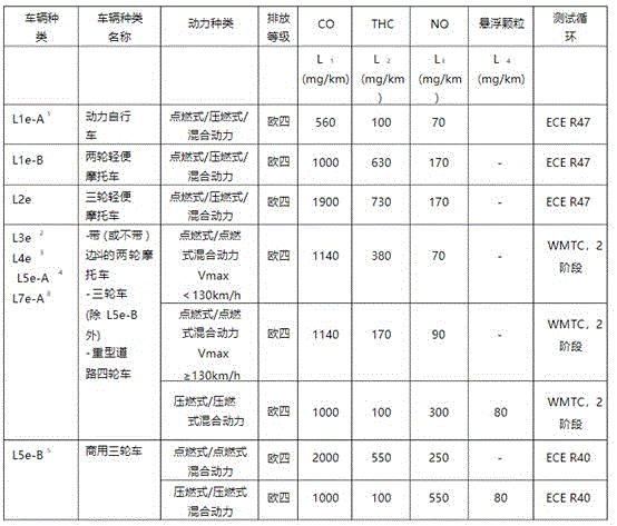
With the improvement of the environmental protection requirement, the requirement of each country on the emission standard is higher and higher, so the emission limit value of the motorcycle must be further reduced, and the environmental protection performance index of the motorcycle is improved.
Disclosure of Invention
The invention aims to provide a low-emission fuel motorcycle capable of reducing an emission limit value.
A low-emission fuel motorcycle comprises
A frame;
a front wheel;
a rear wheel;
a vehicle suspension system associated with the front and rear wheels for providing shock absorption to the front and rear wheels;
a controller;
the engine is supported on the frame, at least one of the front wheels or the rear wheels is in transmission coupling with the engine, a combustion chamber is arranged in the engine, the engine comprises a cylinder body and a cylinder cover connected with the cylinder body, and an exhaust passage is arranged on the cylinder cover;
the exhaust system is used for discharging exhaust gas in the engine and comprises an exhaust pipeline and a gas treatment assembly communicated with the exhaust pipeline, and the exhaust pipeline is communicated with the exhaust passage;
the cylinder cover is provided with an air supplementing channel for mixing air into waste gas discharged from the combustion chamber, and the air supplementing channel is communicated with the exhaust channel;
the air supply system comprises an air supply pipe for inputting air into the air supply channel, an air supply filter, an engine air filter and a main air inlet pipe, wherein the main air inlet pipe is communicated with the engine air filter, and the air supply pipe is communicated with the air supply filter.
Optionally, a vertical plane is made along the central line of the motorcycle, and the included angle between the projection of the axial line of the air supply channel in the length direction on the vertical plane and the projection of the axial line of the exhaust channel in the length direction on the vertical plane is smaller than 90 degrees.
Optionally, a vertical plane is made along the center line of the motorcycle, an included angle between the projection of the axis in the length direction of the air replenishing channel on the vertical plane and the projection of the axis in the length direction of the exhaust channel on the vertical plane is greater than or equal to 90 degrees, an air flow buffer area is arranged on the cylinder cover and is communicated with the air replenishing channel and the exhaust channel, the area of the cross section of the air flow buffer area is greater than that of the cross section of the air replenishing channel, and the air flow buffer area is in one of a horn shape, a hemisphere shape and a cylinder shape.
Optionally, an air supply channel seat is arranged on the cylinder cover, and the air supply channel is arranged on the air supply channel seat; the air supply channel seat is a part of the cylinder cover; the air supply channel seat is provided with a connecting plane, and the axis of the air supply channel is perpendicular to any two crossed straight lines in the connecting plane.
Optionally, the cylinder cover is further provided with a cooling water channel, a cavity for mounting the valve spring, a lubricating oil cavity and an air inlet channel, and the air supply channel is mutually independent of the cooling water channel, the cavity for mounting the valve spring, the lubricating oil cavity and the air inlet channel; the cooling water channel is adjacent to the air supply channel, a blocking part is arranged between the cooling water channel and the air supply channel, and the air supply channel is partially formed on the blocking part; the blocking portion is a part of the cylinder head.
Optionally, the air intake system further comprises a switch valve communicated with the air make-up air filter, and when the engine is started by a cold machine, the switch valve is opened; when the engine reaches a preset temperature, the switch valve is closed; the switch valve is one of a flow control valve, a duty ratio electromagnetic valve, a normally open electromagnetic valve and a normally closed electromagnetic valve; the switch valve is controlled by the controller or valve controller of the motorcycle.
Optionally, the air supply air filter comprises an air filter shell and filter paper arranged in the air filter shell, an air inlet interface is arranged at one end of the air filter shell, and an air outlet interface is arranged at the other end of the air filter shell.
Optionally, the air intake system still includes the check valve, and this check valve is provided with the link of admitting air and the link of giving vent to anger, and the link of admitting air communicates with the empty filter of tonifying qi, and the link of giving vent to anger communicates with the moisturizing pipe.
Optionally, the air intake system further comprises an air pump for pumping air into the air make-up air filter, and the air pump is communicated with the air make-up air filter through a pipeline; the air pump is controlled by a controller of the motorcycle or an air pump controller.
Optionally, the engine is a multi-cylinder engine comprising a front cylinder and a rear cylinder, the switch valve is communicated with a first air supply branch pipe, the first air supply branch pipe corresponds to the front cylinder of the engine, and the first air supply branch pipe is close to the front cylinder of the engine; the first air supply branch pipe comprises a first straight pipe part connected with the switch valve, a second straight pipe part and a bent pipe part connecting the first straight pipe part and the second straight pipe part, and the length direction of the first air supply branch pipe part is the same as the height direction of the motorcycle; the length direction of the second air supply branch pipe is the same as the width direction of the motorcycle; the second air supply branch pipe comprises a first pipe body connected with the switch valve, a pipe joint connected with the first pipe body and a second pipe body wound from one side of the engine to the other side of the engine, the second pipe body is connected with the pipe joint, and the pipe joint is fixed on a rear cylinder of the engine through a bolt; the first pipe body comprises a first bent pipe part, an arc-shaped pipe part connected with the first bent pipe part and a second bent pipe part connected with the arc-shaped part, and the second bent pipe part is connected with the pipe joint; the second body includes first curved pipe portion, second curved pipe portion and third curved pipe portion, and third curved pipe portion and check valve intercommunication.
Optionally, the engine is a single-cylinder engine, the switch valve is connected with a gas pipe, the gas pipe comprises a straight pipe-shaped first pipe part, a straight pipe-shaped second pipe part and an elbow pipe part connecting the first pipe part and the second pipe part, and the second pipe part is communicated with the one-way valve.
The invention has the advantages that:
1. the waste gas after combustion in the combustion chamber is secondarily oxidized, the content of CO and NOx in the waste gas is reduced, the tail gas emission limit value is reduced to be below 700mg/km of CO, below 47.6mg/km of NMHC and below 70mg/km of THC, and the environmental protection index of the motorcycle is improved.
2. The waste gas is subjected to secondary oxidation, CO and NOx in the waste gas are oxidized to release heat, the heat inside the engine at the starting stage of the cold machine is increased, the engine quickly reaches the preset working temperature, the starting time of the cold machine is shortened, the waste gas is further reduced, and the environmental protection performance of the motorcycle is improved. Meanwhile, the cold machine starting time is shortened, the temperature rising time of lubricating oil in the engine is short, the internal abrasion of the engine is reduced, and the service life of the engine is prolonged.
3. The secondary oxidation of the waste gas shortens the starting time of the cold machine and improves the controllability of the motorcycle.
Drawings
FIG. 1 is a perspective view of a motorcycle according to the present invention.
FIG. 2 is a perspective view of the engine and exhaust system of FIG. 1
Fig. 3 is a perspective view of the engine of fig. 1.
Fig. 4 is a perspective view from another perspective of the engine of fig. 1.
Fig. 5 is a perspective view of the cylinder head and the air supplement pipe of fig. 4.
Fig. 6 is a perspective view of the cylinder head of fig. 5.
FIG. 7 is a perspective view of the cylinder head of FIG. 5 from another perspective.
Fig. 8 is a cross-sectional view of the cylinder head of fig. 6 with the angle of inclination α of the charge air passage greater than 90 °.
Fig. 9 is a cross-section of the cylinder head of fig. 6 with the angle of inclination α of the charge air passage equal to 90 °.
Fig. 10 is a cross-sectional view of the cylinder head of fig. 6 with the angle of inclination α of the charge air passage less than 90 °.
Fig. 11 is a cross-sectional view of the air supply pipe and the exhaust passage in fig. 1, wherein an included angle β between the air supply pipe and the axis of the exhaust passage is smaller than 90 °.
Fig. 12 is a cross-sectional view of the air supply pipe and the exhaust passage in fig. 1, wherein an included angle beta between the air supply pipe and the axis of the exhaust passage is greater than 90 degrees.
Fig. 13 is a perspective view of the make-up air filter and the engine air filter of fig. 2, taken independently of each other.
Fig. 14 is a cross-sectional view of the air make-up filter of fig. 2.
Fig. 15 is a cross-sectional view of the first branch pipe of fig. 13 with a choke plug disposed therein.
Figure 16 is a cross-sectional view of the difference in pipe diameter between the first branch pipe and the second branch pipe of figure 13.
FIG. 17 is a cross-sectional view of the first branch pipe and the second branch pipe in FIG. 13 with different pipe diameters and a choke plug in the first branch pipe.
Fig. 18 is a perspective view of the air make-up filter and the engine air filter of fig. 2, which are independent from each other, and the air make-up filter corresponds to a single cylinder engine.
FIG. 19 is a perspective view of the air pump of the make-up air filter of FIG. 2 actively supplying air and corresponding to a two-cylinder engine.
FIG. 20 is a perspective view of the air make-up air filter of FIG. 2 with the air pump actively supplying air and corresponding to a single cylinder engine.
Fig. 21 is an exploded view of the common engine air filter of fig. 2 and corresponding to a two-cylinder engine.
Fig. 22 is a cross-sectional view of the first branch pipe of fig. 21 with a choke plug disposed therein.
Figure 23 is a cross-sectional view of the difference in pipe diameter between the first branch pipe and the second branch pipe of figure 21.
FIG. 24 is a cross-sectional view of the first branch pipe and the second branch pipe in FIG. 21 with different pipe diameters and a choke plug in the first branch pipe.
FIG. 25 is an exploded view of the common engine air filter of FIG. 2 and corresponding single cylinder engine
Fig. 26 is an exploded view of the common engine air filter active feed of fig. 2 and corresponding to a two cylinder engine.
FIG. 27 is an exploded view of the common engine air filter plenum of FIG. 2 and corresponding single cylinder engine.
Fig. 28 is a perspective view of the exhaust system of fig. 2.
Fig. 29 is an exploded view of the exhaust system of fig. 2.
Fig. 30 is a cross-sectional view of the graphite sleeve of fig. 29.
FIG. 31 is a cross-sectional view of the gas treatment assembly of FIG. 28.
FIG. 32 is a perspective view of the spark collector of FIG. 31.
Detailed Description
In order to make the technical solutions of the present application better understood, the technical solutions of the embodiments of the present application will be clearly and completely described below with reference to the drawings of the embodiments of the present application, and the structures related to the present application or technical terms used in the structures will be further described below, which are understood and explained according to the general genus in the art without specific indications.
The terms "first", "second", and the like in the present disclosure are merely for convenience of description to distinguish different constituent elements having the same name, and do not denote a sequential or primary-secondary relationship. In the following description, the front-rear direction and the left-right direction correspond to directions based on the viewing angle of the rider, and the description of the front, rear, left, right, up, down directions is made as the directions shown in fig. 1, and in the following description, the front-rear direction and the left-right direction correspond to directions based on the viewing angle of the rider.
Duty cycle
The proportion of the time that a signal or system is in the on state over the entire period is called the duty cycle or power period. The duty cycle is typically expressed in percentage or ratio. A cycle is the time it takes for a signal to complete one switching cycle. The duty cycle (percent system) can be formulated as D = PW/T x 100% [2 ]; similarly, the duty cycle (decimal) can also be expressed as: d = PW/T. Where D denotes the duty cycle, PW denotes the pulse width (pulse effective time), and T denotes the total period of the signal. Thus, a duty cycle of 60% means that the signal is on for 60% of the time, but off for 40% of the time. The "on time" for a 60% duty cycle may be a fraction of a second, a day, or even a week, depending on the cycle length. The duty cycle may be used to describe the percentage of the turn-on signal in the electrical device, such as the turn-on time of a high frequency power switching device in a switching power supply or the time during which a living system (e.g., a neuron) remains active. The duty cycle of a periodic signal is conceptually the same as the duty cycle, but is typically expressed not in percent but in a fraction of no more than 1. The duty cycle may also be represented by the greek letter α.
As shown in fig. 1, the motorcycle includes a frame 10, an engine 20, a front wheel 41, a rear wheel 42, a fuel system 70, a body cover 80, an instrument panel 90, a steering system 11, a suspension system 13, a controller 14, and the like. The motorcycle is an all-terrain vehicle, which utilizes a fuel-powered engine 20 to drive rear wheels 42. Suspension system 13 includes a front suspension 131 and a rear suspension 132, front suspension 131 being coupled to a front portion of frame 10, front suspension 131 being associated with front wheel 41. A rear suspension 132 is engaged at the rear of frame 10, rear suspension 132 being associated with the rear wheels. A fuel system 70 is disposed on frame 10, and fuel system 70 is configured to provide fuel to engine 20.
As shown in fig. 2-4, engine 20 is located at a lower middle portion of frame 10, and engine 20 is provided with a combustion chamber (not shown) into which fuel from fuel system 70 flows through a pipe, and then a spark plug ignites the fuel, which explodes to generate power that pushes a piston (not shown) downward, thereby powering the motorcycle. The engine 20 includes a cylinder block 21, a cylinder head 22, a cylinder head cover 23, a crankcase 24, a transmission case 25, and the like. The crankcase 24 includes an upper crankcase 241 and a lower crankcase 242, and the cylinder block 21 and the upper crankcase 241 are usually cast integrally, i.e., the cylinder block 21 is a part of the upper crankcase 241. The lower crankcase 242 serves for storing lubricating oil and closes the upper crankcase 241, wherein the lower crankcase 242 is also referred to as an oil pan. The cylinder head 22 is attached to the cylinder block 21, and seals the cylinder block 21 from above. The head cover 23 is connected to the cylinder head 22 and seals an upper portion of the cylinder head 22 to form a closed cavity.
As shown in fig. 5 to 8, in some embodiments, the cylinder head 22 is provided with a cooling water passage 221, a valve-mounting hole 222, a valve-spring-mounting cavity 223, a lubrication cavity 224, a combustion chamber-constituting cavity 225, an intake passage 226 communicating with the combustion chamber-constituting cavity 225, an exhaust passage 227 communicating with the combustion chamber-constituting cavity 225, and the like, wherein exhaust gas generated in the combustion chamber is exhausted from the exhaust passage 227. A gas replenishment passage 229a is provided in the cylinder head 22, and the gas replenishment passage 229a communicates with the exhaust passage 227. Air flows from the air supply passage 229a into the exhaust passage 227, and the exhaust gas in the exhaust passage is secondarily oxidized. The exhaust emission limit is reduced by secondary oxidation of the exhaust gas discharged from combustion to a CO of 700mg/km or less, an NMHC of 47.6mg/km or less, and a THC of 70mg/km or less. The air supply channel 229a is provided with an air inlet and an air outlet, and the vector angle between the flow direction of the air flowing into the exhaust channel from the air outlet of the air supply channel and the flow direction of the waste gas flowing through the exhaust channel is greater than 90 degrees. The embodiment can be used as an independent scheme, and can also be combined with the prior art to form a new technology.
As shown in FIG. 8, in some embodiments, an air flow relief area 2293a is provided on the cylinder head 22, the air flow relief area 2293a being in communication with the makeup air passage 229 a. Air passes sequentially through make-up air passage 229a, through air flow buffer region 2293a and into exhaust passage 227. The cross-sectional area of the gas flow relief area 2293a is larger than the cross-sectional area of the gas replenishment channel 229 a. And airflow buffer area 2293a is one of a trumpet, a hemisphere, and a cylinder. The air flow buffer area 2293a slows the rate of air flow out of the air replenishment passageway 229a and after the air impacts the inner wall of the air flow buffer area 2293a, the flow direction of the air changes so that the flow direction of the air substantially coincides with the flow direction of the exhaust gas. The embodiment can be used as an independent scheme, and can also be combined with the prior art to form a new technology.
Specifically, the air replenishing passage 229a is independent from the cooling water passage 221 provided in the cylinder head 22, the intake valve spring mounting cavity 223, the camshaft lubricating cavity 224, the combustion chamber constituting cavity 225, and the intake passage 226. The cooling water passage 221 is adjacent to the air supplement channel 229a, and a blocking portion 2294 is provided between the cooling water passage 221 and the air supplement channel 229 a. The blocking portion 2294 is a part of the cylinder head 22. The gas supplement passage 229a is partially formed on the blocking portion 2294, so that the blocking portion 2294 provides a space for forming the gas supplement passage 229 a.
As shown in FIGS. 5-8, in some embodiments, a charge air passage seat 228 is provided on the cylinder head 22, with the charge air passage seat 228 being a part of the cylinder head 22. The replenishment passage 229a is provided on the replenishment passage seat 228. And the top surface 2281 of the air supplement channel seat 228 is a plane, and the axis of the air supplement channel 229a is vertical to the top surface 2281. The engine 20 also includes an air intake system 30 which may be part of the engine or a system on the motorcycle separate from the engine, as desired. The intake system 30 includes an air supply pipe 301a, and air is supplied to the air supply passage 229a after passing through the air supply pipe 301 a. The air supply pipe 301a is connected with a connecting seat 3011, and the connecting seat 3011 is fixed on the air supply passage seat 228 through a screw, so that the air supply pipe 301a is fixed. And a sealing gasket 3012 is arranged between the connecting seat 3011 and the air supply channel seat 228. Seal gasket 3012 realizes tonifying qi passageway 228 and intake pipe 301a sealing connection, ensures cylinder head leakproofness. The embodiment can be used as an independent scheme, and can also be combined with the prior art to form a new technology.
As shown in fig. 9, in some embodiments, the embodiment is different from the above-described embodiments in that a supplement passage 229b is provided on the cylinder head 22, an intake port and an exhaust port are provided on the supplement passage 229b, and the supplement passage 229b communicates with the exhaust port 227. The included angle between the projection of the axial line of the length direction of the air supplementing channel on the vertical plane and the projection of the axial line of the length direction of the exhaust channel on the vertical plane is greater than or equal to 90 degrees, namely the vector included angle between the flow direction of the air flowing into the exhaust channel from the air outlet of the air supplementing channel and the flow direction of the waste gas flowing through the exhaust channel is greater than or equal to 90 degrees. An air flow relief area 2293b is provided in cylinder head 22, and air flow relief area 2293b is in communication with makeup passage 229 b. The cross-sectional area of the gas flow relief area 2293b is greater than the cross-sectional area of the gas replenishment channel 229 b. And airflow buffer area 2293b is one of a trumpet, a hemisphere and a cylinder. The air flow buffer area 2293b slows the rate of air flow out of the air replenishment passageway 229b and, after the air impinges on the air flow buffer area 2293b, the direction of flow of the air flow changes to substantially the same direction as the flow of the exhaust gas. The embodiment can be used as an independent scheme, and can also be combined with the prior art to form a new technology.
As shown in fig. 10, in some embodiments, the embodiment is different from the above embodiments in that an air supplement passage 229c is provided on the cylinder head, an air inlet and an air outlet are provided on the air supplement passage 229c, and the air supplement passage 229c communicates with the air discharge passage 227. The vertical plane is made along the central line of the motorcycle, the included angle between the projection of the axial line of the length direction of the air supplementing channel on the vertical plane and the projection of the axial line of the length direction of the exhaust channel on the vertical plane is smaller than 90 degrees, namely the vector included angle between the flow direction of the air flowing into the exhaust channel from the air outlet of the air supplementing channel and the flow direction of the waste gas flowing through the exhaust channel is smaller than 90 degrees. An included angle smaller than 90 degrees can ensure that when air enters the exhaust passage 227, the air and the waste gas move in the same direction, the waste gas has no resistance, the exhaust efficiency is high, and the waste gas oxidation effect is good. In particular, in a more preferred embodiment, the angle between the projection of the axis of the length of the air supply duct on the vertical plane and the projection of the axis of the length of the exhaust duct on the vertical plane is 10-30 ° when the plane is taken along the centre line of the motorcycle. The embodiment can be used as an independent scheme, and can also be combined with the prior art to form a new technology.
As shown in fig. 11 and 28-29, in some embodiments, engine 20 also includes an exhaust system 60. Of course, the exhaust system may be part of the engine or may be a system on the motorcycle separate from the engine. This embodiment differs from the previous embodiments in that the present embodiment is supplemented with air into the exhaust system 60 to secondarily oxidize the exhaust gas in the exhaust passage 227. Specifically, the exhaust system 60 includes an exhaust conduit 61a and a gas treatment assembly 62, the gas treatment assembly 62 being in communication with the exhaust conduit 61 a. The inlet port of the exhaust duct 61a corresponds to the outlet port of the exhaust passage 227, and the exhaust passage 227 communicates with the exhaust duct 61 a. The exhaust duct 61a is provided with an air make-up connection pipe 6012 a. Exhaust gas from the engine combustion chamber is thus directed through exhaust port 227 into exhaust conduit 61a and then into gas treatment assembly 62.
Further, the intake system 30 includes an air supplement pipe 301a, and the air supplement pipe 301a communicates with the exhaust duct 61 a. Fresh air is injected into the exhaust duct 61a via the air supplement pipe 301a, and an air flow in which an exhaust-air interval is arranged is formed in the exhaust duct 61 a. Secondary oxidation of exhaust gas discharged from combustion into the exhaust pipe 61a reduces the exhaust emission limit to 700mg/km or less for CO, 47.6mg/km or less for NMHC, and 70mg/km or less for THC. The air supplement pipe 301a is close to the air inlet of the air discharge duct 61 a. The gas supply pipe 301a is connected to a gas supply connection pipe 6012 a. Wherein, the vertical plane is made along the central line of the motorcycle, and the included angle between the projection of the axial line of the length direction of the air supplement pipe on the vertical plane and the projection of the axial line of the length direction of the exhaust pipeline on the vertical plane is less than 90 degrees. That is, the vector angle between the flow direction of the air flowing from the air supply pipe 301a into the exhaust pipe and the flow direction of the exhaust gas flowing into the exhaust pipe is smaller than 90 °. Of course, in a more preferred embodiment, the angle between the projection of the axis of the length of the filler pipe on the vertical plane and the projection of the axis of the length of the exhaust pipe on the vertical plane is between 10 ° and 30 ° taken along the centre line of the motorcycle. Namely, the vector included angle between the flow direction of the air flowing into the exhaust pipeline from the air supplementing pipe and the flow direction of the waste gas flowing into the exhaust pipeline is 10-30 degrees. The present embodiment may be implemented as an independent solution, or may be arbitrarily combined with the above embodiments or the prior art to form a new technology.
In some embodiments, as shown in fig. 12, the present embodiment differs from the above embodiments in that the angle between the projection of the axis of the length direction of the inflation tube on the vertical plane and the projection of the axis of the length direction of the exhaust duct on the vertical plane is greater than 90 °. That is, the vector angle between the flow direction of the air flowing into the exhaust duct 61b from the air supplement pipe 301b and the flow direction of the exhaust gas flowing into the exhaust duct 61b is greater than 90 °, and an air flow buffer zone 6013 communicating with the air supplement pipe 301b is provided on the exhaust duct 61 b. An air supply connecting pipe 6012b is disposed on the exhaust duct 61b, an air supply pipe 301b is connected to the air supply connecting pipe 6012b, and an air flow buffer zone 6013 is disposed on the air supply connecting pipe 6012 b. The cross-sectional area of the gas flow buffer zone 6013 is larger than the cross-sectional area of the insufflation tube 301 b. The gas flow buffer zone 6013 is one of a trumpet, a hemisphere, and a straight cylinder. The air flow buffer zone 6013b slows the rate of air flowing out of the aeration tube 301b, and after the air hits the air flow buffer zone 6013, the flow direction of the air flow is reversed such that the flow direction of the air flow substantially coincides with the flow direction of the exhaust gas. In other embodiments, the angle between the projection of the axis of the length of the filler pipe on the vertical plane and the projection of the axis of the length of the exhaust duct on the vertical plane is equal to 90 ° when the motorcycle is viewed in a vertical plane along the centre line of the motorcycle. The present embodiment may be implemented as an independent solution, or may be arbitrarily combined with the above embodiments or the prior art to form a new technology.
As shown in fig. 13, in some embodiments, the air intake system 30 supplies filtered air to the air make-up passage 229a, and the air intake system 30 includes an air intake passage 31, an air make-up air filter 34, and an engine air filter 33 and a main intake pipe 333 that supply air to the engine 20. The engine air filter 33 and the air supply air filter 34 are independent from each other, that is, the air supply pipe 301a is communicated with the air supply air filter 34, and the main air inlet pipe 333 is communicated with the engine air filter 33. The engine air filter 33 and the make-up air filter 34 share the same intake passage 31. When the engine is started, the scheme of supplementing air to the waste gas to realize secondary oxidation of the waste gas is combined with the embodiment, and filtered air is input into the air supplementing pipe.
Specifically, the side wall of the intake passage 31 is provided with an intake port 311, and the intake port 311 faces the direction of the rear wheels of the vehicle, so that the stability of the intake air amount can be ensured. The proximity of the air inlet 311 to the instrument panel 90 increases the height of the air inlet 311, keeping the air entering through the air inlet 311 clean. The intake passage 31 includes a first pipe 313, a second pipe 314, and a third pipe 315 connected to the second pipe 314. Wherein the air inlet 311 is provided on a side wall of the first duct 313, and a length direction of the first duct 313 substantially coincides with a height direction of the motorcycle. And the second conduit 314 is a hose of L-shaped configuration. One end of the second pipe 314 is sleeved on one end of the first pipe 313, a locking ring 316 is sleeved on the overlapping part of the second pipe 314 and the first pipe 313, and the locking ring 316 locks the connecting part of the first pipe 313 and the second pipe 314 to keep the tightness of the connected first and second pipes. The third pipe 315 has a length direction substantially identical to that of the motorcycle, and one end of the third pipe 315 is connected to the engine air cleaner 33 and the other end is connected to the second pipe 314. The present embodiment may be implemented as an independent solution, or may be arbitrarily combined with the above embodiments or the prior art to form a new technology.
As shown in fig. 13-14, in some embodiments, the air make-up filter 34 has a tubular structure, and the air make-up filter 34 is covered by a rubber sleeve 340, and the rubber sleeve 340 is connected to one side of the frame 10, so as to fix the air make-up filter 34. The supplementary air filter 34 includes an air filter case 341 and a filter paper 342 provided in the air filter case 341, the filter paper 342 is filled in the bottom of the air filter case 341, and the filter paper 342 does not fill the entire air filter case 341. The filter paper 342 is filled in the air filter housing 341, the air is straight in and out in the air make-up air filter 34, and the air make-up air filter 34 has high air filtering efficiency. An air inlet connector 3411 is arranged at one end of the air filtering shell 341, and the air supply branch pipe 318 is sleeved on the air inlet connector 3411. The other end of the air filter housing 341 is provided with an air outlet port 3412.
Specifically, a pipe joint 317 is disposed on a side wall of the intake passage 31, and a linear distance from the pipe joint 317 to the instrument panel 90 is greater than a linear distance from the intake 311 to the instrument panel 90. The pipeline joint 317 is connected with a gas supplementing branch pipe 318, and the gas supplementing branch pipe 318 is connected with the gas supplementing air filter 34. After entering the air inlet channel 31 through the air inlet 311, a part of the fresh air enters the air supply branch pipe 318 through the pipe joint 317, and then enters the air supply filter 34. The present embodiment may be implemented as an independent solution, or may be arbitrarily combined with the above embodiments or the prior art to form a new technology.
As shown in fig. 13-14, in some embodiments, the air intake system 30 further includes an on-off valve 322a and a one-way valve 323a in communication with the outlet end of the make-up air filter 34, the on-off valve 322a being in communication with the make-up air filter 34 via a conduit. The switch valve 322a is a duty cycle solenoid valve, or one of a normally open solenoid valve or a normally closed solenoid valve. The on-off valve 322a is controlled by the controller 14 of the motorcycle. The controller is a vehicle-mounted computer. Or in other embodiments, the motorcycle further includes a valve controller, which is an electronic control unit separate from the controller 14. The on-off valve 322a is controlled by a valve controller. When the engine is cold started, the on-off valve 322a is opened, and the air filtered by the make-up air filter 34 passes through the on-off valve 322a and enters the make-up air pipe 301 a. When the engine is started by the cold machine, the air supplement at the cold machine stage is realized by combining the scheme of realizing the secondary oxidation of the waste gas through air supplement. When the engine reaches a preset temperature, the on-off valve 322a is closed, thereby stopping the supply of air to the air supplement pipe 301 a. The present embodiment may be implemented as an independent solution, or may be arbitrarily combined with the above embodiments or the prior art to form a new technology.
As shown in FIG. 13, in some embodiments, the engine is a multi-cylinder engine including front and rear cylinders. Two air outlet ends are provided on the on-off valve 322a, one air outlet end of the on-off valve 322a is connected with a first air supply branch pipe 329, and the air outlet end of the first air supply branch pipe 329 is connected with a front cylinder close to the engine. The other outlet end of the on-off valve 322a is connected to a second air supply branch pipe 328, and the outlet end of the second air supply branch pipe 328 is close to the rear cylinder of the engine. The first air supply branch 329 includes a first straight tube portion 3291, a second straight tube portion 3292, and a bent tube portion 3293 connecting the first straight tube portion 3291 and the second straight tube portion 3292. Of course, the specific shape of first delivery manifold 329 may be redesigned depending on the arrangement of first delivery manifold 328 on engine 20 and frame 10.
Specifically, the second air supply branch pipe 328 includes a first pipe 3281 connected to the on-off valve 322a, a pipe connector 3282 connected to the first pipe 3281, and a second pipe 3283 wound from one side of the engine 20 to the other side of the engine 20, the second pipe 3283 is connected to the pipe connector 3282, and the pipe connector 3282 is connected to the rear cylinder of the engine 20 by a bolt. The first tube body 3281 includes a first bent tube portion 3281a, an arc tube portion 3281b connected to the first bent tube portion 3281a, and a second bent tube portion 3281c connected to the arc portion 3281b, and the second bent tube portion 3281c is connected to a tube connector 3821 b; the second tubular body 3283 includes a first bent pipe portion 3283a, a second bent pipe portion 3283b and a third bent pipe portion 3283c, and the third bent pipe portion 3283c is connected to the check valve 323 a. Of course, the specific shape of first tube 3281 may be rearranged based on the arrangement of first tube 3281 on engine 20 and frame 10. The present embodiment may be implemented as an independent solution, or may be arbitrarily combined with the above embodiments or the prior art to form a new technology.
As shown in FIG. 15, in some embodiments, a choke plug 320a is provided in the first plenum 329. The distribution of the air flow after passing the on-off valve 322a can be directly controlled by the throttle plug 320 a. Of course, in other embodiments, throttle plug 320a may be disposed in second delivery branch 328, or throttle plug 320a may be disposed in both first and second conduits.
As shown in fig. 16, in some embodiments, there is a difference between the pipe diameter of first air supply branch 329 and the pipe diameter of second air supply branch 328, the difference being that the pipe diameter of first air supply branch 329 is larger than the pipe diameter of second air supply branch 328, or that the pipe diameter of first air supply branch 329 is smaller than the pipe diameter of second air supply branch 328.
As shown in fig. 17, in some embodiments, a choke plug 320a is provided in the first air supply branch 329, and the first air supply branch 329 and the second air supply branch 328 have different pipe diameters, and a choke plug 320a is provided in the first air supply branch 329. The distribution of the air flow after passing the on-off valve 332a can be directly controlled by the throttle plug 320 a. Of course, in other embodiments, the throttle plug 320a may be disposed in the second conduit 328, or both the first and second conduits may have the throttle plug 320a disposed thereon.
In some embodiments, as shown in fig. 18, the engine is a single cylinder engine, the switch valve 322b has an outlet end, an air pipe 326 is connected to the outlet end of the switch valve 322b, the outlet end of the air pipe 326 is connected to a one-way valve 323b, and the one-way valve 323b is connected to the air supplement pipe 301a close to the engine cylinder. The gas pipe 326 includes a first pipe portion 3261 and a second pipe portion 3262 having a straight pipe shape, and an elbow pipe portion 3263 connecting the first pipe portion 3261 and the second pipe portion 3262, and the second pipe portion 3262 is connected to the check valve 323 b. Of course, the specific shape of the air delivery conduit 326 may be redesigned depending on the arrangement of the air delivery conduit on the engine and the frame. The present embodiment may be implemented as an independent solution, or may be arbitrarily combined with the above embodiments or the prior art to form a new technology.
As shown in fig. 13 and 18, in some embodiments, the air make-up filter 34 is a natural air suction type air make-up filter, and the air make-up filter 34 is in communication with the air make-up pipe 301 a. The engine replenishes air into the exhaust passage or the exhaust pipeline in a natural air suction mode.
As shown in fig. 19 and 20, in some embodiments, the engine is a multi-cylinder engine or a single-cylinder engine, and the air intake system 30 further includes an air pump 35 for pumping air into the make-up air filter 34, and the air pump 35 is in communication with the make-up air filter 34 through a pipe. The air pump 35 is controlled by the controller 14; the controller 14 controls the air pump 35 to be turned on, thereby controlling the amount of air supplied from the air pump 35 to the air replenishing passage 229 a. Of course in other embodiments the motorcycle further comprises an air pump controller under which the air pump 35 is controlled.
As shown in fig. 21, in some embodiments, the air intake system 30 provides filtered air to the exhaust. The air intake system 30 includes an engine air filter 33, an on-off valve 322c, a check valve 323c, and a main intake pipe 333, wherein the engine air filter 33 includes an air filter box 331 and an air filter 332. The main intake pipe 333 communicates the engine air cleaner 33 and the combustion chamber. An intake branch pipe 3331 is connected to the main intake pipe 333, the intake branch pipe 3331 is connected to the on-off valve 322c via a pipe, and the on-off valve 322c is communicated with the inflation pipe 301 a. Fresh air passes through the intake branch pipe 3331 and the on-off valve 322c, and enters the air supplement pipe 301 a. When the engine is started, the filtered air is input into the air supply pipe by combining the scheme of realizing the secondary oxidation of the waste gas through air supply.
The switch valve 322c is a duty cycle solenoid valve, or one of a normally open solenoid valve and a normally closed solenoid valve, and the switch valve 322c is controlled by the controller 14. Alternatively, the motorcycle further includes a valve controller to which the on-off valve 322c is controlled. The switch valve 322c works when the engine is started cold, and filtered air enters the air supplementing channel through the switch valve 322 c. The present embodiment may be implemented as an independent solution, or may be arbitrarily combined with the above embodiments or the prior art to form a new technology.
As shown in FIG. 21, in some embodiments, the engine is a multi-cylinder engine including front and rear cylinders. Two air outlet ends are provided at the open/close valve 322c, one air outlet end of the open/close valve 322c is connected to a first air supply branch pipe 329c, and the air outlet end of the first air supply branch pipe 329c is connected to a front cylinder adjacent to the engine. The other gas outlet end of the on-off valve 322c is connected with a second gas supply branch pipe 328c, and the gas outlet end of the second gas supply branch pipe 328c is close to the rear cylinder of the engine; the first air supply branch tube 329c includes a first straight tube portion 3291c, a second straight tube portion 3292c, and a bent tube portion 3293c connecting the first straight tube portion 3291c and the second straight tube portion 3292 c. Of course, the specific shape of the first air supply branch 329c may be redesigned depending on the arrangement of the first air supply branch 329c on the engine 20 and the frame 10. The second air-feeding branch pipe 328c includes a first pipe 3281c connected to the switching valve 322c, a pipe connector 3282c connected to the first pipe 3281c, and a second pipe 3283c wound from one side of the engine 20 to the other side of the engine 20, the second pipe 3283c is connected to the pipe connector 3282c, and the pipe connector 3282c is connected to the rear cylinder of the engine 20 by a bolt. Of course, the specific shape of the first tube 3281c can be rearranged according to the arrangement of the first tube 3281c on the engine 20 and the frame 10. The present embodiment may be implemented as an independent solution, or may be arbitrarily combined with the above embodiments or the prior art to form a new technology.
As shown in fig. 22, in some embodiments, a choke plug 320c is provided in the first air supply branch 329c, and the distribution of the air flow passing through the on-off valve 322c may be directly controlled by the choke plug 320 c. Of course, in other embodiments, throttle plug 320c may be disposed in second delivery branch 328c, or throttle plug 320c may be disposed in both first and second conduits.
As shown in FIG. 23, in some embodiments, there is a difference between the pipe diameter of first air supply branch 329c and the pipe diameter of second air supply branch 328c, the difference being that the pipe diameter of first air supply branch 329c is greater than the pipe diameter of second air supply branch 328c, or that the pipe diameter of first air supply branch 329c is smaller than the pipe diameter of second air supply branch 328c
As shown in fig. 24, in some embodiments, a choke plug 320c is provided in the first air supply branch 329c, and the first air supply branch 329c and the second air supply branch 328 have different pipe diameters, and a choke plug 320c is provided in the first air supply branch 329 c. The distribution of the air flow after passing through the on-off valve can be directly controlled by the choke plug 320 c. Of course, in other embodiments, the throttle plug 320c may be disposed in the second pipe, or both the first pipe and the second pipe may be disposed with the throttle plug 320 c.
In some embodiments, as shown in fig. 25, the engine is a single cylinder engine, the on-off valve 322c has an outlet end, an air pipe 326c is connected to the outlet end of the on-off valve 322c, the outlet end of the air pipe 326c is connected to a one-way valve 323c, and the one-way valve 323c is connected to the air supplement pipe 301a near the engine cylinder. The gas pipe 326c includes a first pipe portion 3261c having a straight pipe shape, a second pipe portion 3262c having a straight pipe shape, and an elbow pipe portion 3263c connecting the first pipe portion 3261c and the second pipe portion 3262c, and the second pipe portion 3262c is connected to the check valve 323 bc. Of course, the specific shape of the air delivery conduit 326c can be re-designed according to the arrangement of the air delivery conduit on the engine and the frame. The present embodiment may be implemented as an independent solution, or may be arbitrarily combined with the above embodiments or the prior art to form a new technology.
As shown in fig. 8 and 26-27, in some embodiments, the inlet manifold 3331 is a pumped gas supplement via an air pump 35 c. The air pump 35c is controlled by the controller 14; the controller 14 controls the air pump to be turned on, thereby controlling the amount of air supplied from the air pump 35c to the air replenishing passage 229 a. The motorcycle may further include an air pump controller to which the air pump 35c is controlled. The motorcycle is specially provided with a valve controller to control the air pump 35c to be opened and closed, thereby facilitating the wiring of the motorcycle. The present embodiment may be implemented as an independent solution, or may be arbitrarily combined with the above embodiments or the prior art to form a new technology.
28-29, in some embodiments, exhaust system 60 is for a two-cylinder engine, exhaust system 60 including exhaust conduit 61 and gas treatment assembly 62, and exhaust passes through exhaust conduit 61 to gas treatment assembly 62 and then to the environment. The exhaust pipe 61 is installed along one side of the frame 10, and the exhaust pipe 61 includes a front cylinder exhaust pipe 611 and a rear cylinder exhaust pipe 612, wherein the front cylinder exhaust pipe 611 includes a front bent pipe section 6111 and a front straight pipe section 6112, the rear cylinder exhaust pipe 612 includes a rear bent pipe section 6121 and a rear straight pipe section 6122, and the front straight pipe section 6112 of the front cylinder exhaust pipe 611 communicates with the rear straight pipe section 6122 of the rear cylinder exhaust pipe 612. The exhaust pipe 61 is provided with two front stage catalysts and one rear stage catalyst 617. And a catalyst is added to carry out more than one catalytic oxidation reaction on the tail gas, so that the tail gas emission limit value is reduced. And the two pre-stage catalysts are a first pre-stage catalyst 613 and a second pre-stage catalyst 616, respectively. Wherein the front elbow section 6111 is provided with a first pre-stage catalyst 613, the rear elbow section 6121 is provided with a second pre-stage catalyst 616, and the front straight pipe section 6112 is communicated with the rear straight pipe section 6122 and is connected with a rear-stage catalyst 617. The front elbow section 6111 is connected to the front cylinder of the engine. The first pre-stage catalyst 613 is fixed to the pre-bent pipe section 6111 and is provided as a part of the pre-bent pipe section 6111. The front elbow section 6111 is connected to the front straight section 6112.
Specifically, the rear elbow section 6121 is connected to the rear cylinder of the engine, and the second pre-catalyst 616 is fixed to the rear elbow section 6121, and the second pre-catalyst 616 constitutes a part of the rear elbow section 6121. The rear elbow section 6121 is connected to the front elbow section 6122. The rear end of the front straight tube section 6112 and the rear end of the front bent tube section 6122 are merged together to form the same tube. The rear-stage catalyst 617 and the rear end of the front straight pipe section 6112 are connected to the outlet end of the pipe where the rear ends of the front bent pipe sections 6122 are merged together, so that the exhaust gas of the front engine cylinder is catalyzed by the first front-stage catalyst 613 and the exhaust gas of the rear engine cylinder is catalyzed by the second front-stage catalyst 616, and both enter the rear-stage catalyst 617 for secondary catalysis. The post catalyst 617 is coupled to the gas treatment assembly 62. The exhaust catalyzed by the post-catalyst 617 enters the gas treatment assembly 62 for exhaust treatment. The present embodiment may be implemented as an independent solution, or may be arbitrarily combined with the above embodiments or the prior art to form a new technology.
As shown in fig. 28-29, in some embodiments, the length between the first pre-catalyst 613 and the gas inlet of the front bend section 6111 is less than 600mm, and in particular, the connection position of the first pre-catalyst 613 and the front bend section 6111 is less than 600mm from the central axis of the front bend section 6111 to the inlet of the front bend section 6111. The length between the second pre-stage catalyst 616 and the inlet of the rear elbow section 6121 is 200-600 mm. Specifically, the connection position between the second pre-stage catalyst 616 and the rear elbow section 6121 is 200-600mm from the central axis of the rear elbow section 6121 to the inlet of the rear elbow section 6121. The present embodiment may be implemented as an independent solution, or may be arbitrarily combined with the above embodiments or the prior art to form a new technology.
As shown in fig. 28-29, in some embodiments, two oxygen sensors are disposed on the exhaust conduit 61, the two oxygen sensors are a first oxygen sensor 6128 and a second oxygen sensor 6129, the first oxygen sensor 6128 is disposed on the front bend 6111, and the first oxygen sensor 6121 is disposed before the first pre-stage catalyst 613, and the exhaust gas passes through the first oxygen sensor 6128 and then is catalyzed by the first pre-stage catalyst 613. The length from the entrance of the forward bend section 6111 to the first oxygen sensor 6128 along the central axis of the forward bend section 6111 is 150mm to 250mm, and the length is preferably 150mm to 200 mm. The second oxygen sensor 6129 is located on the rear elbow section 6121, the second oxygen sensor 6129 is located before the second pre-catalyst 616, and the exhaust gas passes through the second oxygen sensor 6129 and then is catalyzed by the second pre-catalyst 616. The length from the entrance of the back bend 6121 to the second oxygen sensor 6129 along the central axis of the back bend 6121 is 150mm-250mm, and the length is preferably 150mm-200 mm. The present embodiment may be implemented as an independent solution, or may be arbitrarily combined with the above-described embodiments or the existing technologies to form a new technology.
As shown in fig. 30, in some embodiments, the connection portion of the front bent pipe section 6111 and the front straight pipe section 6112 is hermetically connected by a graphite sealing sleeve 63 a. The connection part of the rear elbow section 6121 and the front elbow section 6122 is hermetically connected by a graphite sealing sleeve 63 a. The graphite sealing sleeves 63a are all of the following structure, and each graphite sealing sleeve 63a comprises a graphite layer 631a and a copper wire 632a, wherein the graphite layer is coated on the copper wire. The exhaust duct 61 is arranged along the length of the frame 10, and the exhaust duct 61 is disposed at one side of the frame 10. The present embodiment may be implemented as an independent solution, or may be arbitrarily combined with the above embodiments or the prior art to form a new technology.
31-32, in some embodiments, the gas treatment assembly 62 includes a muffler 621, a tailpipe 622, and a spark collector 623. A rib 6231 is provided on a side wall of the spark collector 623, and the rib 6231 is connected to a side wall of one end of the muffler of the gas processing unit 621. The present embodiment may be implemented as an independent solution, or may be arbitrarily combined with the above embodiments or the prior art to form a new technology.
All patents and publications mentioned in the specification of the present application are indicative of the state of the art to which this application pertains and are intended to be applicable. All patents and publications cited herein are hereby incorporated by reference to the same extent as if each individual publication was specifically and individually indicated to be incorporated by reference. The present application may be practiced in the absence of any element or elements, limitation or limitations, not specifically disclosed herein. The terms and expressions which have been employed herein are used as terms of description and not of limitation, and there is no intention in the use of such terms and expressions of excluding any equivalents of the features shown and described, but it is recognized that various modifications and changes may be made within the scope of the claims and the application. It is understood that the embodiments described herein are examples and features of some embodiments and that modifications and variations may be made by one of ordinary skill in the art in light of the teachings of this disclosure, and are to be considered within the purview of this application and the scope of the appended claims and their equivalents.
Claims (12)
1. A low-emission fuel motorcycle comprises
A frame;
a front wheel;
a rear wheel;
a vehicle suspension system associated with the front and rear wheels for providing shock absorption to the front and rear wheels;
a controller;
the engine is supported on the frame, at least one of the front wheels or the rear wheels is in transmission coupling with the engine, a combustion chamber is arranged in the engine, the engine comprises a cylinder body and a cylinder cover connected with the cylinder body, and an exhaust passage is arranged on the cylinder cover;
the exhaust system is used for discharging exhaust gas in the engine and comprises an exhaust pipeline and a gas treatment assembly communicated with the exhaust pipeline, and the exhaust pipeline is communicated with the exhaust passage;
the air cylinder is characterized in that an air supplementing channel for mixing air into waste gas discharged from the combustion chamber is arranged on the air cylinder cover and is communicated with the exhaust channel;
the air supply system comprises an air supply pipe for inputting air into the air supply channel, an air supply filter, an engine air filter and a main air inlet pipe, wherein the main air inlet pipe is communicated with the engine air filter, and the air supply pipe is communicated with the air supply filter.
2. A low emission fuel motorcycle as claimed in claim 1, wherein a vertical plane is formed along the centre line of the motorcycle, and the angle between the projection of the axis of the length of the supplementary air passage on the vertical plane and the projection of the axis of the length of the exhaust passage on the vertical plane is less than 90 °.
3. The motorcycle of claim 1, wherein a vertical plane is formed along the center line of the motorcycle, the included angle between the projection of the axis in the length direction of the air supply channel on the vertical plane and the projection of the axis in the length direction of the exhaust channel on the vertical plane is greater than or equal to 90 °, and an air flow buffer area is arranged on the cylinder cover and is communicated with the air supply channel and the exhaust channel.
4. A low emission fuel motorcycle as claimed in claim 3, wherein the cross-sectional area of the flow buffer region is greater than the cross-sectional area of the air make-up passage, the flow buffer region being one of a trumpet shape, a hemispherical shape and a cylindrical shape.
5. The low-emission fuel motorcycle of claim 1, wherein the cylinder head is provided with a gas supply passage seat, and the gas supply passage is arranged on the gas supply passage seat; the air supply channel seat is a part of the cylinder cover; the air supply channel seat is provided with a connecting plane, and the axis of the air supply channel is perpendicular to any two crossed straight lines in the connecting plane.
6. The low-emission fuel motorcycle of claim 1, wherein the cylinder head is further provided with a cooling water channel, a cavity for mounting the valve spring, a lubricating oil cavity and an air inlet channel, and the air supply channel is independent of the cooling water channel, the cavity for mounting the valve spring, the lubricating oil cavity and the air inlet channel; the cooling water channel is adjacent to the air supply channel, a blocking part is arranged between the cooling water channel and the air supply channel, and the air supply channel is partially formed on the blocking part; the blocking portion is a part of the cylinder head.
7. A low-emission fuel motorcycle as claimed in claim 1, wherein said air intake system further comprises a switch valve communicating with the make-up air filter, said switch valve being opened when the engine is cold started; when the engine reaches a preset temperature, the switch valve is closed; the switch valve is one of a flow control valve, a duty ratio electromagnetic valve, a normally open electromagnetic valve and a normally closed electromagnetic valve; the switch valve is controlled by the controller or valve controller of the motorcycle.
8. The low-emission fuel motorcycle of claim 1, wherein the air filter comprises an air filter housing and filter paper arranged in the air filter housing, and one end of the air filter housing is provided with an air inlet connector while the other end is provided with an air outlet connector.
9. The low-emission fuel motorcycle of claim 2, wherein the air intake system further comprises a check valve, the check valve is provided with an air intake connecting end and an air outlet connecting end, the air intake connecting end is communicated with the air make-up filter, and the air outlet connecting end is communicated with the air make-up pipe.
10. The low-emission fuel motorcycle of claim 1, wherein the air intake system further comprises an air pump for pumping air into the make-up air filter, the air pump being in communication with the make-up air filter through a conduit; the air pump is controlled by a controller of the motorcycle or an air pump controller.
11. The low-emission fuel motorcycle of claim 7, wherein the engine is a multi-cylinder engine including a front cylinder and a rear cylinder, the switch valve is communicated with a first air supply branch pipe corresponding to the front cylinder of the engine, and the first air supply branch pipe is close to the front cylinder of the engine; the first air supply branch pipe comprises a first straight pipe part connected with the switch valve, a second straight pipe part and a bent pipe part connecting the first straight pipe part and the second straight pipe part, and the length direction of the first air supply branch pipe part is the same as the height direction of the motorcycle; the length direction of the second air supply branch pipe is the same as the width direction of the motorcycle; the second air supply branch pipe comprises a first pipe body connected with the switch valve, a pipe joint connected with the first pipe body and a second pipe body wound from one side of the engine to the other side of the engine, the second pipe body is connected with the pipe joint, and the pipe joint is fixed on a rear cylinder of the engine through a bolt; the first pipe body comprises a first bent pipe part, an arc-shaped pipe part connected with the first bent pipe part and a second bent pipe part connected with the arc-shaped part, and the second bent pipe part is connected with the pipe joint; the second body includes first curved pipe portion, second curved pipe portion and third curved pipe portion, and third curved pipe portion and check valve intercommunication.
12. The motorcycle of claim 7, wherein the engine is a single cylinder engine, the switch valve is connected with a gas pipe, the gas pipe comprises a first pipe part in a straight pipe shape, a second pipe part in a straight pipe shape and a bent pipe part connecting the first pipe part and the second pipe part, and the second pipe part is communicated with the check valve.
Applications Claiming Priority (2)
| Application Number | Priority Date | Filing Date | Title |
|---|---|---|---|
| CN202011282152 | 2020-11-16 | ||
| CN2020112821527 | 2020-11-16 |
Publications (1)
| Publication Number | Publication Date |
|---|---|
| CN112943473A true CN112943473A (en) | 2021-06-11 |
Family
ID=75609400
Family Applications (17)
| Application Number | Title | Priority Date | Filing Date |
|---|---|---|---|
| CN202023352192.2U Active CN214533325U (en) | 2020-11-16 | 2020-12-31 | Motorcycle with less pollutant discharge |
| CN202011635992.7A Pending CN112943473A (en) | 2020-11-16 | 2020-12-31 | Low-emission fuel motorcycle |
| CN202023352191.8U Active CN214356517U (en) | 2020-11-16 | 2020-12-31 | Motorcycle with controllable oil and gas amount |
| CN202011645235.8A Pending CN112814779A (en) | 2020-11-16 | 2020-12-31 | Motorcycle with a motor |
| CN202023341437.1U Active CN214533313U (en) | 2020-11-16 | 2020-12-31 | Motorcycle with less waste gas pollutant content |
| CN202023347975.1U Active CN216762058U (en) | 2020-11-16 | 2020-12-31 | Low-pollution motorcycle |
| CN202011645425.XA Active CN112814771B (en) | 2020-11-16 | 2020-12-31 | Motorcycle and exhaust device thereof |
| CN202023320821.3U Active CN215475508U (en) | 2020-11-16 | 2020-12-31 | Motorcycle and automobile body covering piece thereof |
| CN202023312206.8U Active CN216811934U (en) | 2020-11-16 | 2020-12-31 | Engine and motorcycle adopting same |
| CN202011645343.5A Pending CN112814801A (en) | 2020-11-16 | 2020-12-31 | Motorcycle and low-emission motorcycle engine thereof |
| CN202023312185.XU Active CN214366466U (en) | 2020-11-16 | 2020-12-31 | Motorcycle with clean air inlet |
| CN202011645424.5A Active CN112814802B (en) | 2020-11-16 | 2020-12-31 | Low-emission motorcycle |
| CN202011644231.8A Active CN112832919B (en) | 2020-11-16 | 2020-12-31 | Motorcycle with low pollutant discharge |
| CN202023312164.8U Active CN216811933U (en) | 2020-11-16 | 2020-12-31 | Motorcycle and engine thereof |
| CN202023341439.0U Active CN214533261U (en) | 2020-11-16 | 2020-12-31 | Motorcycle capable of reducing content of tail gas pollutants |
| CN202023347899.4U Active CN214533262U (en) | 2020-11-16 | 2020-12-31 | Fuel motorcycle |
| CN202011645055.XA Pending CN112727627A (en) | 2020-11-16 | 2020-12-31 | Fuel motorcycle |
Family Applications Before (1)
| Application Number | Title | Priority Date | Filing Date |
|---|---|---|---|
| CN202023352192.2U Active CN214533325U (en) | 2020-11-16 | 2020-12-31 | Motorcycle with less pollutant discharge |
Family Applications After (15)
| Application Number | Title | Priority Date | Filing Date |
|---|---|---|---|
| CN202023352191.8U Active CN214356517U (en) | 2020-11-16 | 2020-12-31 | Motorcycle with controllable oil and gas amount |
| CN202011645235.8A Pending CN112814779A (en) | 2020-11-16 | 2020-12-31 | Motorcycle with a motor |
| CN202023341437.1U Active CN214533313U (en) | 2020-11-16 | 2020-12-31 | Motorcycle with less waste gas pollutant content |
| CN202023347975.1U Active CN216762058U (en) | 2020-11-16 | 2020-12-31 | Low-pollution motorcycle |
| CN202011645425.XA Active CN112814771B (en) | 2020-11-16 | 2020-12-31 | Motorcycle and exhaust device thereof |
| CN202023320821.3U Active CN215475508U (en) | 2020-11-16 | 2020-12-31 | Motorcycle and automobile body covering piece thereof |
| CN202023312206.8U Active CN216811934U (en) | 2020-11-16 | 2020-12-31 | Engine and motorcycle adopting same |
| CN202011645343.5A Pending CN112814801A (en) | 2020-11-16 | 2020-12-31 | Motorcycle and low-emission motorcycle engine thereof |
| CN202023312185.XU Active CN214366466U (en) | 2020-11-16 | 2020-12-31 | Motorcycle with clean air inlet |
| CN202011645424.5A Active CN112814802B (en) | 2020-11-16 | 2020-12-31 | Low-emission motorcycle |
| CN202011644231.8A Active CN112832919B (en) | 2020-11-16 | 2020-12-31 | Motorcycle with low pollutant discharge |
| CN202023312164.8U Active CN216811933U (en) | 2020-11-16 | 2020-12-31 | Motorcycle and engine thereof |
| CN202023341439.0U Active CN214533261U (en) | 2020-11-16 | 2020-12-31 | Motorcycle capable of reducing content of tail gas pollutants |
| CN202023347899.4U Active CN214533262U (en) | 2020-11-16 | 2020-12-31 | Fuel motorcycle |
| CN202011645055.XA Pending CN112727627A (en) | 2020-11-16 | 2020-12-31 | Fuel motorcycle |
Country Status (4)
| Country | Link |
|---|---|
| US (1) | US12270360B2 (en) |
| EP (1) | EP4227504B1 (en) |
| CN (17) | CN214533325U (en) |
| WO (1) | WO2022099911A1 (en) |
Families Citing this family (7)
| Publication number | Priority date | Publication date | Assignee | Title |
|---|---|---|---|---|
| CN214533325U (en) * | 2020-11-16 | 2021-10-29 | 浙江春风动力股份有限公司 | Motorcycle with less pollutant discharge |
| CN114294135B (en) * | 2022-01-05 | 2023-04-07 | 浙江钱江摩托股份有限公司 | Air inlet structure of motorcycle engine |
| CN116534169B (en) * | 2022-01-25 | 2026-05-19 | 浙江春风动力股份有限公司 | All-terrain vehicle |
| WO2023141788A1 (en) * | 2022-01-25 | 2023-08-03 | 浙江春风动力股份有限公司 | All-terrain vehicle |
| CN114704366A (en) * | 2022-04-13 | 2022-07-05 | 山东盛沃新能源发展有限公司 | Secondary air supply device for motorcycle for achieving purposes of energy conservation and emission reduction |
| CN117184300A (en) * | 2022-05-30 | 2023-12-08 | 浙江春风动力股份有限公司 | All-terrain vehicle |
| CN117508411A (en) * | 2022-07-29 | 2024-02-06 | 浙江春风动力股份有限公司 | All terrain vehicle |
Citations (8)
| Publication number | Priority date | Publication date | Assignee | Title |
|---|---|---|---|---|
| TW226351B (en) * | 1992-06-12 | 1994-07-11 | Yamaha Motor Co Ltd | Exhaust purification device for two-wheel motorcycle(1) |
| CN1312428A (en) * | 2000-03-08 | 2001-09-12 | 本田技研工业株式会社 | Exhaust-air purifying apparatus |
| JP2003035136A (en) * | 2001-07-19 | 2003-02-07 | Toyota Motor Corp | Secondary air supply structure for internal combustion engine |
| US20030192502A1 (en) * | 2002-04-11 | 2003-10-16 | Klaus Joos | Valve-controlled internal combustion engine |
| JP2005201218A (en) * | 2004-01-19 | 2005-07-28 | Toyota Motor Corp | Secondary air supply device |
| CN202348385U (en) * | 2011-09-23 | 2012-07-25 | 江门市大长江集团有限公司 | Exhaust purification device for motorcycle |
| CN106523179A (en) * | 2016-12-12 | 2017-03-22 | 重庆小康工业集团股份有限公司 | Motorcycle engine cylinder head |
| CN107035485A (en) * | 2017-06-21 | 2017-08-11 | 浙江春风动力股份有限公司 | A kind of vehicle and its engine |
Family Cites Families (46)
| Publication number | Priority date | Publication date | Assignee | Title |
|---|---|---|---|---|
| JP2523395B2 (en) * | 1990-06-22 | 1996-08-07 | 本田技研工業株式会社 | Secondary air introduction device for 2-cycle engine |
| JPH1037745A (en) * | 1996-07-26 | 1998-02-10 | Suzuki Motor Corp | Secondary air supply device for exhaust gas purification |
| JP3932439B2 (en) * | 1997-04-24 | 2007-06-20 | 本田技研工業株式会社 | Secondary air supply device for exhaust system of small motorcycle |
| JP2000018031A (en) * | 1998-07-03 | 2000-01-18 | Suzuki Motor Corp | Exhaust gas purifier for general-purpose internal combustion engines |
| JP4152499B2 (en) * | 1998-09-14 | 2008-09-17 | 本田技研工業株式会社 | Exhaust secondary air passage formation method and exhaust secondary air passage structure |
| JP2001355440A (en) * | 2000-06-15 | 2001-12-26 | Mitsubishi Heavy Ind Ltd | Secondary air introduction device for engine |
| JP3970517B2 (en) * | 2000-12-28 | 2007-09-05 | 本田技研工業株式会社 | Vehicle air cleaner structure |
| JP2003095176A (en) * | 2001-09-25 | 2003-04-03 | Yamaha Motor Co Ltd | Parts arrangement structure of intake system of fuel injection engine |
| KR100618728B1 (en) * | 2001-10-19 | 2006-08-31 | 혼다 기켄 고교 가부시키가이샤 | Arrangement structure of the secondary air control valve for exhaust in the automatic motorcycle |
| JP2003129834A (en) * | 2001-10-23 | 2003-05-08 | Suzuki Motor Corp | Secondary air supply system for motorcycles |
| CN2537828Y (en) * | 2002-03-14 | 2003-02-26 | 重庆吉龙机械制造有限公司 | Oil saving purifier for motorcycle |
| US7263827B2 (en) * | 2003-04-04 | 2007-09-04 | Honda Motor Co., Ltd. | Exhaust pipe insulator attaching structure for saddle-riding vehicle |
| JP2005127218A (en) * | 2003-10-23 | 2005-05-19 | Yamaha Motor Co Ltd | Secondary air supply device and motorcycle |
| MY142590A (en) * | 2004-02-06 | 2010-12-15 | Honda Motor Co Ltd | A fuel injection system for a saddle ride type four-wheel vehicle |
| CN2784592Y (en) * | 2005-04-27 | 2006-05-31 | 重庆隆鑫工业(集团)有限公司 | Mounting structure for secondary air intake guide device of motorcycle |
| CN2866847Y (en) * | 2005-07-05 | 2007-02-07 | 重庆力帆实业(集团)有限公司 | Motorcycle secondary additional air supply device |
| JP2007040249A (en) | 2005-08-04 | 2007-02-15 | Yamaha Motor Co Ltd | Engine and vehicle having exhaust gas purification function |
| US20070079604A1 (en) * | 2005-10-06 | 2007-04-12 | Anthony Macaluso | Secondary air supply system for internal combustion engine |
| JP2007107505A (en) * | 2005-10-17 | 2007-04-26 | Yamaha Motor Co Ltd | Motorcycle |
| CN2846761Y (en) * | 2005-10-27 | 2006-12-13 | 光阳工业股份有限公司 | Secondary Air Devices for Jet Engine Motorcycles |
| CN2883685Y (en) * | 2006-03-15 | 2007-03-28 | 三阳工业股份有限公司 | Secondary Air Passage Structure |
| US8429896B2 (en) * | 2006-04-18 | 2013-04-30 | Kohler Co. | Engine exhaust systems with secondary air injection systems |
| JP2007309136A (en) * | 2006-05-16 | 2007-11-29 | Toyota Motor Corp | Internal combustion engine |
| JP4550018B2 (en) * | 2006-06-23 | 2010-09-22 | 本田技研工業株式会社 | Internal combustion engine for vehicles |
| ES2335313T3 (en) * | 2006-06-27 | 2010-03-24 | Honda Motor Co., Ltd. | SCOOTER TYPE MOTORCYCLE. |
| JP5033465B2 (en) * | 2007-04-24 | 2012-09-26 | ヤマハ発動機株式会社 | Engine and vehicle |
| JP2009156222A (en) * | 2007-12-27 | 2009-07-16 | Yamaha Motor Co Ltd | Secondary air supply system and vehicle |
| JP2009215997A (en) * | 2008-03-11 | 2009-09-24 | Yamaha Motor Co Ltd | Saddle riding type vehicle |
| CN201187372Y (en) * | 2008-03-19 | 2009-01-28 | 力帆实业(集团)股份有限公司 | motorcycle engine intake |
| CN100575675C (en) * | 2008-07-31 | 2009-12-30 | 增城市海利摩托车有限公司 | Motorcycle engine secondary air supply system |
| CN201835946U (en) * | 2010-09-28 | 2011-05-18 | 福建省晋江市三力机车有限公司 | Pollution control device for motorcycle |
| JP5778947B2 (en) * | 2011-03-02 | 2015-09-16 | 本田技研工業株式会社 | Exhaust gas purification device for saddle-ride type vehicles |
| JP6019569B2 (en) * | 2011-11-29 | 2016-11-02 | スズキ株式会社 | Scooter type motorcycle |
| CN203335261U (en) | 2013-06-04 | 2013-12-11 | 力帆实业(集团)股份有限公司 | Motorcycle engine capable of reducing vibration |
| JP6053064B2 (en) * | 2015-03-27 | 2016-12-27 | 本田技研工業株式会社 | Secondary air supply structure for saddle-ride type vehicles |
| CN105569878B (en) * | 2016-02-18 | 2018-05-29 | 力帆实业(集团)股份有限公司 | A kind of check valve ventilation device of air intaking for motor cycle system |
| EP3456619B1 (en) * | 2016-06-17 | 2020-04-22 | Yamaha Hatsudoki Kabushiki Kaisha | Saddled vehicle |
| DE102016123375A1 (en) * | 2016-12-02 | 2018-06-07 | Volkswagen Aktiengesellschaft | Internal combustion engine with a cylinder head and with a secondary air system |
| JP6897212B2 (en) * | 2017-03-24 | 2021-06-30 | スズキ株式会社 | Engine exhaust purification device and vehicle |
| CN107116342A (en) | 2017-05-30 | 2017-09-01 | 胡建锋 | A kind of crankcase mechanical processing technique |
| JP7121533B2 (en) * | 2018-05-01 | 2022-08-18 | カワサキモータース株式会社 | Straddle vehicle |
| US10989075B2 (en) * | 2018-10-01 | 2021-04-27 | Mitsubishi Power Americas, Inc. | Emission reducing louvers |
| CN209025769U (en) * | 2018-11-22 | 2019-06-25 | 江门市大长江集团有限公司 | A kind of gas supplementary structure of motorcycle secondary making-up air device |
| DE102018132466A1 (en) * | 2018-12-17 | 2020-06-18 | Volkswagen Aktiengesellschaft | Method and device for exhaust gas aftertreatment of an internal combustion engine |
| CN210769057U (en) | 2019-10-17 | 2020-06-16 | 奥丁(上海)消防设备有限公司 | Split type crankcase duplex bearing hole seat structure of two-stroke engine |
| CN214533325U (en) * | 2020-11-16 | 2021-10-29 | 浙江春风动力股份有限公司 | Motorcycle with less pollutant discharge |
-
2020
- 2020-12-31 CN CN202023352192.2U patent/CN214533325U/en active Active
- 2020-12-31 CN CN202011635992.7A patent/CN112943473A/en active Pending
- 2020-12-31 CN CN202023352191.8U patent/CN214356517U/en active Active
- 2020-12-31 EP EP20961463.5A patent/EP4227504B1/en active Active
- 2020-12-31 CN CN202011645235.8A patent/CN112814779A/en active Pending
- 2020-12-31 CN CN202023341437.1U patent/CN214533313U/en active Active
- 2020-12-31 CN CN202023347975.1U patent/CN216762058U/en active Active
- 2020-12-31 CN CN202011645425.XA patent/CN112814771B/en active Active
- 2020-12-31 CN CN202023320821.3U patent/CN215475508U/en active Active
- 2020-12-31 CN CN202023312206.8U patent/CN216811934U/en active Active
- 2020-12-31 CN CN202011645343.5A patent/CN112814801A/en active Pending
- 2020-12-31 CN CN202023312185.XU patent/CN214366466U/en active Active
- 2020-12-31 WO PCT/CN2020/142589 patent/WO2022099911A1/en not_active Ceased
- 2020-12-31 CN CN202011645424.5A patent/CN112814802B/en active Active
- 2020-12-31 CN CN202011644231.8A patent/CN112832919B/en active Active
- 2020-12-31 CN CN202023312164.8U patent/CN216811933U/en active Active
- 2020-12-31 CN CN202023341439.0U patent/CN214533261U/en active Active
- 2020-12-31 CN CN202023347899.4U patent/CN214533262U/en active Active
- 2020-12-31 CN CN202011645055.XA patent/CN112727627A/en active Pending
-
2023
- 2023-05-08 US US18/144,532 patent/US12270360B2/en active Active
Patent Citations (8)
| Publication number | Priority date | Publication date | Assignee | Title |
|---|---|---|---|---|
| TW226351B (en) * | 1992-06-12 | 1994-07-11 | Yamaha Motor Co Ltd | Exhaust purification device for two-wheel motorcycle(1) |
| CN1312428A (en) * | 2000-03-08 | 2001-09-12 | 本田技研工业株式会社 | Exhaust-air purifying apparatus |
| JP2003035136A (en) * | 2001-07-19 | 2003-02-07 | Toyota Motor Corp | Secondary air supply structure for internal combustion engine |
| US20030192502A1 (en) * | 2002-04-11 | 2003-10-16 | Klaus Joos | Valve-controlled internal combustion engine |
| JP2005201218A (en) * | 2004-01-19 | 2005-07-28 | Toyota Motor Corp | Secondary air supply device |
| CN202348385U (en) * | 2011-09-23 | 2012-07-25 | 江门市大长江集团有限公司 | Exhaust purification device for motorcycle |
| CN106523179A (en) * | 2016-12-12 | 2017-03-22 | 重庆小康工业集团股份有限公司 | Motorcycle engine cylinder head |
| CN107035485A (en) * | 2017-06-21 | 2017-08-11 | 浙江春风动力股份有限公司 | A kind of vehicle and its engine |
Also Published As
| Publication number | Publication date |
|---|---|
| CN112832919B (en) | 2023-03-24 |
| CN112814801A (en) | 2021-05-18 |
| CN112814802A (en) | 2021-05-18 |
| EP4227504A1 (en) | 2023-08-16 |
| CN112832919A (en) | 2021-05-25 |
| WO2022099911A1 (en) | 2022-05-19 |
| CN215475508U (en) | 2022-01-11 |
| CN214533313U (en) | 2021-10-29 |
| CN112727627A (en) | 2021-04-30 |
| CN216762058U (en) | 2022-06-17 |
| US12270360B2 (en) | 2025-04-08 |
| US20230313763A1 (en) | 2023-10-05 |
| CN214533262U (en) | 2021-10-29 |
| CN112814802B (en) | 2023-03-24 |
| CN112814771B (en) | 2022-10-04 |
| CN112814779A (en) | 2021-05-18 |
| EP4227504B1 (en) | 2026-06-24 |
| CN112814771A (en) | 2021-05-18 |
| EP4227504A4 (en) | 2024-04-24 |
| CN216811934U (en) | 2022-06-24 |
| CN214366466U (en) | 2021-10-08 |
| CN214533261U (en) | 2021-10-29 |
| CN214533325U (en) | 2021-10-29 |
| CN214356517U (en) | 2021-10-08 |
| CN216811933U (en) | 2022-06-24 |
Similar Documents
| Publication | Publication Date | Title |
|---|---|---|
| CN214533261U (en) | Motorcycle capable of reducing content of tail gas pollutants | |
| US6910546B2 (en) | Motorcycle induction system | |
| US5269243A (en) | Fuel injected engine | |
| EP1186771A2 (en) | Motorcycle | |
| US5235944A (en) | Engine lubricating system | |
| JP2000080965A (en) | Intake device for internal combustion engine | |
| CA1073766A (en) | Internal combustion engine with exhaust gas recirculation system | |
| CA2386431C (en) | Fuel rail/fuel conduit connecting structure in engine of outboard engine system | |
| CN100420830C (en) | secondary air supply | |
| JP3970517B2 (en) | Vehicle air cleaner structure | |
| JP2016118204A (en) | Saddle riding type vehicle | |
| JP4334952B2 (en) | Engine intake device and motorcycle V-type engine equipped with the intake device | |
| CN113494394A (en) | EGR system of engine | |
| US20040216726A1 (en) | Exhaust gas purifying device for engines | |
| CN100417792C (en) | Secondary air introduction device for two-wheeled motor vehicles | |
| US6830041B2 (en) | Breather device of vehicle engine | |
| CN101397935A (en) | Two-stroke internal combustion engine with shared combustion chamber | |
| CN218093271U (en) | Engine air inlet structure assembly, engine and vehicle | |
| CN214464596U (en) | Air inlet structure of motorcycle | |
| JP3124819B2 (en) | Motorcycle engine lubricating oil supply system | |
| CN121024779A (en) | Engine intake control system, intake control method and vehicle | |
| JPS5999023A (en) | Exhaust-gas purifying apparatus for internal-combustion engine for motorcycle |
Legal Events
| Date | Code | Title | Description |
|---|---|---|---|
| PB01 | Publication | ||
| PB01 | Publication | ||
| SE01 | Entry into force of request for substantive examination | ||
| SE01 | Entry into force of request for substantive examination |