CN112977914B - Automatic capsule tea packaging machine - Google Patents

Automatic capsule tea packaging machine Download PDF

Info

Publication number
CN112977914B
CN112977914B CN202110324431.3A CN202110324431A CN112977914B CN 112977914 B CN112977914 B CN 112977914B CN 202110324431 A CN202110324431 A CN 202110324431A CN 112977914 B CN112977914 B CN 112977914B
Authority
CN
China
Prior art keywords
cup
mounting seat
conveyor belt
filling mechanism
automatic
Prior art date
Legal status (The legal status is an assumption and is not a legal conclusion. Google has not performed a legal analysis and makes no representation as to the accuracy of the status listed.)
Active
Application number
CN202110324431.3A
Other languages
Chinese (zh)
Other versions
CN112977914A (en
Inventor
蔡航剑
Current Assignee (The listed assignees may be inaccurate. Google has not performed a legal analysis and makes no representation or warranty as to the accuracy of the list.)
Yunnan Wuji Biotechnology Co ltd
Original Assignee
Yunnan Wuji Biotechnology Co ltd
Priority date (The priority date is an assumption and is not a legal conclusion. Google has not performed a legal analysis and makes no representation as to the accuracy of the date listed.)
Filing date
Publication date
Application filed by Yunnan Wuji Biotechnology Co ltd filed Critical Yunnan Wuji Biotechnology Co ltd
Priority to CN202110324431.3A priority Critical patent/CN112977914B/en
Publication of CN112977914A publication Critical patent/CN112977914A/en
Application granted granted Critical
Publication of CN112977914B publication Critical patent/CN112977914B/en
Active legal-status Critical Current
Anticipated expiration legal-status Critical

Links

Images

Classifications

    • BPERFORMING OPERATIONS; TRANSPORTING
    • B65CONVEYING; PACKING; STORING; HANDLING THIN OR FILAMENTARY MATERIAL
    • B65BMACHINES, APPARATUS OR DEVICES FOR, OR METHODS OF, PACKAGING ARTICLES OR MATERIALS; UNPACKING
    • B65B7/00Closing containers or receptacles after filling
    • B65B7/16Closing semi-rigid or rigid containers or receptacles not deformed by, or not taking-up shape of, contents, e.g. boxes or cartons
    • B65B7/162Closing semi-rigid or rigid containers or receptacles not deformed by, or not taking-up shape of, contents, e.g. boxes or cartons by feeding web material to securing means
    • BPERFORMING OPERATIONS; TRANSPORTING
    • B65CONVEYING; PACKING; STORING; HANDLING THIN OR FILAMENTARY MATERIAL
    • B65BMACHINES, APPARATUS OR DEVICES FOR, OR METHODS OF, PACKAGING ARTICLES OR MATERIALS; UNPACKING
    • B65B1/00Packaging fluent solid material, e.g. powders, granular or loose fibrous material, loose masses of small articles, in individual containers or receptacles, e.g. bags, sacks, boxes, cartons, cans, or jars
    • B65B1/04Methods of, or means for, filling the material into the containers or receptacles
    • B65B1/10Methods of, or means for, filling the material into the containers or receptacles by rotary feeders
    • B65B1/12Methods of, or means for, filling the material into the containers or receptacles by rotary feeders of screw type
    • BPERFORMING OPERATIONS; TRANSPORTING
    • B65CONVEYING; PACKING; STORING; HANDLING THIN OR FILAMENTARY MATERIAL
    • B65BMACHINES, APPARATUS OR DEVICES FOR, OR METHODS OF, PACKAGING ARTICLES OR MATERIALS; UNPACKING
    • B65B1/00Packaging fluent solid material, e.g. powders, granular or loose fibrous material, loose masses of small articles, in individual containers or receptacles, e.g. bags, sacks, boxes, cartons, cans, or jars
    • B65B1/20Reducing volume of filled material
    • B65B1/24Reducing volume of filled material by mechanical compression
    • BPERFORMING OPERATIONS; TRANSPORTING
    • B65CONVEYING; PACKING; STORING; HANDLING THIN OR FILAMENTARY MATERIAL
    • B65BMACHINES, APPARATUS OR DEVICES FOR, OR METHODS OF, PACKAGING ARTICLES OR MATERIALS; UNPACKING
    • B65B1/00Packaging fluent solid material, e.g. powders, granular or loose fibrous material, loose masses of small articles, in individual containers or receptacles, e.g. bags, sacks, boxes, cartons, cans, or jars
    • B65B1/30Devices or methods for controlling or determining the quantity or quality or the material fed or filled
    • B65B1/32Devices or methods for controlling or determining the quantity or quality or the material fed or filled by weighing
    • BPERFORMING OPERATIONS; TRANSPORTING
    • B65CONVEYING; PACKING; STORING; HANDLING THIN OR FILAMENTARY MATERIAL
    • B65BMACHINES, APPARATUS OR DEVICES FOR, OR METHODS OF, PACKAGING ARTICLES OR MATERIALS; UNPACKING
    • B65B55/00Preserving, protecting or purifying packages or package contents in association with packaging

Landscapes

  • Engineering & Computer Science (AREA)
  • Mechanical Engineering (AREA)
  • Quality & Reliability (AREA)
  • Auxiliary Devices For And Details Of Packaging Control (AREA)

Abstract

The invention discloses an automatic capsule tea packaging machine which comprises a rack, a conveyor belt, cup bodies, a water filtering film sealing machine, a top film sealing machine and a metering filling mechanism, wherein the conveyor belt is arranged at the upper end of the rack, grooves are formed in the conveyor belt at equal intervals, each groove is matched with a cup body, an automatic cup feeding mechanism corresponding to the position of the groove is arranged above the right end of the conveyor belt, the metering filling mechanism is arranged on the left side of the automatic cup feeding mechanism, the discharge hole of the metering filling mechanism corresponds to the position of the groove, the water filtering film sealing machine is arranged on the left side of the metering filling mechanism, the top film sealing machine is arranged on the left side of the water filtering film sealing machine, and a cup cleaning mechanism is arranged between the water filtering film sealing machine and the metering filling mechanism. According to the tea cup, tea leaves in the cup body are flattened through the cup cleaning mechanism, and then tea powder attached to the wall and the mouth of the cup is blown clean, so that the subsequent packaging of a water filtering film and a top film is facilitated.

Description

Automatic capsule tea packaging machine
Technical Field
The invention relates to the technical field of tea processing equipment, in particular to an automatic capsule tea packaging machine.
Background
Tea leaves in China have a long history, tea tasting becomes an indispensable part of the daily life of Chinese people, along with the development of the tea drinking history in China, the storage and packaging of the tea leaves also go through the process from simple to complex, from simple to diversified, and along with the development of modern technology, new materials and new technologies for packaging various foods are developed, and the new materials and the new technologies are gradually applied to the packaging of the tea leaves.
At present, tea capsules are produced in order to simplify the brewing process of traditional Chinese tea. In the current market, capsules applied to Chinese raw leaf tea have various types, but in the process of encapsulating the capsule tea, a plurality of problems still exist, for example, after powdery tea is filled into the capsules, the capsules need to be subjected to membrane sealing twice, one time is to seal a water filtering membrane on the cup wall of the capsules, and the other time is to seal a top membrane on the cup mouth of the capsules, and when the tea is not uniformly filled or tea powder is adhered to the cup wall, the water filtering membrane can be not tightly encapsulated; when the tea powder is adhered to the cup mouth, the top film can be not tightly packaged, and the packaging effect of the capsule is influenced.
Disclosure of Invention
The invention aims to provide an automatic capsule tea packaging machine, which flattens tea leaves in a cup body through a cup cleaning mechanism, and then blows tea powder attached to the wall and the mouth of the cup to be clean, thereby being beneficial to packaging of a subsequent water filtering film and a top film.
The technical purpose of the invention is realized by the following technical scheme:
the utility model provides an automatic packaging machine of capsule tea, includes frame, conveyer belt, cup, water filtering membrane capper, top membrane capper and measurement filling mechanism, the conveyer belt is located the upper end of frame, equidistant seting up flutedly on the conveyer belt, each recess all with the cup phase-match, the right-hand member top of conveyer belt be equipped with cup mechanism under the corresponding automation of position of recess, measurement filling mechanism locates the left side of cup mechanism under the automation, the discharge gate of measurement filling mechanism with the position of recess is corresponding, water filtering membrane capper is located the left side of measurement filling mechanism, top membrane capper is located the left side of water filtering membrane capper, be equipped with clear cup mechanism between water filtering membrane capper and the measurement filling mechanism.
The invention is further provided with: clear cup mechanism includes support frame, telescopic cylinder, intake pipe, backup pad, mount pad, press platen and air cock, the lower extreme of support frame connect in the upper end of frame, telescopic cylinder is vertical to be located on the support frame, telescopic cylinder's base connect in the support frame, telescopic cylinder's output shaft with the position of recess is corresponding, the backup pad connect in on telescopic cylinder's the output shaft, the inside cavity of mount pad and upper end opening, the open end of mount pad with the lower extreme of backup pad can be dismantled and be connected, the air cock be equipped with a plurality ofly and install in week side of mount pad, the one end of intake pipe runs through the backup pad is connected in each air cock, press the platen to be located the lower extreme of mount pad, press platen and cup need encapsulate the cup wall phase-match of drainage membrane department, press the middle part of platen seted up with the first air vent that the mount pad communicates mutually, set up in the backup pad with the second air vent that the mount pad communicates mutually.
The invention is further configured as follows: the left side and the right side of the supporting plate are both vertically provided with a baffle, the length of the front and back direction of the baffle is longer than that of the front and back direction of the mounting seat, and when the pressing plate is matched with the cup body, the lower end of the baffle is in contact with the upper end of the conveying belt.
The invention is further configured as follows: the mount pad is that the generating line is circular-arc and inside sunken radius platform form, the air cock from last to installing in proper order down in week side of mount pad, the lower extreme diameter of mount pad is less than the rim of a cup diameter of cup, the upper end diameter of mount pad is greater than the cup limit diameter of cup.
The invention is further provided with: the cup body moving to the leftmost side of the conveyor belt is pushed out of the groove through an output shaft of the telescopic motor.
The invention is further provided with: the metering and filling mechanism is a multi-head scale.
The invention is further provided with: and a spiral discharging mechanism is arranged between the automatic cup discharging mechanism and the metering filling mechanism, and a discharge port of the spiral discharging mechanism is positioned above the conveyor belt and corresponds to the position of the groove.
The invention is further provided with: and a discharge outlet is arranged on the left side of the conveying belt.
The invention is further provided with: the side of frame is equipped with the feeder, the position of the discharge gate of feeder with the position of measurement filling mechanism's feed inlet corresponds.
In conclusion, the invention has the following beneficial effects:
firstly, the tea leaf in the cup body is flattened through the pressing plate on the cup cleaning mechanism, the tea leaf in the cup body is sealed, and the tea leaf powder attached to the wall and the mouth of the cup is blown clean through the air nozzle, so that the subsequent packaging of the water filtering film and the top film is facilitated.
Secondly, when the air nozzles are used for cleaning tea powder attached to the wall and the mouth of the cup, the left side and the right side of the cup body to be cleaned are covered by the baffles on the left side and the right side of the supporting plate, and air flow is prevented from blowing the cup body on the left side and the right side to blow out the tea.
Thirdly, when the moving end of the packaged cup body reaches the leftmost end, the cup body can fall off from the groove due to the gravity of the cup body, a part of the cup body can be clamped in the groove, and the cup body can be pushed out of the groove by the telescopic motor, so that the cup is simple and convenient.
Drawings
FIG. 1 is a schematic view of the overall structure of the present invention;
FIG. 2 is a partial cross-sectional view of the cup cleaning device of the present invention;
FIG. 3 is a partial cross-sectional view of a conveyor belt of the present invention;
fig. 4 is a partial structural schematic diagram of the cup cleaning device in the invention.
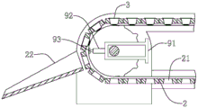
In the figure: 1. a frame; 2. a conveyor belt; 21. a groove; 22. a discharge outlet; 3. a cup body; 4. a water filtration film sealing machine; 5. a top film sealing machine; 6. a metering and filling mechanism; 61. a feeding machine; 7. an automatic cup feeding mechanism; 81. a support frame; 82. a telescopic cylinder; 83. an air inlet pipe; 84. a support plate; 841. a second vent hole; 85. a mounting seat; 86. a pressing plate; 861. a first air vent; 87. an air faucet; 88. a baffle plate; 91. a support frame; 92. a telescopic motor; 93. a flexible block; 10. spiral unloading mechanism.
Detailed Description
The present invention will be described in further detail with reference to the accompanying drawings.
In the description of the present invention, it is to be understood that the terms "upper", "lower", "left", "right", "front", "rear", "inner", "outer", and the like, indicate orientations or positional relationships based on the orientations or positional relationships shown in the drawings, are only for convenience in describing the present invention and simplifying the description, and do not indicate or imply that the device or element referred to must have a specific orientation, be constructed and operated in a specific orientation, and thus, should not be construed as limiting the present invention.
Furthermore, the terms "horizontal", "vertical" and the like do not imply that the components are absolutely horizontal or hanging, but may be slightly inclined. For example, "horizontal" merely means that the direction is more horizontal than "vertical" and does not mean that the structure must be perfectly horizontal, but may be slightly inclined.
In the description of the present invention, it should also be noted that, unless otherwise explicitly specified or limited, the terms "disposed," "connected," and "connected" are to be construed broadly, e.g., as meaning fixedly connected, detachably connected, or integrally connected; they may be mechanically coupled, directly coupled, indirectly coupled through intervening media, or may be interconnected between two elements. The specific meanings of the above terms in the present invention can be understood by those skilled in the art according to specific situations.
An embodiment, an automatic packaging machine of capsule tea, as shown in fig. 1-4, including frame 1, conveyer belt 2, cup 3, water filtration membrane capper 4, top membrane capper 5 and measurement filling mechanism 6, conveyer belt 2 locates the upper end of frame 1, equidistant recess 21 has been seted up on conveyer belt 2, each recess 21 all matches with cup 3, the right-hand member top of conveyer belt 2 is equipped with the automatic mechanism 7 of cup falling corresponding with the position of recess 21, measurement filling mechanism 6 locates the left side of automatic mechanism 7 of cup falling, the discharge gate of measurement filling mechanism 6 is corresponding with the position of recess 21, water filtration membrane capper 4 locates the left side of measurement filling mechanism 6, top membrane capper 5 locates the left side of water filtration membrane capper 4, be equipped with clear cup mechanism between water filtration membrane capper 4 and the measurement filling mechanism 6.
In detail, cup 3 places in recess 21 through automatic lower cup mechanism 7, and 2 conveyer belts carry cup 3 to loop through measurement filling mechanism 6, clear cup mechanism, water filtration membrane capper 4 and top membrane capper 5, earlier with tealeaves through measurement filling mechanism 6 filling into in cup 3, then clear cup mechanism with cup 3's rim of a cup and the tealeaves sanitization on the wall of a cup, seal cup 3 through sealing the mechanism at last.
Preferably, the cup cleaning mechanism includes a support frame 81, a telescopic cylinder 82, an air inlet pipe 83, a support plate 84, a mounting seat 85, a pressing plate 86 and an air nozzle 87, the lower end of the support frame 81 is connected to the upper end of the frame 1, the telescopic cylinder 82 is vertically arranged on the support frame 81, a base of the telescopic cylinder 82 is connected to the support frame 81, an output shaft of the telescopic cylinder 82 corresponds to the position of the groove 21, the support plate 84 is connected to an output shaft of the telescopic cylinder 82, the mounting seat 85 is hollow and has an open upper end, an open end of the mounting seat 85 is detachably connected to the lower end of the support plate 84, the air nozzle 87 is provided with a plurality of air vents and is arranged on the peripheral side of the mounting seat 85, one end of the air inlet pipe 83 penetrates through the support plate 84 and is connected to each air nozzle 87, the pressing plate 86 is arranged on the lower end of the mounting seat 85, the pressing plate 86 is matched with a cup wall of the cup body 3 where the water filtering membrane needs to be packaged, a first air vent 861 communicated with the mounting seat 85 is arranged in the middle of the pressing plate 86, and a second air vent 841 communicated with the mounting seat 85 is arranged on the support plate 84.
Specifically, the supporting frame 81 is used for supporting the telescopic cylinder 82, the telescopic cylinder 82 performs telescopic motion downwards, the telescopic cylinder 82 pushes the supporting plate 84, the mounting seat 85 and the pressing plate 86 to move downwards, when the pressing plate 86 is matched with the cup wall of the cup body 3 where the water filtering membrane needs to be sealed, the telescopic cylinder 82 stops working, at this time, the pressing plate 86 presses the tea leaves in the cup body 3 flat and seals the tea leaves in the cup body 3, the air inlet pipe 83 is connected with an air pump, high-pressure air generated by the air pump passes through the air inlet pipe 83 and is ejected out of the air nozzle 87, tea powder at the cup wall and the cup mouth is blown away, the tea leaves in the cup body 3 cannot be blown away under the protection of the pressing plate 86, the subsequent sealing of the water filtering membrane and the top membrane is ensured, and the first vent 861 and the second vent 841 facilitate the pressing of the pressing plate 86 to press the tea leaves in the cup body 3 downwards and facilitate the lifting of the pressing plate 86; after the cup body 3 is cleaned, the telescopic cylinder 82 retracts upwards, so that subsequent cup cleaning work is facilitated.
Preferably, baffles 88 are vertically disposed on the left and right sides of the supporting plate 84, the length of the baffles 88 is longer than the length of the mounting seats 85, and the lower ends of the baffles 88 contact the upper end of the conveyor belt 2 when the pressing plate 86 is matched with the cup bodies 3. Specifically, the flap 88 blocks the high-pressure air jetted from the air nozzles 87 to the left and right sides, and prevents the tea leaves in the adjacent cup 3 from being blown out.
Preferably, the mounting seat 85 is an inverted circular truncated cone with a circular arc-shaped bus and a concave shape, the air nozzle 87 is sequentially mounted on the periphery of the mounting seat 85 from top to bottom, the diameter of the lower end of the mounting seat 85 is smaller than the diameter of the cup rim of the cup body 3, and the diameter of the upper end of the mounting seat 85 is larger than the diameter of the cup rim of the cup body 3. Specifically, the lower end of the mounting seat 85 is required to extend into the cup body 3, the upper end of the mounting seat 85 is required to be positioned above the cup edge of the cup body 3, the air nozzles 87 on the mounting seat 85 are arranged in multiple rows, the uppermost row of air nozzles 87 are required to be blown to the cup edge of the cup body 3, and the lowermost row of air nozzles 87 are required to be blown to the cup wall of the cup body 3, so that the tea powder on the cup edge and the cup wall can be cleaned conveniently.
Preferably, the bottom of the groove 21 is communicated with the outside, a supporting frame 91 is arranged inside the left side of the conveyor belt 2, a horizontal leftward telescopic motor 92 is arranged on the left side of the supporting frame 91, a flexible block 93 is connected to an output shaft of the telescopic motor 92, and the output shaft of the telescopic motor 92 is used for pushing out the cup body 3 which moves to the leftmost side of the conveyor belt 2 from the groove 21. Particularly, can drop automatically from recess 21 when cup 3 moves conveyer belt 2 leftmost end, nevertheless have partly cup 3 can block in recess 21, be unfavorable for subsequent encapsulation work, and carriage 91 is used for being connected with conveyer belt 2 motionless place, and telescopic motor 92 is regular concertina movement for release cup 3 from recess 21 in following recess 21 from the below of recess 21, protection cup 3 that flexible piece 93 can be fine.
Preferably, the dosing and filling mechanism 6 is a multi-head scale. Particularly, the multi-head scale measures and fills tea leaves, and filling speed and accuracy are guaranteed.
Preferably, a spiral discharging mechanism 10 is arranged between the automatic cup discharging mechanism 7 and the metering and filling mechanism 6, and a discharging port of the spiral discharging mechanism 10 is positioned above the conveyor belt 2 and corresponds to the position of the groove 21. Specifically, the screw discharging mechanism 10 is used for filling the cup body 3 with the powdery additive.
Preferably, the left side of the conveyor belt 2 is provided with a discharge opening 22. In particular, the ejection of the sealed cup 3 is facilitated.
Preferably, a feeder 61 is arranged on the side of the frame 1, and the position of the discharge port of the feeder 61 corresponds to the position of the feed port of the metering and filling mechanism 6. Particularly, be convenient for carry tealeaves for measurement filling mechanism 6, realize automatic feeding.
The present embodiment is only for explaining the present invention, and it is not limited to the present invention, and those skilled in the art can make modifications of the present embodiment without inventive contribution as needed after reading the present specification, but all of them are protected by patent law within the scope of the claims of the present invention.

Claims (8)

1. The utility model provides an automatic packaging machine of capsule tea, includes frame (1), conveyer belt (2), cup (3), drainage membrane capper (4), plastic film capper (5) and measurement filling mechanism (6), its characterized in that: the water filtering film sealing machine is characterized in that the conveyor belt (2) is arranged at the upper end of the rack (1), grooves (21) are formed in the conveyor belt (2) at equal intervals, each groove (21) is matched with the cup body (3), an automatic cup discharging mechanism (7) corresponding to the position of each groove (21) is arranged above the right end of the conveyor belt (2), the metering filling mechanism (6) is arranged on the left side of the automatic cup discharging mechanism (7), a discharge hole of the metering filling mechanism (6) corresponds to the position of each groove (21), the water filtering film sealing machine (4) is arranged on the left side of the metering filling mechanism (6), the top film sealing machine (5) is arranged on the left side of the water filtering film sealing machine (4), and a cup cleaning mechanism is arranged between the water filtering film sealing machine (4) and the metering filling mechanism (6);
the cup cleaning mechanism comprises a support frame (81), a telescopic cylinder (82), an air inlet pipe (83), a support plate (84), a mounting seat (85), a pressing plate (86) and air nozzles (87), the lower end of the support frame (81) is connected to the upper end of the frame (1), the telescopic cylinder (82) is vertically arranged on the support frame (81), a base of the telescopic cylinder (82) is connected to the support frame (81), an output shaft of the telescopic cylinder (82) corresponds to the position of the groove (21), the support plate (84) is connected to an output shaft of the telescopic cylinder (82), the mounting seat (85) is hollow and is open at the upper end, the open end of the mounting seat (85) is detachably connected with the lower end of the support plate (84), the air nozzles (87) are provided with a plurality of air holes and mounted on the periphery of the mounting seat (85), one end of the air inlet pipe (83) penetrates through the support plate (84) and is connected to each air nozzle (87), the mounting plate (86) is arranged at the lower end of the mounting seat (85), the pressing plate (86) is communicated with a first through hole (85), the mounting seat (85) is arranged on the cup body (3), the pressing plate (86) and a water filtering membrane, the mounting seat (85) is provided with a first through hole (85), and a second through hole (85) is arranged on the pressing plate (85), the mounting seat (85), the pressing plate (85), and a second through hole is arranged on the cup body (85), the cup body (3) 841).
2. An automatic capsule tea packaging machine according to claim 1, characterized in that: the left side and the right side of the supporting plate (84) are both vertically provided with baffle plates (88), the length of the front and back direction of the baffle plates (88) is longer than that of the front and back direction of the mounting seat (85), and when the pressing plate (86) is matched with the cup body (3), the lower ends of the baffle plates (88) are in contact with the upper end of the conveying belt (2).
3. An automatic capsule tea packaging machine according to claim 1, characterized in that: mount pad (85) are the generating line and are circular-arc and inside sunken radius platform form, air cock (87) from last to installing in proper order down in week side of mount pad (85), the lower extreme diameter of mount pad (85) is less than the rim of a cup diameter of cup (3), the upper end diameter of mount pad (85) is greater than the cup limit diameter of cup (3).
4. An automatic capsule tea packaging machine according to claim 1, characterized in that: the cup body is characterized in that the bottom of the groove (21) is communicated with the outside, a supporting frame (91) is arranged inside the left side of the conveyor belt (2), a horizontal leftward telescopic motor (92) is arranged on the left side of the supporting frame (91), a flexible block (93) is connected to an output shaft of the telescopic motor (92), and an output shaft of the telescopic motor (92) is used for moving to the leftmost side of the conveyor belt (2) and pushing out the cup body (3) from the groove (21).
5. An automatic capsule tea packaging machine according to claim 1, characterized in that: the metering and filling mechanism (6) is a multi-head scale.
6. An automatic capsule tea packaging machine according to claim 1, characterized in that: a spiral discharging mechanism (10) is arranged between the automatic cup discharging mechanism (7) and the metering filling mechanism (6), and a discharging port of the spiral discharging mechanism (10) is positioned above the conveyor belt (2) and corresponds to the position of the groove (21).
7. An automatic capsule tea packaging machine according to claim 1, characterized in that: the left side of the conveyor belt (2) is provided with a discharge outlet (22).
8. An automatic capsule tea packaging machine according to claim 1, characterized in that: the side of frame (1) is equipped with feeder (61), the position of the discharge gate of feeder (61) with the position of the feed inlet of measurement filling mechanism (6) is corresponding.
CN202110324431.3A 2021-03-26 2021-03-26 Automatic capsule tea packaging machine Active CN112977914B (en)

Priority Applications (1)

Application Number Priority Date Filing Date Title
CN202110324431.3A CN112977914B (en) 2021-03-26 2021-03-26 Automatic capsule tea packaging machine

Applications Claiming Priority (1)

Application Number Priority Date Filing Date Title
CN202110324431.3A CN112977914B (en) 2021-03-26 2021-03-26 Automatic capsule tea packaging machine

Publications (2)

Publication Number Publication Date
CN112977914A CN112977914A (en) 2021-06-18
CN112977914B true CN112977914B (en) 2023-02-03

Family

ID=76333803

Family Applications (1)

Application Number Title Priority Date Filing Date
CN202110324431.3A Active CN112977914B (en) 2021-03-26 2021-03-26 Automatic capsule tea packaging machine

Country Status (1)

Country Link
CN (1) CN112977914B (en)

Families Citing this family (1)

* Cited by examiner, † Cited by third party
Publication number Priority date Publication date Assignee Title
CN114771891B (en) * 2022-06-21 2022-09-23 烟台华康生物医药科技有限公司 Sea cucumber packing plant

Citations (2)

* Cited by examiner, † Cited by third party
Publication number Priority date Publication date Assignee Title
CN103010499A (en) * 2013-01-16 2013-04-03 何立荣 Volumetric quantitive mushroom filling machine
CN212710065U (en) * 2020-07-21 2021-03-16 美灵宝现代农业股份有限公司 Cup tea filling heat-sealing mechanism of full-automatic cup tea making machine

Family Cites Families (6)

* Cited by examiner, † Cited by third party
Publication number Priority date Publication date Assignee Title
US9970424B2 (en) * 2012-03-13 2018-05-15 General Electric Company System and method having control for solids pump
CN104003001B (en) * 2013-09-12 2016-05-11 温州市沪华机械电器有限公司 Automatic coffee filling pipeline
CN114633908A (en) * 2016-07-18 2022-06-17 阿祖瑞缇医药公司 System for filling powdered medicine into one or more vials
CN208641310U (en) * 2017-12-12 2019-03-26 江西省三抗保健品有限公司 A kind of chitosan oligosaccharide capsule bottle placer
KR102182967B1 (en) * 2020-05-25 2020-11-25 지성한 Horizontal Circulation type Cup Feeding Device
CN111547317B (en) * 2020-06-02 2025-01-07 江苏神翌机械有限公司 A linear filling and sealing machine

Patent Citations (2)

* Cited by examiner, † Cited by third party
Publication number Priority date Publication date Assignee Title
CN103010499A (en) * 2013-01-16 2013-04-03 何立荣 Volumetric quantitive mushroom filling machine
CN212710065U (en) * 2020-07-21 2021-03-16 美灵宝现代农业股份有限公司 Cup tea filling heat-sealing mechanism of full-automatic cup tea making machine

Non-Patent Citations (1)

* Cited by examiner, † Cited by third party
Title
胶囊灌装系统的设计;郭锐;《品牌(下半月)》;20150323(第03期);全文 *

Also Published As

Publication number Publication date
CN112977914A (en) 2021-06-18

Similar Documents

Publication Publication Date Title
CN110638331A (en) Automatic milk tea machine
CN112977914B (en) Automatic capsule tea packaging machine
CN221987431U (en) Automatic resin feeding device for chip plastic package
CN118025725A (en) Lifting and feeding machine and method for preparing compound paracetamol and chlorphenamine maleate granules
CN202671181U (en) Container cleaning device of filling machine
CN203005829U (en) Unloading device for particle packer
CN116692159B (en) Automatic packaging equipment for capsule tea
CN105110275A (en) Method for rinsing, screening, conveying, filling and labeling pharmaceutical and chemical biological reagent bottles as well as screwing caps
CN113531372B (en) Application type system of full-automatic rotating disc type oiling machine
CN113101221A (en) Capsule filling all-in-one
CN204802108U (en) Micropill disc liquid filling machine
CN214029401U (en) Bottled ink automatic production line
CN112478294A (en) Bottled ink automatic production line
CN220056314U (en) Quantitative filling device
CN213705910U (en) Tea capsule packaging machine
CN214191478U (en) A fully automatic capping and capping machine
CN109290220B (en) A lifting pan for weighing capsule products
CN223429748U (en) A capsule filling device for drug production
CN223101582U (en) Tea powder storage device
CN212951212U (en) A unloading mechanism for straight screw rod powder packaging machine
CN223162136U (en) Crawler-type grain counting machine
CN218113042U (en) Traditional Chinese medicine pill placing device
CN220221209U (en) Filling machine for producing MCA flame retardant
CN218229466U (en) Automatic monosodium glutamate racking machine
CN208611347U (en) Pharmaceutical production device

Legal Events

Date Code Title Description
PB01 Publication
PB01 Publication
SE01 Entry into force of request for substantive examination
TA01 Transfer of patent application right

Effective date of registration: 20220927

Address after: No. 201, 2nd Floor, Building 1, Kunming Electronic Information Industry Standard Workshop (Phase 1), Plot 25, Yunjing Road Information Industry Base, Guolin Community, Luoyang Street Office, Economic Development Zone, Kunming City, Yunnan Province 650501

Applicant after: Yunnan Wuji Biotechnology Co.,Ltd.

Address before: 650215 modern international integrated logistics center, a4-6-1 plot, export processing zone, Kunming Economic Development Zone, Yunnan Province

Applicant before: Yunnan Herun Tiancheng Biotechnology Co.,Ltd.

TA01 Transfer of patent application right
GR01 Patent grant
GR01 Patent grant