Automatic pad pasting device in printed circuit board border
Technical Field
The invention belongs to the technical field of printed circuit board production, and particularly relates to an automatic film pasting device for the edge of a printed circuit board.
Background
In the production process of the printed circuit board, in order to protect four sides of the printed circuit board and prevent damage, gouge and other phenomena, a protective film is usually adhered around the circuit board, so that the protective film covers the side surfaces around the circuit board and a part of the top surface and the bottom surface close to the edges. Fix the circuit board on rotating device usually among the prior art, rotatory circuit board, then manual with the protection film winding around the circuit board, degree of automation is lower, work efficiency is not high, can not guarantee moreover that the protection film width of circuit board upper and lower is unanimous even, the protection film is too wide to let and shelter from the wiring diagram on the circuit board easily, the protection film is too narrow then can reduce the protection effect.
Disclosure of Invention
In order to solve the defects of the prior art, the invention provides the automatic film pasting device for the edge of the printed circuit board, which can automatically paste the protective films on the four edges of the circuit board, has high automation degree and high efficiency, and can ensure the width consistency of the protective films on the upper surface and the lower surface of the circuit board.
In order to realize the purpose of the invention, the following scheme is adopted:
the utility model provides an automatic pad pasting device in printed circuit board border, includes delivery track and two sets of pad pasting mechanisms, and the pad pasting mechanism sets up along the direction of delivery interval of circuit board, is equipped with commentaries on classics board mechanism and positioning mechanism along the direction of delivery of circuit board between two sets of pad pasting mechanisms in proper order.
The film sticking mechanism is arranged inside the conveying track and comprises rolling assemblies arranged on two sides of the circuit board along the conveying direction, protective film coils are arranged on the rolling assemblies in a rotating mode, a flattening roller set, a bending roller and a shaping wheel are sequentially arranged on the rolling assemblies along the conveying direction of the circuit board, protective films output by the protective film coils enter the flattening roller set from the top surface of the circuit board, and the flattening roller set compresses one part, located on the circuit board in the width direction, of the protective films on one side of the top surface of the circuit board; the bending roller is arranged above the circuit board, the axis of the bending roller is vertical to the conveying direction of the circuit board, and the bending roller bends the other part of the width of the protective film downwards along the side surface of the circuit board; the setting wheel is vertical rotation setting, and the setting wheel middle section is equipped with the ring channel that the cross-section is U type structure, and the ring channel is the bottom surface of the part direction circuit board that the protection film is bent downwards to compress tightly the protection film of circuit board top surface and bottom surface.
The roll-in subassembly rear is provided with shutdown mechanism, and shutdown mechanism includes a pair of cutter unit spare that sets up in the circuit board both sides, and cutter unit spare all is equipped with the cutter and corresponds the cutter seat that sets up with the cutter, and the cutter is located the top of pasting the protection film in circuit board both sides, and the cutter seat is located the below of pasting the protection film in circuit board both sides, and the cutter cooperates the protection film of pasting in circuit board both sides with the cutter seat when the cutter moves down and cuts off.
The rotating plate mechanism comprises a rotating plate and a pressing cover, a rotating motor is arranged at the bottom of the rotating plate and is installed above the lifting device, the pressing cover rotates to be arranged above the rotating plate, the rotating axis of the pressing cover is coaxial with that of the rotating plate, and when the circuit board is conveyed by the conveying track, the top surface of the rotating plate is lower than the conveying roller of the conveying track.
The positioning mechanism comprises a pair of side push plates which are arranged on two sides of the conveying track in a sliding mode, the sliding direction of the side push plates is horizontally perpendicular to the conveying direction of the circuit board, and the inner walls of the side push plates are parallel to the conveying direction of the circuit board.
Further, the roll-in subassembly still includes the mounting panel, and the roll set that flattens, the gyro wheel of bending and the sizing wheel are all connected in the mounting panel, and the mounting panel slides through a pair of guide arm and wears to locate delivery track's lateral wall, and the mounting panel is connected in telescoping device's push rod, and the mobile position of telescoping device control mounting panel adjusts the interval between the roll-in subassembly.
Furthermore, the flattening roller set comprises a pair of cylindrical rollers arranged on the upper side and the lower side of the circuit board, the axis of each cylindrical roller is perpendicular to the conveying direction of the printed circuit board, one part of the width direction of the protective film, which is positioned on the circuit board, of the flattening roller set is tightly pressed on the top surface of the circuit board through the cylindrical rollers positioned above the circuit board, and the cylindrical rollers positioned below the circuit board are integrally hidden at the bottom of the circuit board; the diameter of the front section cylinder of the bending roller is smaller than that of the rear section cylinder, the front section of the bending roller is positioned above the circuit board, the rear section of the bending roller is positioned on the outer side of the circuit board along the conveying direction, the included angle between the side wall of the front section of the bending roller and the inner side wall of the rear section is 90 degrees, and the projection of the tail end of the supporting roller positioned below the bending roller on the circuit board is positioned in the range of the circuit board; the juncture of the two side walls of the annular groove and the peripheral side of the shaping wheel is provided with an inclined plane along the circumference to guide the protective film, so that the protective film gradually and excessively enters the annular groove.
Further, shutdown mechanism still includes the installation pipe, and the installation pipe upwards processes there is T type groove, the direction of delivery of T type groove perpendicular to circuit board, and the cutter subassembly still includes the connecting plate of "Z" type structure, and the vertical section of connecting plate is located to the cutter seat, and the vertical propelling movement cylinder that is equipped with downwards of connecting plate top horizontal segment, cutter connection in the push rod of propelling movement cylinder, the T type inslot is located in the horizontal section slip of connecting plate bottom to utilize the screw to lock the location.
Furthermore, a plurality of conveying rollers are arranged at intervals along the axis direction of each conveying shaft of the conveying track, a plurality of through holes are processed in the rotating plate, when the rotating plate descends, the top gaps of the conveying rollers below the rotating plate penetrate through the through holes, and the peripheral sides of the pressing covers are made of rubber materials.
Further, the mounted position that the roll-in subassembly corresponds the protection film coil stock all is equipped with ejection of compact cylinder, ejection of compact cylinder passes through damping bearing and connects in the fixed axle, the protection film coil stock passes through the inner circle and connects in ejection of compact cylinder's periphery, ejection of compact cylinder has the compression sleeve through threaded connection, the external diameter that compresses tightly the cover is less than the internal diameter of protection film coil stock inner circle, the compression sleeve is equipped with a pair of spring plate along the circumference symmetry, the position processing that the compression sleeve corresponds the spring plate has the rectangular channel, the rectangular channel is located in the spring plate clearance, the terminal of spring plate inlays to be located and compresses tightly the cover, the spring plate front end outwards bulges along the normal that compresses tightly the cover, the front end that compresses tightly the cover and utilizes the spring plate compresses tightly in the terminal surface of protection film coil stock inner circle.
Further, the side push pedal is connected in telescopic cylinder's push rod, and telescopic cylinder drives the side push pedal and slides, and the bottom surface of side push pedal is less than conveying roller, and the corresponding conveying roller in side push pedal bottom all processes and has the half slot in order to dodge conveying roller.
Furthermore, the front and the rear of the cutting mechanism are respectively provided with a compression roller group, the compression roller groups comprise a pair of compression rollers arranged in the vertical direction of the circuit board, and the length of each compression roller is greater than the length and the width of the circuit board.
Furthermore, a circle of flexible material is arranged on the surface of the pressing roller.
Furthermore, the film sticking mechanism is provided with a first proximity switch and a second proximity switch at intervals along the conveying direction of the circuit boards so as to control the spacing distance between the adjacent circuit boards along the conveying direction, and the cutting mechanism is provided with a third proximity switch so as to determine the cutting position of the protective film.
The invention has the beneficial effects that:
1. utilize the delivery track to carry the circuit board, be equipped with two sets of pad pasting mechanisms along the delivery track, first set of pad pasting mechanism carries out pasting of protection film to circuit board wherein arbitrary relative both sides, the second of delivery track rear end is organized pad pasting mechanism and is carried out pasting of protection film to another relative both sides of circuit board, it carries out 90 rotations to the circuit board to be equipped with between first set of pad pasting mechanism and the second group pad pasting mechanism and change the board mechanism, the both sides that make the circuit board be for pasting the protection film are in direction of delivery's both sides, the circuit board advances to be fixed a position through positioning mechanism before the second group pad pasting mechanism, make the circuit board organize the import of pad pasting mechanism to its second, whole journey all adopts automatic smooth realization, artifical participation is few, can greatly improve production efficiency.
2. The film sticking mechanism stably sticks the protective film on the upper and lower surfaces of the circuit board when the protective film is gradually shaped through the flattening roller set, the bending roller and the shaping wheel which are arranged on the two sides of the circuit board, firstly, the sticking width of the top surface of the circuit board is fixed through the flattening roller set, and the protective film is tightly pressed; then the protective film deforms towards the lower part of the circuit board when the bending roller is used, the other part of the protective film in the width direction gradually approaches to the bottom surface of the circuit board when the protective film passes through the annular groove of the shaping wheel, and meanwhile the protective film below the circuit board is preliminarily pressed by the inner wall of the annular groove. The pasting width of the protective film on the top surface of the circuit board can be controlled by controlling the position of the protective film roll material along the axis direction of the flattening roller set, then the protective film is bent at the preset width position of the protective film by utilizing the bending roller, and the shaping wheel guides the protective film at the preset width position to the bottom surface of the circuit board, so that the pasting width of the protective film on the upper surface and the lower surface of the circuit board is more controllable.
3. Because the protection film is the consumptive material, need often change the protection film coil stock, for the change of protection film coil stock, designed dedicated compressing tightly the cover, all need not take out completely compressing tightly the cover and can accomplishing when the installation with demolising the protection film coil stock, effectively improved the change efficiency of protection film coil stock.
4. The distance between the rolling component and the cutter component can be adjusted, the rolling component and the cutter component can be used for pasting protective films of circuit boards with different widths and different length sizes, and meanwhile, the working principle of the side pushing plate has the width adjusting function, so that the circuit boards with different widths and different length sizes can be positioned.
Drawings
The drawings described herein are for illustrative purposes only of selected embodiments and not all possible implementations, and are not intended to limit the scope of the present disclosure.
FIG. 1 shows the overall construction of the present application;
FIG. 2 shows the configuration of the film sticking mechanism and the rotating plate mechanism and the positioning mechanism;
FIG. 3 shows a partial enlarged view at A in FIG. 2;
FIG. 4 shows a bottom view of the delivery track;
FIG. 5 is a configuration diagram showing a film attaching mechanism;
FIG. 6 is a schematic view showing the construction and operation of the leveling roller group;
FIG. 7 is a schematic view showing the structure and operation of a bending roller;
FIG. 8 is a schematic view showing the structure and operation of the sizing wheel;
FIG. 9 shows a partial enlarged view at B in FIG. 5;
FIG. 10 shows the construction and installation of the take-off drum and the clamping sleeve;
FIG. 11 shows a cross-sectional view of the compression sleeve taken along the line A-A in FIG. 10;
FIG. 12 is a configuration diagram showing a cutting mechanism;
FIG. 13 is a state diagram showing a circuit board entering the film attaching mechanism;
fig. 14 is a view showing a state where the protective film of the side of the circuit board is at the position of the cutting structure;
FIG. 15 shows a partial enlarged view at C in FIG. 14;
FIG. 16 is a view showing the circuit board after being rotated by the rotating plate mechanism;
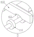
fig. 17 shows a partial enlarged view at D in fig. 16.
The labels in the figure are: a circuit board-1, a protective film coil-2, a protective film-3, a first proximity switch-4, a second proximity switch-5, a third proximity switch-6, a conveying track-100, a conveying roller-110, a conveying shaft-120, a film pasting mechanism-200, a rolling component-210, a flattening roller set-220, a cylindrical roller-221, a bending roller-230, a supporting roller-231, a shaping roller-240, an annular groove-241, an inclined surface-242, a cutting mechanism-250, a cutter component-251, a cutter-252, a cutter seat-253, a mounting pipe-254, a T-shaped groove-2541, a connecting plate-255, a pushing cylinder-256, a mounting plate-260, a guide rod-261, a telescopic device-262, a discharging roller-270, a feeding roller-270, Damping bearing-271, fixed shaft-272, pressing sleeve-280, rectangular groove-2801, spring plate-281, pressing roller group-290, pressing roller-291, rotating plate mechanism-300, rotating plate-310, through hole-311, pressing cover-320, rotating motor-330, lifting device-340, positioning mechanism-400, side pushing plate-410, semicircular groove-411 and telescopic cylinder-420.
Detailed Description
In order to make the objects, technical solutions and advantages of the embodiments of the present invention clearer, the following detailed description of the embodiments of the present invention is provided with reference to the accompanying drawings, but the described embodiments of the present invention are a part of the embodiments of the present invention, not all of the embodiments of the present invention.
It should be noted that: like reference numbers and letters refer to like items in the following figures, and thus, once an item is defined in one figure, it need not be further defined and explained in subsequent figures.
In the description of the present invention, it should be noted that the terms "center", "upper", "lower", "left", "right", "vertical", "horizontal", "inner", "outer", and the like indicate orientations or positional relationships based on the orientations or positional relationships shown in the drawings or orientations or positional relationships that the products of the present invention are usually placed in when used, and are only for convenience of describing the present invention and simplifying the description. The terms "first," "second," and the like are used solely to distinguish one from another and are not to be construed as indicating or implying relative importance. The terms "parallel", "perpendicular", etc. do not require that the components be absolutely parallel or perpendicular, but may be slightly inclined.
In the description of the present invention, it should also be noted that, unless otherwise explicitly specified or limited, the terms "disposed," "mounted," "connected," and "connected" are to be construed broadly, e.g., as meaning either a fixed connection, a removable connection, or an integral connection; either directly or indirectly through intervening media, or through both elements. The specific meanings of the above terms in the present invention can be understood by those skilled in the art according to specific situations.
Specifically, as shown in fig. 1, an automatic film pasting device for printed circuit board edges includes a conveying track 100 and two sets of film pasting mechanisms 200, the film pasting mechanisms 200 are arranged at intervals along the conveying direction of the circuit board 1, the first set of film pasting mechanisms 200 arranged at the front end of the conveying track 100 are used for pasting protective films 3 on any two opposite sides of the circuit board 1, and the second set of film pasting mechanisms 200 arranged at the rear end of the conveying track 100 are used for pasting protective films 3 on the other two opposite sides of the circuit board 1. A rotating plate mechanism 300 and a positioning mechanism 400 are sequentially arranged between the two film sticking mechanisms 200 along the conveying direction of the circuit board 1. The board rotating mechanism 300 rotates the circuit board 1 by 90 °, and the positioning mechanism 400 positions the circuit board 1 before entering the second set of film pasting mechanisms 200, so as to ensure that the circuit board 1 is aligned with the inlet of the second set of film pasting mechanisms 200.
Specifically, as shown in fig. 1 and 5, the film pasting mechanism 200 is disposed inside the conveying track 100, the film pasting mechanism 200 includes rolling assemblies 210 disposed on two sides of the circuit board 1 along the conveying direction, the rolling assemblies 210 are all rotatably provided with a protective film roll 2, the rolling assemblies 210 are sequentially provided with a flattening roller set 220, a bending roller 230 and a shaping wheel 240 along the conveying direction of the circuit board 1, a protective film 3 output by the protective film roll 2 enters the flattening roller set 220 from the top surface of the circuit board 1, the flattening roller set 220 compresses a part of the protective film 3 located on the circuit board 1 in the width direction to one side of the top surface of the circuit board 1, and the other part of the protective film 3 in the width direction is in a suspended state; the bending roller 230 is arranged above the circuit board 1, the axis of the bending roller 230 is vertical to the conveying direction of the circuit board 1, and the bending roller 230 bends the other part of the protective film 3, which is positioned on the circuit board 1 in the width direction, downwards along the side surface of the circuit board 1; the shaping wheel 240 is vertically and rotatably arranged, an annular groove 241 with a U-shaped section is arranged at the middle section of the shaping wheel 240, the annular groove 241 guides the downward bent part of the protective film 3 to the bottom surface of the circuit board 1, and the top surface of the circuit board 1 and the protective film 3 on the bottom surface are tightly pressed;
specifically, as shown in fig. 2, 12 and 15, a cutting mechanism 250 is disposed behind the rolling assembly 210, the cutting mechanism 250 includes a pair of cutter assemblies 251 disposed on two sides of the circuit board 1, each cutter assembly 251 is provided with a cutter 252 and a cutter seat 253 disposed corresponding to the cutter 252, the cutter 252 is disposed above the protective films 3 adhered on two sides of the circuit board 1, the cutter seat 253 is disposed below the protective films 3 adhered on two sides of the circuit board 1, and the cutter 252 cooperates with the cutter seats 253 to cut off the protective films 3 adhered on two sides of the circuit board 1 when moving downward;
specifically, the rotating plate mechanism 300 includes a rotating plate 310 and a pressing cover 320, the bottom of the rotating plate 310 is provided with a rotating motor 330, the rotating motor 330 is installed above the lifting device 340, the pressing cover 320 is rotatably installed above the rotating plate 310, the rotating axis of the pressing cover 320 is coaxial with the rotating axis of the rotating plate 310, and when the circuit board 1 is conveyed by the conveying track 100, the top surface of the rotating plate 310 is lower than the conveying rollers 110 of the conveying track 100;
specifically, the positioning mechanism 400 includes a pair of side push plates 410 slidably disposed on two sides of the conveying track 100, a sliding direction of the side push plates 410 is horizontally perpendicular to a conveying direction of the circuit board 1, the pair of side push plates 410 are disposed on two sides of the conveying direction of the circuit board 1, and an inner wall of the side push plates 410 is parallel to the conveying direction of the circuit board 1.
More specifically, as shown in fig. 5, the rolling assembly 210 further includes a mounting plate 260, the flattening roller set 220, the bending roller 230 and the sizing wheel 240 are all connected to the mounting plate 260, the mounting plate 260 is slidably disposed through the side wall of the conveying track 100 by a pair of guide rods 261, the mounting plate 260 is connected to a push rod of a telescopic device 262, the telescopic device 262 controls the moving position of the mounting plate 260, the distance between the rolling assemblies 210 is adjusted to work with the film pasting on the edges of the circuit boards 1 with different widths and length sizes by adjusting the distance between the rolling assemblies 210, the distance between the rolling assemblies 210 is automatically adjusted by the telescopic device 262 during moving, and the stability of the rolling assemblies 210 during moving is improved by using the two guide rods 261.
More specifically, as shown in fig. 6, the flattening roller set 220 includes a pair of cylindrical rollers 221 disposed on the upper and lower sides of the circuit board 1 along the same vertical plane, the axis of the cylindrical roller 221 is perpendicular to the conveying direction of the printed circuit board 1, the flattening roller set 220 presses a portion of the protective film 3 located on the circuit board 1 in the width direction against the top surface of the circuit board 1 through the cylindrical roller 221 located above the circuit board 1, the cylindrical roller 221 located below the circuit board 1 is entirely hidden at the bottom of the circuit board 1, and the other portion of the protective film 3 in the width direction is prevented from being stuck on the cylindrical roller 221 below the circuit board 1, as shown in the figure, the length of the cylindrical roller 221 located below the circuit board 1 is shorter than the length of the cylindrical roller 221 above the circuit board 1.
More specifically, as shown in fig. 7, the diameter of the front section cylinder of the bending roller 230 is smaller than the diameter of the rear section cylinder, the front section of the bending roller 230 is located above the circuit board 1, the rear section of the bending roller 230 is located outside the circuit board 1 along the conveying direction, the included angle between the front section side wall of the bending roller 230 and the rear section inner side wall is 90 °, the included angle formed by the front section side wall of the bending roller 230 and the rear section inner side wall enables the protective film 3 to form a downward 90 ° bend, the projection of the end of the supporting roller 231 located below the bending roller 230 on the circuit board 1 is located within the range of the circuit board 1, the bent protective film 3 is spaced from the end face of the supporting roller 231, and the protective film 3 is prevented from being stuck on the end face of the supporting roller 231.
Preferably, as shown in fig. 8, inclined surfaces 242 are machined along the circumference at the junctions between the two side walls of the annular groove 241 and the peripheral side of the sizing wheel 240, so as to guide the protective film 3 and enable the protective film 3 to gradually and excessively enter the annular groove 241.
Preferably, as shown in fig. 12, the cutting mechanism 250 further includes a mounting tube 254, a T-shaped groove 2541 is formed upwards in the mounting tube 254, the T-shaped groove 2541 is perpendicular to the conveying direction of the circuit board 1 and is parallel to the plane of the circuit board 1, the cutter assembly 251 further includes a connecting plate 255 having a "Z" -shaped structure, the connecting plate 255 includes a vertical section and a horizontal section respectively disposed at the top and the bottom of the vertical section, and the vertical section is perpendicular to the horizontal section. The cutter seat 253 is arranged on a vertical section of the connecting plate 255, a pushing cylinder 256 is vertically and downwards arranged on a transverse section of the top of the connecting plate 255, the cutter 252 is connected to a push rod of the pushing cylinder 256, the transverse section of the bottom of the connecting plate 255 is slidably arranged in the T-shaped groove 2541 and is locked and positioned by screws, and when circuit boards 1 with different widths or different lengths are produced, the position of the cutter component 251 in the T-shaped groove 2541 can be adjusted to correspond to each other.
Preferably, as shown in fig. 2 and 3, a plurality of conveying rollers 110 are arranged at intervals along the axial direction of each conveying shaft 120 of the conveying track 100, a plurality of through holes 311 are formed in the rotating plate 310, when the rotating plate 310 descends, a gap between the tops of the conveying rollers 110 below the rotating plate 310 passes through the through holes 311, the portion of the tops of the conveying rollers 110 passing through the through holes 311 is used for supporting and conveying the circuit board 1, and meanwhile, the circuit board 1 and the rotating plate 310 are spaced from each other, the circumferential side of the pressing cover 320 is made of rubber, which not only can prevent the circuit board 1 from being crushed, but also can add friction between the pressing cover 320 and the circuit board 1, and prevent the pressing cover 320 and the circuit board 1 from rotating relatively.
Preferably, as shown in fig. 9 to 11, the roll pressing assembly 210 is provided with a discharging roller 270 corresponding to the mounting position of the protective film roll 2, the discharging roller 270 is connected to a fixed shaft 272 through a damping bearing 271, the fixed shaft 272 is connected to the mounting plate 260 through a plate, and the damping bearing 271 with a damping force is used for connection, so that the protective film roll 2 can be prevented from being continuously pulled by the residual force of pulling the protective film 3, and the protective film 3 is pulled out too much, thereby not only easily adhering the pulled protective film 3 around, but also reducing the pulling force of the protective film, easily making the protective film 3 wrinkle on the circuit board 1, and affecting the adhesion effect on the edge of the circuit board 1, the protective film roll 2 is connected to the periphery of the discharging roller 270 through an inner ring, the discharging roller 270 is connected with a pressing sleeve 280 through a screw thread, the outer diameter of the pressing sleeve 280 is smaller than the inner diameter of the inner ring of the protective film roll 2, so as to load and unload the protective film roll 2, a pair of spring plates 281 are symmetrically arranged along the circumference of the pressing sleeve 280, a rectangular groove 2801 is processed at the position of the pressing sleeve 280 corresponding to the spring plates 281, a gap between the spring plates 281 is arranged in the rectangular groove 2801, the tail end of the spring plate 281 is embedded in the pressing sleeve 280, the front end of the spring plate 281 protrudes outwards along the normal line of the pressing sleeve 280, the pressing sleeve 280 presses the end surface of the inner ring of the protective film coil 2 by using the front end of the spring plate 281, when the front end of the spring plate 281 is pressed inwards along the normal line of the pressing sleeve 280, the front end of the spring plate 281 is embedded in the rectangular groove 2801, at the moment, the front end of the spring plate 281 is separated from the end surface of the inner ring of the protective film coil 2, and the inner ring of the protective film coil 2 can be taken out under the state that the pressing sleeve 280 is not taken out; when the protective film roll material 2 is installed, the pressing sleeve 280 only needs to rotate for a certain distance towards the tail end of the discharging roller 270, then the protective film roll material 2 is directly inserted into the pressing sleeve 280 and the discharging roller 270, in the process that the pressing sleeve 280 penetrates through the protective film roll material 2, the front end of the spring plate 281 is pressed by the inner ring of the protective film roll material 2 and is pressed into the rectangular groove 2801, after the protective film roll material 2 passes over the pressing sleeve 280, the front end of the spring plate 281 can automatically recover elasticity, and then the pressing sleeve 280 is rotated towards the discharging roller 270, so that the front end of the spring plate 281 can be pressed on the inner ring of the protective film roll material 2.
Preferably, as shown in fig. 16 and 17, the side pushing plate 410 is connected to a pushing rod of a telescopic cylinder 420, the telescopic cylinder 420 drives the side pushing plate 410 to slide, a bottom surface of the side pushing plate 410 is lower than the conveying roller 110 to prevent the side edge of the circuit board 1 from being clamped in a gap between the side pushing plate 410 and the conveying roller 110 when the circuit board 1 is pushed, and a semicircular groove 411 is formed at the bottom of the side pushing plate 410 corresponding to the conveying roller 110 to avoid the conveying roller 110.
Preferably, as shown in fig. 2 and 4, the pinch roller set 290 is disposed at the front and rear of the cutting mechanism 250, as shown in fig. 5, the pinch roller set 290 includes a pair of pinch rollers 291 disposed at the upper and lower direction of the circuit board 1, the pinch rollers 291 pinch the protective films 3 at both sides of the circuit board 1, and the length of the pinch rollers 291 is greater than the length and width of the circuit board 1.
Further preferably, the surface of the pressing roller 291 is provided with a circle of flexible material to prevent the circuit board 1 from being damaged by pressure, and meanwhile, the protective film 3 can be pressed more tightly by utilizing the elastic characteristics of the elastic material, and the flexible material can select rubber and fluff back cotton cloth.
More specifically, as shown in fig. 2 and 4, the film attaching mechanism 200 is provided with a first proximity switch 4 and a second proximity switch 5 at an interval in the conveying direction of the circuit boards 1 to control the interval distance between the adjacent circuit boards 1 in the conveying direction, and the cutting mechanism 250 is provided with a third proximity switch 6 to determine the cutting position of the protective film 3.
The specific implementation mode is as follows:
the circuit board 1 is put in from the first group of film sticking mechanisms 200 at the front end of the conveying track 100, before the protective film 3 is stuck on the first circuit board 1, the protective films 3 on the two sides are firstly pulled out from the protective film roll material 2, so that the front end of the protective film 3 passes through the cylindrical rollers 221, then the circuit board 1 can be put in, and the circuit board 1 can be sent in by adopting a conveying line conveying mode to improve the efficiency. When the circuit board 1 enters between the cylindrical rollers 221, the protective film 3 starts to contact with the top surface of the circuit board 1, after the circuit board 1 passes through the cylindrical rollers 221, the protective film 3 on the top surface is adhered to the surface of the circuit board 1, the protective film 3 is slowly pulled out along with the movement of the circuit board 1, and then the circuit board 1 finishes the work of adhering the protective films on the two sides of the circuit board 1 sequentially through the bending rollers 230 and the shaping rollers (240). The circuit board 1 continues to move forward until the state shown in fig. 13 appears, the rear end of the circuit board 1 leaves the detection range of the second proximity switch 5, and the circuit board 1 stops moving; until the front end of the circuit board 1 at the back moves to the detection range of the first proximity switch 4, and then the two adjacent circuit boards 1 move forwards simultaneously, so as to control the spacing distance between the two adjacent circuit boards 1. As shown in fig. 14 and 15, when the circuit board 1 with the protective films 3 adhered to both sides moves to a detection range of the third proximity switch 6, the cutter blade 252 moves downward, and at this time, the front end of the circuit board 1 and the projection of the cutter blade 252 on the bottom surface have a predetermined distance, and the protective films 3 on both sides are cut by the cooperation of the cutter blade 252 and the cutter seat 253. Then, the circuit board 1 continues to move forward to above the rotating plate 310, the lifting device 340 lifts the rotating motor 330 and the rotating plate 310 upwards together, the circuit board 1 is lifted through the rotating plate 310, so that the bottom of the rotating plate 310 is separated from the conveying roller 110, when the top surface of the circuit board 1 is contacted and pressed with the bottom of the pressing cover 320, as shown in fig. 16, the rotating motor 330 drives the rotating plate 310 and the circuit board 1 to move and rotate 90 degrees, and the pressing cover 320 rotates along with the rotating plate; then the lifting device 340 lowers the rotating motor 330 and the rotating plate 310 together with the circuit board 1, so that the circuit board 1 contacts with the conveying roller 110; the circuit board 1 continues to move forward to the positioning mechanism 400, the side push plates 410 positioned at the two sides push the circuit board 1 to a preset position towards the middle part, and then the side push plates 410 retract towards the two sides; the second set of film sticking mechanisms 200, which are arranged at the rear end of the conveying track 100, are used for continuously moving the circuit board 1 to stick the protective film 3 to the other opposite side surface, and the working principle of the second set of film sticking mechanisms 200 is the same as that of the first set of film sticking mechanisms 200. After the second set of film pasting mechanism 200 pastes the protection film 3 on the remaining two sides of the circuit board 1, the protection film 3 is cut by the cutting mechanism 250, and the circuit board 1 can be automatically output through the conveying track 100.
The foregoing is only a preferred embodiment of the present invention and is not intended to be exhaustive or to limit the invention. It will be understood by those skilled in the art that various changes may be made and equivalents may be substituted without departing from the scope of the invention.