Automatic reagent tube sample conveying and bundling device
Technical Field
The invention relates to the technical field of medical auxiliary instruments, in particular to a reagent tube sample feeding automatic bundling device.
Background
In a medical unit, logistics, property and sanitation personnel of a hospital often need to be responsible for and arrange sample sending work of various patient sample tissues, the various sample tissues are basically placed in a reagent tube with a sealing cover for transportation at present, and blood examination is the most frequent biological sample examination mode at present because various biological index data contained in blood are the most detailed.
Before blood examination, medical personnel can draw a plurality of reagent tube amounts of liquid of a patient according to the examination required. In general, a medical staff performing a blood drawing work manages blood by manually bundling all reagent tubes containing the same patient with rubber bands.
However, the medical staff has the following disadvantages in the actual operation process:
firstly, medical personnel are at the manual in-process of tying up a plurality of reagent pipes with annular elasticity strapping, because the surface of reagent pipe is comparatively smooth for it slides or drops to take place for the rubber band of in-process of tying up, makes medical personnel need readjust the position or tie up again, can consume medical personnel's time and energy.
Two, medical personnel need a hand to grasp same patient's whole blood reagent pipe after having extracted blood, and the rubber band is taken to another hand and is fixed, if same patient's reagent pipe quantity is when more, medical personnel can't grasp with stabilizing completely on one hand and hold, at the in-process of tying up, the reagent pipe is easy to follow medical personnel's hand landing, cause easily to break away from between reagent pipe and the reagent tube cap, lead to the intraductal blood of reagent to flow, cause blood extravagant and pollution.
Thirdly, medical personnel need pile up all reagent pipes to a department with the blood of same patient with annular elasticity strapping tape at manual in-process of tying up a plurality of reagent pipes with annular elasticity strapping tape, then strut annular elasticity strapping tape, can be enough to pile up reagent pipe and tie up until the big or small degree of annular elasticity strapping tape, again encircle the periphery that reagent pipe piled up with annular elasticity strapping tape, loosen annular elasticity strapping tape at last and accomplish and tie up, medical personnel's time and energy consumption are more.
And the loose or unbounded sample reagent tube is easy to be mixed in the transportation process of the logistics cleaning personnel (hereinafter referred to as logistics personnel), and after the reagent tube falls off, part of samples contain infectious pathogens, so that the risk of iatrogenic infection exists for the logistics personnel.
Disclosure of Invention
The invention aims to provide a reagent tube sample feeding automatic bundling device which can store a plurality of annular bundling belts simultaneously, can bundle a plurality of reagent tubes quickly, does not need medical staff to bundle reagent tube stacks by using annular elastic bundling belts manually, reduces the working strength of the medical staff and improves the working efficiency of the medical staff.
In order to realize the purpose of the invention, the invention adopts the following technical scheme:
a reagent tube sample feeding automatic bundling device comprises a machine body, a base used for placing an elastic annular bundling belt, a conveying mechanism and a bundling mechanism, wherein the conveying mechanism and the bundling mechanism are arranged in the machine body;
the conveying mechanism comprises a central column and a plurality of rotary rods, the central column is arranged above the base, the connecting ends of the rotary rods are rotatably connected to the peripheral side of the central column, and the movable end of the other end of each rotary rod is positioned in the middle of an annular strapping tape placed on the base; the base is provided with a telescopic column, the telescopic column is arranged in the middle of the base and is positioned below the central column, the annular strapping tape is sleeved outside the telescopic column, and the movable end of the rotating rod is positioned between the telescopic column and the annular strapping tape;
the rotary rods are uniformly arranged at intervals on the outer side of the central column, the bundling mechanism comprises a plurality of synchronously rotating conveying belts and a plurality of baffles, the conveying belts are vertically arranged in the machine body, the baffles are uniformly arranged on the conveying belts at intervals, and hooks are arranged on the sides of the baffles far away from the conveying belts;
the rotary rod is further provided with a clamping groove used for clamping the annular strapping tape, and when the rotary rod is pushed to the highest point by the telescopic column, the hook is located in the clamping groove.
Compared with the prior art, the reagent tube sample feeding automatic binding device adopting the technical scheme has the following beneficial effects:
according to the reagent tube sample feeding automatic bundling device, a plurality of reagent tubes to be bundled are placed in the bundling device, the annular bundling belt placed on the base is transmitted to the bundling mechanism through the transmission mechanism, medical workers only need to place the plurality of reagent tubes in the bundling device, the annular bundling belt is sleeved on the plurality of reagent tubes through shifting the hooks corresponding to the baffles on the transmission belt, the medical workers do not need to manually open the elastic annular bundling belt and then manually place the reagent tubes in the annular bundling belt, the labor time of the medical workers is saved, and the working efficiency of a blood examination and blood drawing window is improved.
And secondly, a plurality of annular strapping tapes can be placed on the chassis in advance, and then the annular strapping tapes are used for strapping reagent tubes under the driving of the conveying mechanism, so that the step of frequently adding the annular strapping tapes into the strapping device is omitted, a large amount of time is saved, and the working strength of medical personnel is reduced.
Thirdly, the convenience of conveying the tissue samples by the logistics personnel is improved, the conveying efficiency is improved, and meanwhile, the possibility of iatrogenic infection is effectively avoided.
Preferably, be equipped with in the organism and be used for placing the tub dish of putting of reagent pipe, it sets up to put the tub dish the top of center post, put the pipe dish week side with be equipped with the clearance between the organism, the even interval of conveyer belt sets up in the clearance, the baffle is equipped with one side orientation of couple and puts the tub dish setting, the dish mouth periphery of putting the tub dish is equipped with protruding eaves, the baffle moves under the drive of conveyer belt during the protruding eaves position, protruding eaves makes the baffle take place to deform with the couple partial contact on the corresponding baffle.
The conveyer belt drives the baffle plate on the conveyer belt to pass through the convex eaves on the outer side of the pipe placing disc in the upward rotating process, the hook is blocked by the convex eaves, the baffle plate is driven to deform, the annular strapping tape on the corresponding baffle plate is separated from the hook and shrinks towards the direction of the reagent pipes from the upper part of the pipe placing disc, and finally the annular strapping tape is bundled on the reagent pipes, so that the height of the pipe placing disc is the height of the annular strapping tape bundled on the reagent pipes. The convex eaves outside the tube placing disc are utilized to guarantee that the annular strapping tape in the strapping device is automatically bound on the reagent tube in the running process of the conveying belt, so that the medical personnel are prevented from manually stirring the hook.
Preferably, still include interlock mechanism, interlock mechanism is including triggering the piece, be used for driving the first linkage subassembly of conveyer belt operation and be used for driving the second linkage subassembly of rotary rod motion, trigger the piece setting in the organism outside, when triggering the piece and being triggered once, conveyer belt pivoted distance is the distance between two adjacent baffles, simultaneously the rotary rod rotates once to the upward movement.
The purpose of transferring annular bands one by one between the conveying mechanism and the bundling mechanism is guaranteed by the linkage mechanism, and the annular bundling bands are prevented from being arranged on hooks, which are in contact with the convex eaves, of the conveying belt.
Preferably, the first linkage assembly comprises a linkage rod and a transmission wheel provided with a plurality of transmission teeth, and the transmission wheel is coaxially and rotatably arranged with one end of the transmission belt; the machine body is provided with a slot, one end of the linkage rod is connected with the trigger, the other end of the linkage rod penetrates through the slot and is positioned in the transmission teeth of the conveying wheel, and the end part of the linkage rod, which is close to the trigger, is rotatably connected to the slot of the machine body.
Preferably, a cavity is arranged in the base and is arranged along the diameter of the base; the telescopic column comprises a telescopic seat and a telescopic piece, the telescopic seat is arranged on the base, a cylindrical hole is formed in the telescopic seat, the telescopic piece is positioned in the cylindrical hole, two ends of the cavity are respectively linked to the outer side of the base and are exposed out of the machine body, and the middle of the cavity is communicated with the cylindrical hole;
the second linkage assembly comprises a longitudinal transmission member and a transverse transmission member, the longitudinal transmission member is longitudinally arranged at the end part of the cavity, and the transverse transmission member is transversely arranged in the cavity; one end of the longitudinal transmission member is exposed outside the cavity and is in contact with the trigger member, the other end of the longitudinal transmission member is in contact with the end part of the transverse transmission member, and the bottom of the telescopic member is in contact with the end part of the transverse transmission member;
the contact surfaces of the longitudinal transmission member and the transverse transmission member and the contact surfaces of the transverse transmission member and the telescopic member are obliquely arranged transmission surfaces; when the longitudinal transmission member moves downwards, the transverse transmission member moves to the position of the telescopic seat and drives the telescopic column to move upwards.
Preferably, the trigger member is arranged in an annular shape, the trigger member is sleeved outside the machine body, a plurality of grooves are formed in the machine body, the positions of the grooves correspond to the positions of the conveyor belts, and the number of the first linkage assemblies is the same as the number of the conveyor belts.
Preferably, the bottom of the pipe placing disc is provided with a supporting leg, one end of the supporting leg is fixed at the bottom of the pipe placing disc, and the other end of the supporting leg is fixed on the telescopic seat.
Preferably, the organism is cylindrical setting, the conveyer belt the rotary rod with first linkage assembly all is equipped with four, and adjacent contained angle is ninety degrees.
Drawings
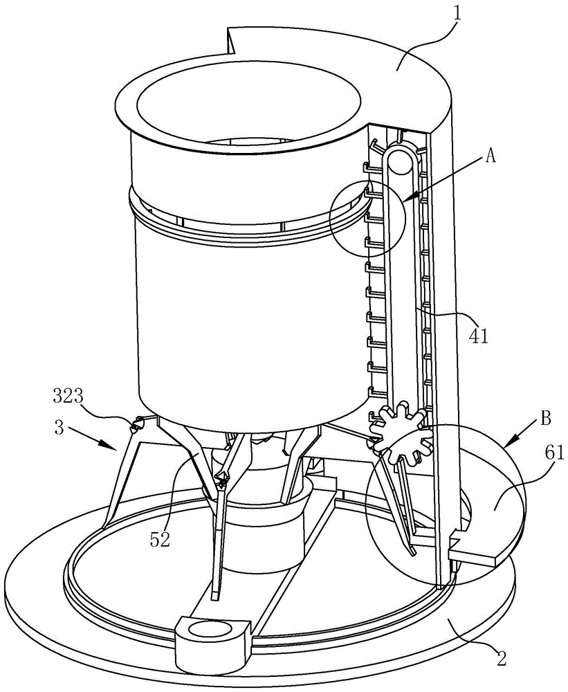
FIG. 1 is a schematic structural diagram of an embodiment of an automatic reagent tube sample feeding and binding apparatus according to the present invention.
Fig. 2 is a schematic structural view of the interior of the housing in the embodiment.
Fig. 3 (a) - (b) are schematic diagrams illustrating different states of the transmission structure in the embodiment.
Fig. 4 (a) - (b) are schematic structural views of different states of the conveying mechanism and the binding mechanism in the embodiment.
Fig. 5 is a sectional view of the embodiment.
Fig. 6 is an enlarged schematic view of a point a in fig. 5.
FIGS. 7 (a) - (c) are schematic structural views of different states between the tube placing disk and the baffle in the embodiment.
Fig. 8 is an enlarged schematic view at B in fig. 5.
FIG. 9 is a schematic structural diagram of a second transmission assembly in different states according to an embodiment.
Reference numerals: 1. a body; 11. grooving; 2. a base; 21. a telescopic column; 211. a telescopic base; 211a, cylindrical holes; 212. a telescoping member; 22. a cavity; 3. a transport mechanism; 31. a central column; 32. rotating the rod; 321. a connecting end; 322. a movable end; 323. a card slot; 4. a strapping mechanism; 41. a conveyor belt; 42. a baffle plate; 421. hooking; 5. placing a pipe disc; 51. a convex brim; 52. supporting legs; 61. a trigger; 62. a first linkage assembly; 621. a linkage rod; 622. a transfer wheel; 63. a second linkage assembly; 631. a longitudinal drive member; 632. a transverse transmission member; 633. a driving surface; 10. and (4) a ring-shaped strapping tape.
Detailed Description
The invention is further described below with reference to the accompanying drawings.
As shown in fig. 1 to 9, in the reagent tube sample feeding automatic binding apparatus, after a medical staff vertically places a plurality of reagent tubes in the tube placing tray 5, and presses the trigger 61, the automatic binding apparatus in this embodiment can eject an annular binding band 10 from a gap between the tube placing tray 5 and the machine body 1, and the annular binding band 10 has elasticity and can fix the plurality of reagent tubes to each other.
Fig. 2 is a schematic diagram of the mechanism inside the machine body 1, which includes a base 2 for placing an elastic annular binding belt 10, a conveying mechanism 3 and a binding mechanism 4 arranged in the machine body 1, wherein the binding mechanism 4 is positioned above the conveying mechanism 3; the conveying mechanism 3 comprises a central column 31 and a plurality of rotating rods 32, the central column 31 is arranged above the base 2, the connecting ends 321 of the rotating rods 32 are rotatably connected on the peripheral side of the central column 31, and the movable ends 322 of the other ends of the rotating rods 32 are positioned in the middle of the annular strapping tape 10 placed on the base 2. The base 2 is provided with a telescopic column 21, the telescopic column 21 is arranged in the middle of the base 2 and is located below the central column 31, the annular strapping tape 10 is sleeved outside the telescopic column 21, the bottom of the pipe placing disc 5 is provided with a supporting leg 52, one end of the supporting leg 52 is fixed at the bottom of the pipe placing disc 5, and the other end of the supporting leg 52 is fixed on the telescopic seat 211.
As shown in fig. 2 and fig. 3 (a) and 3 (b), in the present embodiment, the strapping mechanism 4 includes four rotating rods 32, and can spread the endless strapping band 10 evenly from four directions. As shown in fig. 3 (a), the rotating rod 32 is in the initial state, the direction of the arrow on the rotating rod 32 is the rotating direction of the slot 323 on the rotating rod 32, and at this time, the movable end 322 of the rotating rod 32 is located between the telescopic post 21 and the annular strapping tape 10, and when the telescopic member 212 in the telescopic seat 211 moves upward along the direction of the arrow in fig. 3 (b), the rotating rod 32 is driven to rotate, and at this time, one annular strapping tape 10 on the chassis is lifted up and is spread by four rotating rods 32. When the rotating rod 32 is spread to a certain extent, the loop strap 10 moves along the rotating rod 32 toward the catching groove 323 due to the elasticity of the loop strap 10.
As shown in fig. 4 (a) - (b), the bundling mechanism 4 includes a plurality of synchronously rotating conveyor belts 41 and a plurality of baffles 42, the conveyor belts 41 are vertically disposed in the machine body 1, the baffles 42 are uniformly spaced on the conveyor belts 41, and hooks 421 are disposed on the sides of the baffles 42 far away from the conveyor belts 41; the rotating rod 32 is further provided with a locking groove 323 for locking the annular strapping tape 10, and when the rotating rod 32 is pushed to the highest point by the telescopic column 21, the hook 421 is located in the locking groove 323.
Fig. 4 (a) is a schematic view of the state in which the rotating rod 32 continues to move upward in fig. 3 (b), and the annular bundling belt 10 is located at the clamping groove 323, and the conveyor belt 41 and the rotating rod 32 are both in the moving device, and the conveyor belt 41 moves in the direction of the arrow, and the rotating rod 32 continues to move upward to the position in fig. 4 (b), and the hook 421 on the baffle 42 just can take the annular bundling belt 10 from the clamping groove 323, so as to form the transmission of the annular bundling belt 10 from the conveying mechanism 3 to the bundling mechanism 4.
After the annular strapping tape 10 is arranged on the conveyor belt 41, the annular strapping tape moves upwards along the movement direction of the conveyor belt, as shown in fig. 5, fig. 6 and fig. 7 (a), (b) and (c), the pipe placing disc 5 is arranged above the central column 31, a gap is arranged between the peripheral side of the pipe placing disc 5 and the machine body 1, the conveyor belt 41 is uniformly arranged in the gap at intervals, one side of the baffle plate 42 provided with the hook 421 is arranged towards the pipe placing disc 5, the periphery of the disc opening of the pipe placing disc 5 is provided with the convex eaves 51, and when the baffle plate 42 moves to the position of the convex eaves 51 under the driving of the conveyor belt 41, the convex eaves 51 partially contacts with the corresponding hook 421 on the baffle plate 42, so that the baffle plate 42 is deformed. In the process of upward rotation, the conveyor belt 41 drives the baffle plate 42 thereon to pass through the convex eaves 51 on the outer side of the tube placing tray 5, the hook 421 is blocked by the convex eaves 51, the baffle plate 42 is driven to deform, the annular strapping tape 10 on the corresponding baffle plate 42 is released from the hook 421, and shrinks from the upper side of the tube placing tray 5 to the direction of the reagent tubes, and finally is bundled on a plurality of reagent tubes, so that the height of the tube placing tray 5 is the height of bundling of the annular strapping tape 10 on the reagent tubes. The convex eaves 51 on the outer side of the tube placing disc 5 can ensure that the annular strapping tape 10 in the strapping device is automatically tied on the reagent tube in the operation process of the conveyor belt 41, so that the work of manually shifting the hook 421 by medical staff is avoided.
As shown in fig. 8, which is a schematic structural diagram of the first linkage assembly 62, and fig. 9 is a schematic structural diagram of the second linkage assembly 63, the trigger 61 is disposed in an annular shape, the trigger 61 is sleeved on the outer side of the machine body 1, the machine body 1 is provided with a plurality of slots 11, the positions of the slots 11 are disposed corresponding to the positions of the conveyor belts 41, and the number of the first linkage assemblies 62 is the same as the number of the conveyor belts 41. The triggering member 61 is disposed outside the machine body 1, and when the triggering member 61 is triggered once, the conveyor belt 41 rotates by a distance between two adjacent shutter plates 42, and at the same time, the rotating lever 32 rotates once upward. The interlocking mechanism ensures that the purpose of transferring annular bands one by one between the conveying mechanism 3 and the binding mechanism 4 can be achieved, and the annular binding bands 10 are all arranged on the hooks 421 which prevent the conveying belt 41 from contacting with the convex eaves 51.
As shown in fig. 8, the first linkage assembly 62 includes a linkage 621 and a transmission wheel 622 provided with a plurality of transmission teeth, and the transmission wheel 622 is coaxially and rotatably disposed with one end of the transmission belt 41; the body 1 is provided with a slot 11, one end of the linking rod 621 is connected with the trigger 61, the other end of the linking rod 621 passes through the slot 11 and is located in the transmission gear of the transmission wheel 622, and the end of the linking rod 621 close to the trigger 61 is rotatably connected to the slot 11 of the body 1.
As shown in fig. 9 (a), a cavity 22 is provided in the base 2, and the cavity 22 is arranged along the diameter of the base 2; the second linkage assembly 63 includes a longitudinal transmission member 631 and a transverse transmission member 632, the longitudinal transmission member 631 is longitudinally disposed at an end of the cavity 22, and the transverse transmission member 632 is transversely disposed in the cavity 22; one end of the longitudinal transmission member 631 is exposed outside the cavity 22 and contacts with the triggering member 61, the other end of the longitudinal transmission member 631 contacts with the end of the transverse transmission member 632, and the bottom of the telescopic member 212 contacts with the end of the transverse transmission member 632; the contact surfaces of the longitudinal transmission member 631 and the transverse transmission member 632 and the contact surfaces of the transverse transmission member 632 and the telescopic member 212 are inclined transmission surfaces 633. As shown in fig. 9 (b), when the longitudinal transmission member 631 moves downward, the transverse transmission member 632 moves to the position of the telescopic base 211, and drives the telescopic column 21 to move upward.
The foregoing is a preferred embodiment of the present invention, and it will be apparent to those skilled in the art that various changes and modifications may be made without departing from the spirit of the invention, and these should be considered to be within the scope of the invention.