Embodiment
Below, with reference to accompanying drawing, illustrate and used projection display device of the present invention.
(general structure)
The outward appearance of the projection display device of shown in Figure 1 example.The constituted mode of this routine projection display device 1000 is, take out the light that penetrates from light source by integrated optics system and color separation optical system and constitute each red, blue, green color beam, and with the liquid crystal light valve of these beam directions of all kinds with respect to the shades of colour configuration, modulate according to color picture signal, each color beam after the modulation by the look combining optical synthetic again after, by the projecting lens enlarging projection to screen.
As shown in Figure 1, projection display device 1000 has the external shell 2 of making rectangular shape, and this external shell 2 is basically by upper shell 3, housing 4 and limiting the positive procapsid 5 of device and constitute.Projecting lens unit 6 is stretched out from the central authorities of procapsid 5.
In Fig. 2, the configuration relation of each component part of external shell 2 inside of projection display device 1000 is shown.As shown in the drawing, in the inside of external shell 2, side is disposing power supply unit 7 in its back-end.On the position of more close device front side, disposing light source lamp unit 8 than it.In addition, also disposing optical unit 9.The base end side of projecting lens unit 6 is positioned at the front center of optical unit 9.
On the other hand, the interface board 11 of input/output interface circuit is housed, is configured in the opposite side of optical unit 9, disposing the video substrate 12 that video processing circuit is housed in parallelly along the fore-and-aft direction of device.In addition, at the upside of light source lamp unit 8, optical unit 9, disposing and installing the control basal plate 13 that drive controlling is used.Left and right corner in the device front is disposing loudspeaker 14R, 14L respectively.
Cooling is configured in the upper surface side central authorities of optical unit 9 with extraction fan 15A, and the circulation that is used to form cool cycles fan 15B in the central configuration of the bottom surface side of optical unit 9.In addition, promptly install the side in the rear side of light source lamp unit 8 and disposing exhaust fan 16.And, on the position that faces substrate 11,12 ends of power supply unit 7, disposing and be used for the tempering air that comes from extraction fan 15A is taken out the auxiliary cooling fan of guiding in the power supply unit 7 17.
In addition, directly over power supply unit 7, on the position in this device left side, disposing disk drive unit (FDD) 18.
(optical unit and optical system)
In Fig. 3, will illustrate after optical unit 9 and projecting lens unit 6 taking-ups.As shown in the drawing, optical unit 9 structurally will remain on except that the optical element the prism unit 910 that constitutes its look synthesizer up and down between the light guide section 901,902 from top to bottom.Upward light guide section 901, following light guide section 902 are fixed on the side of upper shell 3 and lower house 4 respectively with gib screw.Light guide section 901,902 also is fixed on the side of prism unit 910 equally with gib screw up and down.Prism unit 910 usefulness gib screws are fixed on the rear side of the thicker front end-plate 903 that uses the die casting plate.The base end side of projecting lens unit 6 is fixed on the front of this front end-plate 903 too with gib screw.
In Fig. 4, the simple structure of the optical system that is assembled in optical unit 9 inside is shown.With reference to this figure, the optical system that is assembled in optical unit 9 inside is described.This routine optical system has: as the discharge lamp 81 of the inscape of above-mentioned light source lamp unit 8; And has an i.e. integrated optics system 923 of the 1st lens board 921 and the 2nd lens board 922 of even illumination optical device.In addition, also have: will be separated into the color separation optical system 924 of red, green, blue each color beam R, G, B from the white light beam W that this integrated optics system 923 penetrates; 3 liquid crystal light valve 925R, 925G, 925B as the light valve that each color beam is modulated; As each color beam after will modulating prism unit 910 of synthetic look combining optical again; And the projecting lens unit 6 of the light beam enlarging projection after will synthesizing to the screen 100.In addition, also have light-conducting system 927, be used for the corresponding liquid crystal light valve 925B of blue light beam guiding each color beam after separating by color separation optical system 924.
As discharge lamp 81, can adopt iodine-tungsten lamp, metal halide lamp, Canon's lamp etc.Evenly lamp optical system 923 has catoptron 931, is used to make the central optical axis 1a of the light that penetrates from integrated optics system 923 warpage that meets at right angles towards device the place ahead.The the 1st, the 2nd lens board 921,922 that this catoptron 931 is clipped in the middle and be configured to quadrature as the overlapping lens 930 of overlapping device.
Light from discharge lamp 81 ejaculations, become directional light after reflecting surface 821 reflections by catoptron 82 and shine the 1st lens board 921, and be incident upon on the plane of incidence of each lens that constitute the 2nd lens board 922 as the secondary souce image respectively by the 1st lens board 921, this each secondary souce image is overlapped on the illuminated object by overlapping lens 930.That is, be used to the to throw light on image of each liquid crystal light valve 925R, 925G, 925B forms the zone.
Color separation optical system 924 by bluish-green reflecting dichroic mirror 941, green reflecting dichroic mirror 942, and catoptron 943 constitute.At first, white light beam W reflects blue light beam B and the green beam G that wherein contains at bluish-green reflecting dichroic mirror 941 with meeting at right angles, and green reflecting dichroic mirror 942 1 sides of directive.
Red beam R reflects on the catoptron 943 of back by this mirror 941 with meeting at right angles, and penetrates to prism unit 910 1 sides from the outgoing portion 944 of red beam.The indigo plant of reflection and green light beam B, G on mirror 941, the ground reflection green light beam G that on green reflecting dichroic mirror 942, only meets at right angles, and penetrate to prism unit 910 1 sides from the outgoing portion 945 of green beam.The blue light beam B that has passed through this mirror 942 penetrates to light-conducting system 927 1 sides from the outgoing portion 946 of blue light beam.In this example, get distance setting equal fully from the outgoing portion of the white light beam of integrated optics system 923 to the outgoing portion 944,945,946 of each color beam of color separation optical system.
In the red beam of color separation optical system 924, and the exiting side of the outgoing portion 944,945 of green beam, disposing collector lens 951,952 respectively.Therefore, each color beam that penetrates from each outgoing portion incides this collector lens and by parallelization.
Redness after this parallelization and green beam R, G incide liquid crystal light valve 925R, 925G and modulate, and the additional picture information corresponding with each coloured light.That is, these light valves switch empty system by not shown drive unit according to picture information, thus each color beam that passes through from it are modulated.This drive unit can directly adopt well-known device.On the other hand,, here modulate according to picture information equally the corresponding liquid crystal light valve 925B of blue light beam B guiding by light-conducting system 927.The light valve that this is routine for example, can use the type of multi-crystal TFT (thin film transistor (TFT)) as on-off element.
Light-conducting system 927 by collector lens 953, light incident side catoptron 971, exiting side catoptron 972, be configured in the intermediate lens 973 between two catoptrons and the collector lens 954 that is configured in front of the liquid crystal board 925B constitutes.The optical path length of each color beam, i.e. distance from the white light beam outgoing portion of integrated optics system to each liquid crystal light valve 925R, 925G, 925B, the longest under the situation of blue light beam B, so the light loss of blue light beam is maximum.But, because by light-conducting system 927, so can suppress the light loss of blue light beam.
Then, each color beam after modulating by each liquid crystal light valve 925R, 925G, 925B incides look combining optical 910, here synthesizes.In this example, as mentioned above, adopt the prism unit 910 component color combining opticals that constitute by colour splitting prism.Color image after synthetic again here, by projecting lens unit 6 enlarging projections to the surface of the screen 100 that is located at assigned position.
(the field of illumination adjusting mechanism of liquid crystal light valve)
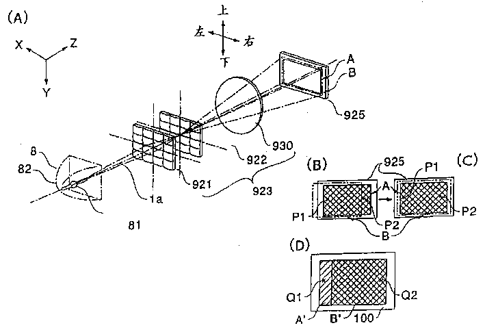
In this routine projection display device, as shown in Figure 5, the field of illumination of the liquid crystal light valve 925 of integrated optics system 923 can form the zone with respect to the image of liquid crystal light valve and carry out small adjustment up and down.
In Fig. 5 (A), the image that the field of illumination of liquid crystal light valve 925 of integrated optics system 923 and liquid crystal light valve 925 schematically are shown forms the relation of regional A.As describing, then because the view field of screen 100 generally is a rectangle, so correspondingly, the image of liquid crystal light valve 925 forms regional A and also constitutes rectangle with reference to this figure.The field of illumination B of integrated optics system 923 (zone of representing with thin dashed line among the figure) also becomes along the shape of this zone A.
As mentioned above, the image of liquid crystal light valve 925 forms the size setting of regional A according to the little circle of territory, area pellucida B.In other words, around the A of viewing area, be set with the back gauge of Rack.By setting back gauge, even, also always image can be formed regional A and be included in the B of field of illumination because of positioning error of opticses such as the 1st, the 2nd lens board 921,922 of integrated optics system 923 and overlapping lens 930 etc. changes the formation position of field of illumination B.
In this example, overlapping lens 930 shown in arrow among the figure, can utilize position adjusting mechanism up and down its installation site being finely tuned along the plane perpendicular to optical axis 1a.As position adjusting mechanism, for example, can consider to use flat spring on the light guide section 901,902 and position adjusting screw etc. about being configured in.
Installation site to overlapping lens 930 shown in Figure 6 is in an example of the mechanism that finely tunes up and down.Fig. 6 (A) be from the light path upstream side observe mechanism that the installation site of overlapping lens 930 is finely tuned figure, Fig. 6 (B) is that Fig. 6 (C) is the figure that observes this mechanism from the side from the figure of last light guide section 901 these mechanisms of unilateral observation.The lens installation site adjusting mechanism 700 of overlapping lens 930 is installed, has mode with screw-threaded coupling and be fixed on down infrabasal plate 710 on the light guide section 902.At the upper surface of this infrabasal plate 710, adjust substrate (pedestal adjustment plate) 720 to fix lens with the state of light path quadrature.This lens adjust substrate 720 have vertical wall 721, and middle body from its upper end to the horizontally extending upper wall 722 of upstream side (+Z direction) of light path.On vertical wall 721, lens with state support in parallel and vertically adjust plate (the 1st adjusts plate) 730.Vertically adjust the bottom of plate 730 at lens, be provided with the lower wall 731a, the 731b that extend to the light path upstream side,, the upper wall 732 that extends to the light path upstream side is being set in the upper end.Lens are vertically adjusted plate 730, and its lower wall 731a, 731b are bearing on the infrabasal plate 710 by calibrating spring 735, and upper wall 732 is pushed downwards by the adjustment screw 736 on the upper wall 722 that is installed in lens adjustment substrate 720.Therefore, by the amount of being screwed into of adjusting screw 736 is adjusted, can make lens vertically adjust plate 730 with respect to lens adjust substrate about in the of 720 (± Y direction) move.
In addition, when (± Y direction) adjusts the installation site of overlapping lens 930 about utilizing above-mentioned adjustment screw 736 edges, as be used to prevent lens vertically adjust plate 730 to the left and right (± directions X) mobile move anti-locking mechanism, adjust plate 730 upper edge Y directions at lens and be formed with a pair of groove 734, adjust on the substrate 720 at lens and forming a pair of protuberance 724 that inserts this groove respectively.
Vertically adjust on the plate 730 at lens, lens horizontal adjustment plate the 2nd with state support in parallel and adjust plate) 740.In addition, lens are vertically adjusted plate 730 and are also had pair of right and left sidewall 733a, the 733b that extends to the light path upstream side, and on the other hand, lens horizontal adjustment plate 740 has sidewall 743a, the 743b parallel with this sidewall 733a, 733b.And the sidewall 743a of lens horizontal adjustment plate 740 is pressed towards sidewall 743b one side by the calibrating spring 745 that is bearing on the sidewall 733a, and the sidewall 743b of another side is pressed to sidewall 743a one thruster by the adjustment screw 746 that is installed on the sidewall 733b.Therefore, by the amount of being screwed into of adjusting screw 746 is adjusted, can make lens horizontal adjustment plate 740 vertically adjust substrate about 730 (± directions X) and move with respect to lens.
In addition, when utilizing the installation site of the overlapping lens 930 of (± directions X) adjustment about above-mentioned adjustment screw 746 edges, as being used to prevent lens horizontal adjustment plate 740 (± Y direction) mobile mobile anti-locking mechanism up and down, the pair of holes 747 that forms at lens horizontal adjustment plate 740 upper edge directions Xs is vertically adjusted at lens and to be formed a pair of protuberance 737 that inserts this hole respectively on the substrate 730.
In the substantial middle part of lens horizontal adjustment plate 740, fixing overlapping lens 930.In this example, the part on the top of overlapping lens 930 is located by frame, and is fixing by the flat springs of fixing with screw 751 752 at 2 positions of bottom.As the lens of the inscape of this routine lens installation site adjusting mechanism 700 adjust substrate 720, lens vertically adjust plate 730, and each of 740 3 blocks of plates of lens horizontal adjustment plate on all be provided with and be used for the photoconduction that will penetrate from overlapping lens 930 peristome to look dissociated optical device.
Here, in this routine lens installation site adjusting mechanism 700, three blocks of plates, be that lens are adjusted substrate 720, lens and vertically adjusted plate 730, and lens horizontal adjustment plate 740, amount on the position at 4 positions that it is fixing to adjust plate fixing spring 755 with the U font at each 2 position up and down.Therefore, has the advantage that to adjust up and down the installation site of overlapping lens 930 lens installation site adjusting mechanism 700 being fixed under the state of following light guide section 902.In addition, adjust substrate 720, and the upper part of lens horizontal adjustment plate 740 at lens, be respectively equipped with cementing agent and accumulate portion 728,748, after the adjustment of the installation site of overlapping lens 930 finishes, cementing agent is flowed into this and accumulates portion from cementing agent filling orifice 904a, the 904b (with reference to Fig. 3) that is located on the light guide section 901, so that three plate bondings are fixing, thereby the changing of the relative positions takes place in the installation site that can prevent overlapping lens.
If can finely tune up and down the installation site of overlapping lens 930 by this way, then shown in Fig. 5 (B), when field of illumination B forms regional A when lateral excursion thereby the part that makes image form regional A can not get throwing light on respect to the image of liquid crystal light valve 925, can tighten or unscrew adjustment screw 746, finely tune about edge, installation site overlapping lens 930, the position that makes field of illumination B is along laterally moving, then shown in Fig. 5 (C), can adjust to and image is formed regional A be included in state in the B of field of illumination.And form regional A when above-below direction skew thereby the part that makes image form regional A can not get throwing light on respect to the image of liquid crystal light valve 925 as field of illumination B, can tighten or unscrew adjustment screw 736, the edge, installation site of overlapping lens 930 is finely tuned up and down, then same as described above, can adjust to and image is formed regional A be included in state in the B of field of illumination.
Here, about the fine setting of (± directions X), can carry out in the automatic or manual mode by the periphery illumination that projects to the projection image on the screen that is for example formed by liquid crystal light valve 925G is measured.That is, under state shown in Fig. 5 (B), field of illumination B is offset to the left, thereby the illumination that makes image on the liquid crystal light valve 925G form the right of regional A reduces.For the such skew to field of illumination B is adjusted, need only with the installation site of overlapping lens 930 to the left and right (± directions X) move up to make image form the left and right sides illumination P1 of regional A, the value that P2 reaches regulation gets final product.But, this method of adjustment, owing to must preestablish setting, so light source when the changing intractable little to light quantity.
Therefore,, then just there is no need to preestablish setting if the installation site move left and right of overlapping lens 930 is equated up to the left and right sides illumination P1, the P2 that make image form regional A, so even the little light source of light quantity also can easily handle by limited capacity after changing.In addition, the installation site move left and right of overlapping lens 930 is reached maximum up to the additive value that makes image form left and right sides illumination P1, the P2 of regional A, also there is no need to preestablish setting, so even also can be easy to processing after changing to the little light source of light quantity.
In addition, the fine setting of left and right directions (± directions X), the illumination that can replace the image on the liquid crystal light valve 925G being formed area peripheral edge portion is carried out method for measuring, and the periphery illumination of the projection image when seeing through under the state of liquid crystal light valve 925G its image projecting to screen 100 in illumination light is measured, and also can carry out in the automatic or manual mode.
As projecting under the state of Fig. 5 (B) on the screen 100, then shown in Fig. 5 (D), projection image B ' can not project to the left side of the original regional A ' that answers projection image.Therefore, the illumination of this left-hand component reduces.So, can measure left and right sides illumination Q1, the Q2 of the original regional A ' that answers projection image, and use with above-mentioned same quadrat method of finely tuning and finely tune by the illumination photometry on the liquid crystal light valve 925G.That is, the installation site move left and right of lens board 921 can be reached setting or the installation site move left and right of lens board 921 is equal to each other or the installation site move left and right of lens board 921 is reached maximum up to the additive value of illumination Q1, Q2 up to illumination Q1, Q2 up to illumination Q1, Q2.In addition, as mentioned above, if the installation site move left and right of lens board 921 additive value equal up to illumination Q1, Q2 or illumination Q1, Q2 is reached maximum, even then also can be easy to processing after changing to the little light source of light quantity.
Secondly, the fine setting of above-below direction (± Y direction) can be carried out in the automatic or manual mode by measuring the illumination up and down of the visual regional A of formation or the illumination up and down of projection image.When above-below direction is adjusted, with about adjust the same, the installation site of above-below direction that also can mobile lens plate 922, the illumination up to 2 positions reaches setting.And if the illumination of installation site up to 2 positions that moves up and down lens board 922 equates or the additive value of the illumination at 2 positions reaches maximum, even then also can be easy to processing after changing to the little light source of light quantity.
In addition, also can be without liquid crystal light valve 925G, and be benchmark with other liquid crystal light valve 925R, 925B, carry out the fine setting of the installation site of overlapping lens 930.
Like this owing to can finely tune to the installation site of overlapping lens 930, so, consider in advance do not need to resemble in the past the field of illumination skew and around the visual A of liquid crystal light valve the very wide back gauge of setting.Therefore and since should image form regional A around the back gauge that forms can be minimum, so can improve the utilization ratio of illumination light, and can improve the brightness of projection image.
In addition, even back gauge reduces, but by the installation site of overlapping lens 930 is finely tuned, the situation that the part that still can avoid the image of generation shown in Fig. 5 (B) to form regional A breaks away from field of illumination B.Therefore, the edge that also can not occur in projection image produces the disadvantage of shade etc.
In addition, in this routine projection display device 1000, final decision integrated optics system 923 the liquid-crystal apparatus field of illumination be the overlapping lens 930 that are configured in exiting side.In this example owing to can finely tune to above-mentioned overlapping lens 930, so can be simply and the field of illumination of adjusting liquid crystal light valve expeditiously form the position.Promptly, owing to make the optics (the 1st, the 2nd lens board 921,922) of the light path upstream side that is configured in overlapping lens 930 fixing and only the installation site of overlapping lens 930 is adjusted, so can under the state that the positioning error that will be configured in from the optics of the light path upstream side of overlapping lens 930 is included, adjust the formation position of field of illumination B, thereby can carry out simple and adjust operation efficiently.
In addition, in the present embodiment, can only adjust the installation site of overlapping lens 930 with the direction of optical axis 1a quadrature (± directions X, ± Y direction), if but could also adjust the installation site of optical axis 1a direction (± Z direction), then just could finely tune the size of the field of illumination that on liquid crystal light valve 925, forms.That is, after the installation site of overlapping lens 930 having been carried out adjust,, the size of field of illumination can be reduced to ultimate value by the fine setting on optical axis 1a direction with optical axis 1a orthogonal directions.Therefore, can make back gauge become minimum, thereby can further improve the utilization ratio of light.
In addition, also can accomplish to raise at any direction that intersects with optical axis 1a the installation site of the folded lens 930 of bulk wight.If can be like this raise the installation site of the folded lens 930 of bulk wight, then can also eliminate the deflection of the field of illumination B as shown in Figure 7 that will illustrate below, thereby can improve the homogeneity of throwing light at any direction that intersects with optical axis 1a.
As forming the main cause that skew takes place regional A with respect to the image of liquid crystal light valve 925, can also enumerate the reflecting surface setting angle of the catoptron on the light path that is configured in each color beam from the field of illumination B of the light of overlapping lens 930.The reflecting surface setting angle of catoptron is at 45 to optical axis, if the deflection shown in Fig. 7 (A), (B) will take place on the B of field of illumination this angle deviating, thereby shown in Fig. 5 (B), the part that image forms regional A breaks away from field of illumination B sometimes.In addition, because of left side illumination and the right side illumination of field of illumination B becomes inhomogeneous, so also just probably lost the advantage that adopts integrated optics system 923.Therefore, in this routine projection display device 1000, except that the fine setting of above-mentioned overlapping lens 930, can also make as shown in Figure 4 red beam R to the catoptron 943 of liquid crystal light valve 925R one lateral reflection, blue light beam B is rotated (direction of arrow of Fig. 4) to the reflecting surface angle of the catoptron 972 of liquid crystal light valve 925B one lateral reflection around the axis perpendicular to the plane that comprises incident light axis and reflection optical axis, finely tune with respect to incident light axis.As the setting angle adjusting mechanism of this catoptron, can consider to use flat spring the same and angular setting screw with the position adjusting mechanism of above-mentioned overlapping lens 930.
In Fig. 8 (A)~(C), an example of the mechanism that the setting angle of catoptron is finely tuned is shown.Fig. 8 (A) is the key diagram that is used to keep the holding plate 770 of catoptron 972, Fig. 8 (B) is the figure from the setting angle adjusting mechanism of last light guide section 901 unilateral observation catoptrons 972, and Fig. 8 (C) is the figure that observes the setting angle adjusting mechanism of catoptron 972 from the A-A section portion of Fig. 8 (A).Shown in above-mentioned each figure, angle-adjusting mechanism 760 has holding plate 770, utilizes the maintaining part 772a, the 772b that are provided with on this holding plate 770 keeping this catoptron 972 from the one side opposite with the reflecting surface of catoptron 972.In addition, the top of catoptron 972 is fixed on the holding plate 770 by clip 773.At the surperficial middle body of this holding plate 770, forming the axial region 771 that extends along the vertical direction.This axial region 771 is being supported by following light guide section 902 in rotating mode.Therefore, catoptron 972 can rotate the amount of regulation by holding plate 770 around the axis 1b of axial region 771.
In addition, on a lateral parts of holding plate 770 spring fixed seat 774 is being set, the 1st fulcrum 775a of calibrating spring 775 is embedded into this spring fixed seat 774.Arm 775d, the 775e of calibrating spring 775 contacts with the 777a of spring-loaded portion, 777b on being located at holding plate 770.On the other hand, the 2nd, the 3rd fulcrum 775b, the 775c of calibrating spring 775 contact with support 778 on being located at down light guide section 902.Therefore, can holding plate 770 be fixed with respect to following light guide section 902 by calibrating spring 775.
In addition, holding plate 770 is by the direction pushing that is located at down adjustment screw 776 arrow B in figure on the light guide section 902.Therefore, if an instrument is inserted from the screw operating portion 779 that is located at down on the light guide section 902, increase to adjust the amount of being screwed into of screw 776, then holding plate 770 because of its lateral parts be adjusted screw 776 to+B direction pushing in Fig. 8 (B) direction shown in the arrow R1 around the axis 1b of axial region 771 rotation.Therefore, can change the angle of the reflecting surface of catoptron 972, the incident angle of the light that incides catoptron 972 is increased.On the contrary, if reduce to adjust the amount of being screwed into of screw 776, then holding plate 770 rotates around the axis 1b of axial region 771 to-B direction tractive direction shown in the arrow R2 in Fig. 8 (B) because of its lateral parts is adjusted spring 775.Therefore, can change the angle of the reflecting surface of catoptron 972, the incident angle of the light that incides catoptron 972 is reduced.In other words, by the amount of being screwed into of adjusting screw 776 is adjusted, with the axis 1b perpendicular to the plane that comprises incident light axis and reflection optical axis is the center, adjusts the angle of the reflecting surface of catoptron 972, thereby can adjust the reflecting surface setting angle corresponding with incident light axis.
In addition, the mechanism as the reflecting surface angle of adjusting another catoptron 943 can certainly adopt mechanism same as described above.
In addition, in this example, after the setting angle to catoptron 943,972 has carried out fine setting, cementing agent is injected the cementing agent filling orifice 906a, 906b, 907a, the 907b (with reference to Fig. 3) that are located on the light guide section 901 be fixed.Although it is so fixing not necessarily necessary, but be effective to the changing of the relative positions of the catoptron 943,972 that prevents from reliably to cause because of external impact.
This fine setting, the periphery illumination that forms the zone by the image to liquid crystal light valve 925R or 925B carries out then deciding, and can carry out in the automatic or manual mode.Shown in Fig. 7 (A), (B), when deflection took place field of illumination B, left side illumination and the right side illumination of field of illumination B became inhomogeneous, thus about generation illumination deviation.Under state shown in Fig. 7 (A), the illumination P1 that image forms the regional A left side becomes bigger than the illumination P2 on the right, and under state shown in Fig. 7 (B), the illumination P2 that image forms regional A the right becomes greater than the illumination P1 on the left side.Therefore, identical with the fine setting of said lens plate, can rotate the setting angle of each catoptron 943,972, reach setting up to the left and right sides illumination P1, the P2 that make image form regional A.In addition, in order to adapt to the few light source of light quantity situation after changing, also can rotate the setting angle of each catoptron 943,972, equate, or the additive value that makes image form left and right sides illumination P1, the P2 of regional A reaches maximum up to the left and right sides illumination P1, the P2 that make image form regional A.
In addition, the fine setting of each catoptron 943,972, the same with the fine setting of overlapping lens 930, can replace the image on liquid crystal light valve 925R, the 925B is formed the mensuration of the illumination of area peripheral edge portion, and the periphery illumination of the projection image when seeing through under the state of liquid crystal light valve 925R, 925B its image projecting to screen 100 in illumination light is measured, and also can carry out in the automatic or manual mode.Promptly, as under Fig. 7 (A) or state (B), projecting on the screen 100, then even because of the left and right sides uneven illumination of projection image, so, the same in the time of also can forming the illumination photometry of regional A with image, measure the left and right sides illumination of projection image, and rotate the setting angle of each catoptron 943,972, the illumination about making be equal to each other or make about the additive value of illumination reach maximum.
When finely tuning, can rotate catoptron 943,972 simultaneously, but also can adopt the method that setting angle is finely tuned successively, promptly, at first projection image or the image formation zone with liquid crystal light valve 925R is that benchmark rotates catoptron 943, carrying out angular setting, and then to form the zone with the projection image of liquid crystal light valve 925B or image be that benchmark rotates catoptron 972, to carry out angular setting.
In addition, in this example, can finely tune the catoptron 943 of the most close liquid crystal light valve 925R, 925B and 972 setting angle, but can also be further be that part or all setting angle of bluish-green reflecting dichroic mirror 941, green reflecting dichroic mirror 942, light incident side catoptron 971 is finely tuned to other optical parameters, also can replace catoptron 943 and 972, and part or all setting angle of above-mentioned other optical parameters is finely tuned.But, resembling this example like this, can finely tune being configured in, structurally or to adjust on the precision be best in the position with the setting angle of the hithermost locational catoptron 943 of liquid crystal light valve 925R, 925B and 972.
In addition, also can replace catoptron 972 and the setting angle of middle lens 973 is adjusted, after having carried out this adjustment, same effect in the time of can having obtained and adjust the setting angle of catoptron 972.
Like this owing to can finely tune to the setting angle of catoptron 943 and 972, so, consider in advance do not need to resemble in the past the field of illumination skew and the image of liquid crystal light valve form regional A around the very wide back gauge of setting.Therefore and since should image form regional A around the back gauge that forms can be minimum, so can improve the utilization ratio of illumination light, and can improve the brightness of projection image.
In addition, even back gauge reduces, but by the setting angle of catoptron 943 and 972 is finely tuned, the situation that the part that still can avoid the image of generation shown in Fig. 7 (A), (B) to form regional A breaks away from field of illumination B.Therefore, also can not occur in the disadvantages such as edge generation shade of projection image.
In addition, because by catoptron 943 and 972 is finely tuned the deflection that can eliminate field of illumination B, so can make full use of the advantage that can evenly throw light on of integrated optics system 923 to greatest extent, and can obtain brightness projection image very uniformly.
The angle-adjusting mechanism of optical parameters such as aforesaid catoptron also is effective in the projection display device that does not adopt integrated optics system 923.
(another example 1)
Below, an example of the projection display device of having used another structure of the present invention is described.The optical system of this routine projection display device 2000 has one and has integrated optics system and the special spectroscopical polarized light illumination device of light beam of polarized light of shape.In addition, in this example, the structure for identical with above-mentioned projection display device 1000 is marked with the identical reference marks that adopted with Fig. 1~Fig. 8, and its detailed description is omitted.
Fig. 9 is the simple structural drawing of the optical system major part of this routine projection display device 2000 of expression, the structure on the plane of XZ shown in the figure.This routine projection display device 2000, roughly by polarized light illumination device 1, with white light beam be separated into 3 looks the look tripping device that coloured light is arranged, according to display message to 3 transmission-type liquid crystal devices coloured light is respectively arranged modulating and form displayed image, with coloured light compositing of 3 looks and form color image the look synthesizer, and the projection optical system that this color image carries out Projection Display constituted.
Polarized light illumination device 1 has the light source portion 10 that light beam of polarized light is at random penetrated to a direction, and it is one type light beam of polarized light basically that the light beam of polarized light at random that penetrates from this light source portion 10 is transformed to by polarisation converting means 20.
Light source portion 10 roughly by illuminator 101, and parabolic mirror 102 constitute, reflect to a direction by parabolic mirror 102 from the light of illuminator 101 emission, the light beam of formation almost parallel incides the polarisation converting means.Here, the configuration mode of light source portion 10 is to make the light source optical axis R of light source portion 10 be in the state behind directions X parallel displacement certain distance D with respect to systematic optical axis L.
Secondly, polarisation converting means 20 by the 1st optical parameter 200, and the 2nd optical parameter 300 constitute.
The 1st optical parameter 200 is equivalent to the 1st lens board 921 of above-mentioned projection display device 1000, constitutes by arranging by matrix form at the rectangular a plurality of beam separation lens 201 of the section on XY plane.Light source optical axis R is configured to make it to pass through the center of the 1st optical parameter 200.Incide the light of the 1st optical parameter 200, be separated into separated a plurality of intermediate beam 202 by beam separation lens 201 in the space, by means of the optically focused effect of beam separation lens 201, intermediate beam 202 (the XY plane among Fig. 9) in the plane vertical with systematic optical axis L is formed and beam separation lens 201 the same number of optically focused images on the position of assembling simultaneously.In addition, the section configuration of beam separation lens 2011 on the XY plane is set at the shape formation similar figures that form the zone with the image of liquid crystal light valve.In this example, because of the supposition field of illumination is the rectangle of the directions X length on the XY plane, so the section configuration of beam separation lens 201 on the XY plane also is rectangle.
The 2nd optical parameter 300 be roughly by condenser lens array 310, polarisation separative element array 320, select polarizer 380 and as the assembly that the overlapping lens 390 of overlapping device constitute, be configured near the plane vertical with systematic optical axis L the position near the formation optically focused image of the 1st optical parameter 200 (the XY plane among Fig. 9).In addition, when the light beam that incides the 1st optical parameter 200 has very good collimation, also condenser lens array 310 can be saved from the 2nd optical parameter.Here, as the condenser lens array 310 and the 1st optical parameter 200 of the inscape of the 2nd optical parameter 300, be equivalent to the integrated optics system of above-mentioned projection display device 1000.The 2nd optical parameter 300, it is consistent with the polarization direction of another light beam of polarized light and with the mechanism of the field of illumination at each position of beam direction behind the polarization direction basically identical to have a polarization direction that makes a light beam of polarized light after each intermediate beam 202 spatially being separated into P light beam of polarized light and S light beam of polarized light.
Condenser lens array 310 is structurally basic identical with the 1st optical parameter 200.Promptly, condenser lens array 310 will press matrix form with the beam separation lens 201 the same number of collector lenses 311 that constitute the 1st optical parameter 200 and arrange, and have the function that the privileged site that simultaneously each intermediate beam 202 is focused at polarisation separative element array 320 simultaneously leads.Therefore, preferably according to the characteristic of the intermediate beam 202 that forms by the 1st optical parameter 200 and consider that desirable state is the chief ray vergence direction and the parallel this point of systematic optical axis L that incides the light of polarisation separative element array 320, make the characteristic of each collector lens distinguish optimization.But, in general, consider the cost degradation of optical system and be easy to design, also can adopt with the 1st optical parameter 200 identical optical parameters as condenser lens array 310, perhaps, so employing in the case of this example, adopts the 1st optical parameter 200 as condenser lens array 310 with the condenser lens array that the collector lens that becomes similar figures with the shape of beam separation lens 201 on the XY plane becomes.In addition, also condenser lens array 310 can be configured in the position (near the 1st optical parameter 200 1 sides) of leaving polarisation separative element array 320.
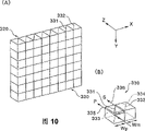
Polarisation separative element array 320 shown in Figure 10 (A), (B), constitutes a plurality of polarisation separative elements 330 is pressed the matrix form structure arranged.The aligning method of polarisation separative element 330, because of the constituted mode of the 1st optical parameter 200 is to adopt the concentric serial beam separation lens 201 of the lens peculiarity with the beam separation lens 201 that constitute the 1st optical parameter 200 and each beam separation lens 201 is arranged by the orthogonal matrix form, so polarisation separative element array 320 also is by identical polarisation separative element 330 is constituted by the arrangement of orthogonal matrix form on identical direction.In addition, when the same row polarisation separative element of arranging in the Y direction is identical polarisation separative element, the method that employing polarisation separative element that the Y direction is elongated is arranged the polarisation separative element array 320 that the back constitutes along directions X, can reduce on the interface between the polarisation separative element light loss, can to lower simultaneously aspect the manufacturing cost of polarisation separative element array be favourable.
Polarisation separative element 330 is the cubic cylindricality structures that have a pair of polarisation parting plane 331 and reflecting surface 332 in inside, has the effect that each intermediate beam that will incide the polarisation separative element spatially is separated into P light beam of polarized light and S light beam of polarized light.Polarisation separative element 330 becomes similar figures in the section configuration on the XY plane with the section configuration of beam separation lens 201 on the XY plane, that is, be laterally long rectangle.Therefore, with horizontal (directions X) alignment arrangements of polarisation parting plane 331 and reflecting surface 332 edges.Here, the configuration mode of polarisation parting plane 331 and reflecting surface 332 is, polarisation parting plane 331 becomes the inclination angle of 45 degree approximately with respect to systematic optical axis L, and reflecting surface 332 constitutes the state parallel with polarisation parting plane 331, in addition, polarisation parting plane 331 is equated with the projected area (equaling the area of hereinafter described S exit facet 334) of reflecting surface 332 on the XY plane in the projected area on the XY plane (equaling the area of hereinafter described P exit facet 333).Therefore, in this example, exist the zone to exist the transverse width Wm of zone on the XY plane to set equally polarisation parting plane 331 at transverse width Wp on the XY plane and reflecting surface 332.In addition, general, polarisation parting plane 331 can form by the electricity consumption dielectric multilayer-film, and reflecting surface 332 electricity consumption dielectric multilayer-films or aluminium film form.
Incide the light of polarisation separative element 330, on polarisation parting plane 331, be separated into and do not change direct of travel and P light beam of polarized light 335 by polarisation parting plane 331 and be the S light beam of polarized light 336 of the direction of directive reflecting surface 332 by polarisation parting plane 331 reflection back going direction changings.P light beam of polarized light 335 directly penetrates from polarisation separative element 330 through P exit facet 333, and 336 of S light beam of polarized light change direct of travels by reflecting surface 332, becomes the state substantially parallel with P light beam of polarized light 335, and penetrates from polarisation separative element 330 through S exit facet 334.Therefore, incide the light beam of polarized light at random of polarisation separative element 330, be separated into the different P light beam of polarized light 335 of polarization direction and 336 two kinds of light beam of polarized light of S light beam of polarized light by polarisation separative element 330, and penetrate to essentially identical direction from the different parts (P exit facet 333 and S exit facet 334) of polarisation separative element 330.Because polarisation separative element 330 has aforesaid effect, the existence zone of the polarisation parting plane 331 of each polarisation separative element 330 so each intermediate beam 202 must be led, for this reason, should set each polarisation separative element 330 and the position relation of each collector lens 311 and the lens peculiarity of each collector lens 311, so that make intermediate beam 202 incide the central portion of the polarisation parting plane 331 in each polarisation separative element.Especially, in the case of this example, for the central shaft arrangement of each collector lens 311 is become to make its central portion that passes through the polarisation parting plane 331 in each polarisation separative element, condenser lens array 310 should be configured in and on directions X, the stagger state of 1/4 the distance that is equivalent to polarisation separative element 330 transverse width W of polarisation separative element array 320.
Describe according to Fig. 9 once more.
Exit facet one side at polarisation separative element array 320 is being provided with the selection polarizer 380 that λ/2 polarizers are disposed regularly.That is,, do not dispose λ/2 polarizers in the part of S exit facet 334 only at part configuration λ/2 polarizers of the P exit facet 333 of the polarisation separative element 330 that constitutes polarisation separative element array 320.According to the configuration status of this λ/2 polarizers, the P light beam of polarized light that penetrates from polarisation separative element 330, the turning effort that is subjected to polarization direction when by λ/2 polarizers is transformed to the S light beam of polarized light.On the other hand, because the S light beam of polarized light that penetrates from S exit facet 334 does not pass through λ/2 polarizers,, still pass through to select polarizer 380 with former S light beam of polarized light so polarization direction does not change.In sum, by means of polarisation separative element array 320 and selection polarizer 380, the random intermediate beam 202 of polarization direction can be transformed to one type light beam of polarized light (being the S light beam of polarized light in this case).
Selecting exit facet one side of polarizer 380, i.e. exit facet one side of the 2nd optical parameter 300, disposing overlapping lens 390, by selecting polarizer 380 packs to become light beam behind the S light beam of polarized light, and overlap on the field of illumination by the field of illumination of overlapping lens 390 each liquid-crystal apparatus of guiding.Here, overlapping lens 390 are 1 phacoid not necessarily, can be assemblys of a plurality of lens as the 2nd lens board 922 of the 1st optical parameter 200 or above-mentioned projection display device 1000 also.
As conclude the function of the 2nd optical parameter 300, then will overlap on the field of illumination by the 2nd optical parameter 300 by the intermediate beam 202 (that is the picture plane that cuts out by beam separation lens 201) that the 1st optical parameter 200 is cut apart exactly.Meanwhile, to at random by the polarisation separative element array 320 that is positioned at the centre, light beam of polarized light is that intermediate beam 202 spatially is separated into two kinds of different light beam of polarized light of polarization direction, when by selection polarizer 380, be transformed to one type light beam of polarized light basically.Therefore, the image of liquid crystal light valve form the zone can roughly throw light on uniformly by one type light beam of polarized light basically.
As mentioned above, as according to this routine polarized light illumination device 1, polarisation converting means 20 then by constituting by the 1st optical parameter 200 and the 2nd optical parameter 300, to be transformed to one type light beam of polarized light from the light beam of polarized light at random that light source portion 10 penetrates basically, simultaneously, have and to form the effect of evenly throwing light in the zone by the light beam after this polarization direction unanimity to the image of liquid crystal light valve.In addition, owing in the production process of light beam of polarized light, there is not light loss basically,, therefore, has the high feature of utilization ratio of light so the image of the liquid crystal light valve that the most light that penetrates from light source portion 10 all can be led forms the zone.
In addition, in this example, constitute condenser lens array 310, polarisation separative element array 320, the selection phase-plate 380 of the 2nd smooth key element 300, optically by integration, thereby can reduce the light loss that on the interface of these parts, produces, bringing into play the effect that the light utilization ratio is further improved.
In addition, for cooperating laterally long rectangle diagram pictograph to become the shape in zone, make the beam separation lens 201 that constitute the 1st optical parameter 200 be horizontal long rectangle, adopt the form that to separate at horizontal (directions X) from two kinds of light beam of polarized light that polarisation separative element array 320 penetrates simultaneously.Therefore, even when becoming the zone to throw light on, can not waste light quantity yet, thereby can improve illumination efficiency (light utilization ratio) laterally long rectangle diagram pictograph.
Generally when the random light beam of polarization direction is separated into P light beam of polarized light and S light beam of polarized light simply, the light beam overall width after the separation will expand 2 times to, and therewith correspondingly, optical system also will maximize.But, in polarized light illumination device 1 of the present invention, form a plurality of small optically focused images by the 1st optical parameter 200, make full use of the space that does not have light that in the forming process of these optically focused images, produces, and be configured in this space by the reflecting surface 32 with polarisation separative element 330, absorb because of being separated into the width of light beam expansion in the horizontal that 2 light beam of polarized light produce, so, overall width with light beam can not enlarge, thereby has the feature that can realize the compact optical system.
In the projection display device 2000 that has adopted this polarized light illumination device 1, using the liquid-crystal apparatus of the pattern that a kind of light beam of polarized light is modulated.Therefore, as adopt existing lighting device to incite somebody to action light beam of polarized light guiding liquid-crystal apparatus at random, then the only about half of light in the light beam of polarized light is absorbed by the Polarizer (not shown) and has become heat at random, so, the utilization ratio of light worsens, and exists the essential problem that adopts the large-scale strong noise cooling device that suppresses the Polarizer heating simultaneously.Yet in this routine projection display device 2000, the problems referred to above are significantly improved.
Promptly, in this routine projection display device 2000, in polarized light illumination device 1, only a kind of light beam of polarized light, for example P light beam of polarized light are applied the turning effort of plane of polarisation, and another kind of light beam of polarized light, for example S light beam of polarized light are kept and the polarization direction consistent state with λ/2 polarizers.Therefore, with liquid crystal light valve 925R, 925G, the 925B that one type light beam of polarized light guiding is positioned at 3 positions that be essentially that makes after the polarization direction unanimity, so the light that is absorbed by Polarizer is considerably less, therefore, the utilization ratio of light improves, and can obtain bright projection image.
In addition, in polarized light illumination device 1, in the 2nd optical parameter 300, two kinds of light beam of polarized light are spatially separated along horizontal (directions X).Therefore, can not waste light quantity, and can be suitable for laterally long rectangular liquid-crystal apparatus is thrown light on.
In addition, in this routine polarized light illumination device 1 inside,, in polarisation separative element array 320, suppressing the expansion of the width of emergent light though polarisation transform optics key element is housed.This situation means the light that does not almost have with wide-angle incident liquid-crystal apparatus when the illumination liquid-crystal apparatus.Therefore, even do not adopt the great projecting lens of the little bore of F value also can realize the projection image that becomes clear, consequently, can realize small-sized projection display device.
Have again, in this routine projection display device 2000 that constitutes by this way, also the same with above-mentioned projection display device 1000, if can to the installation site of the overlapping lens 390 of exit facet one side that is configured in this polarized light illumination device 1 with the direction of optical axis L quadrature on adjust, then can all around finely tune, be positioned at the field of illumination so always can make the image of each liquid-crystal apparatus form the zone to each liquid crystal light valve 925R, 925G of polarized light illumination device 1, the edge, field of illumination of 925B.
In addition, the mechanism as the installation site of adjusting overlapping lens 390 can adopt the lens installation site adjusting mechanism that illustrated with reference to Fig. 6.In addition, the method for trimming of installation site and the resulting action effect of adjustment by the field of illumination etc. are identical with the situation of above-mentioned projection display device 1000.
As mentioned above, in this routine projection display device 2000, owing to can finely tune to the installation site of overlapping lens 390, so, consider in advance do not need to resemble in the past the field of illumination skew and the image of liquid-crystal apparatus form the zone around the very wide back gauge of setting.Therefore, can be minimum owing to should form the regional back gauge that forms on every side at image, thus can improve the utilization ratio of illumination light, and can improve the brightness of projection image.
In addition, even back gauge reduces, but finely tune by the installation site to above-mentioned each optical element, the part image that still can avoid liquid-crystal apparatus takes place forms the situation that the zone breaks away from the field of illumination of polarized light illumination device.Therefore, the edge that also can not occur in projection image forms the disadvantage of shade etc.
In addition, the optical element of the liquid-crystal apparatus field of illumination of polarized light illumination device 1 in final decision, is intermediate beam is overlapped overlapping lens 390 on the field of illumination.In this example, owing to can finely tune to the installation site of these overlapping lens 390, so can be configured in overlapping lens 390 the light path upstream side optic stationary and only the installation site of overlapping lens 390 is adjusted, thereby can will be configured in the formation position of adjusting field of illumination B under the state that the positioning error of the 1st optical parameter 200 opticses such as grade of light path upstream side included from overlapping lens 390, therefore, the field of illumination that can adjust liquid crystal light valve expeditiously forms the position, and it is also without difficulty to adjust operation.
Here, in this routine projection display device 2000, form the main cause of zone skew as the liquid-crystal apparatus field of illumination of polarized light illumination device 1 with respect to the image of this liquid-crystal apparatus, also can enumerate the reflecting surface setting angle error of the catoptron on the light path that is configured in each color beam.The reflecting surface setting angle of catoptron is at 45 to optical axis, if the deflection shown in Fig. 7 (A), (B) then will take place on the field of illumination this angle deviating, therefore, the image that the field of illumination will exceed liquid-crystal apparatus forms regional scope.And when deflection takes place in the field of illumination, because of left side illumination and the right side illumination of field of illumination becomes inhomogeneous, so also just probably lost the advantage of employing polarized light illumination device 1.
Therefore, in this routine projection display device 2000, also can make the reflecting surface angle of the catoptron 943,972 on the light path that is configured in each color beam rotate (direction of arrow of Fig. 9), finely tune with respect to incident light axis around axis perpendicular to the plane that comprises incident light axis and reflection optical axis.Can also adjust up and down the installation site that is configured in the intermediate lens 973 between the catoptron 943,972.And, the angle-adjusting mechanism that illustrated with reference to Fig. 8 being arranged as an example of the mechanism of the reflecting surface setting angle of adjusting each catoptron, the example as the mechanism of the installation site of adjusting intermediate lens 973 has the installation site adjusting mechanism that illustrated with reference to Fig. 6.
(another example 2)
In 2 examples that illustrated in front, as liquid crystal light valve 925R, 925G, 925B, adopting the liquid crystal light valve of transmission-type, even but adopted in the projection display device of reflective liquid crystal device replacing this class liquid crystal light valve, the present invention can be suitable for equally.At this, the transmissive liquid crystal light valve that replaces above-mentioned projection display device 2000 has been described and an example that has adopted the projection display device of reflection-type light valve.In this routine projection display equipment 3000, for the structure identical with above-mentioned projection display device 2000, be marked with Fig. 9, Figure 10 in the identical reference marks that adopted, its detailed description is omitted.
Figure 11 is a simple structural drawing of overlooking the major part of observing this routine projection display equipment 3000.This Figure 11 is the sectional view by the XZ plane at the center of the 2nd optical parameter 300.
Light beam of polarized light spectroscope 400 is by having the S light beam of polarized light to roughly becoming 45 ° direction reflection with the XY plane of Figure 11 and the prism of the S light beam of polarized light reflecting surface 401 that the P light beam of polarized light sees through being constituted.From the light beam that the 2nd optical parameter 300 penetrates, be the light beam that is transformed to a kind of polarization direction basically, so almost be that whole light beams is reflected or transmissions by light beam of polarized light spectroscope 400.In this example, the light beam that penetrates from the 2nd optical parameter 300 is the S light beam of polarized light, this S light beam of polarized light incides the prism unit 500 of having pasted dichroic coating by the X font by behind 90 ° of S light beam of polarized light reflecting surface 401 warpages, is separated into 3 kinds of color components of R, G, B here.The light of each color component after the separation incides along reflective liquid crystal device 600R, 600G, the 600B of 3 limit configurations of prism unit 500.Incide the light beam of reflective liquid crystal device 600R, 600G, 600B, modulate by reflective liquid crystal device 600R, 600G, 600B.
In Figure 12, the example of reflective liquid crystal device 600R, 600G, 600B is shown.Reflective liquid crystal device 600R, 600G, 600B are that the TFT on-off element is connected in active array type liquid-crystal apparatus by each pixel of matrix form configuration, have liquid crystal layer 620 is clipped in structure between a pair of substrate 610,630.Substrate 610 is made of silicon, on its part formation source 611, leak 616.In addition, the raceway groove that also forms the source electrode 612 that is made of aluminium lamination and drain electrode 617 on substrate 610, be made of silicon dioxide layer 613, the gate electrode that is made of silicon layer 614 and tantalum layer 615, and the reflection pixel capacitors 619 that is made of interlayer dielectric 618 and aluminium lamination, drain electrode 617 and reflection pixel capacitors 619 are electrically connected by contact hole H.Because of reflection pixel capacitors 619 is opaque, so can be layered on gate electrode, source electrode 612, the drain electrode 617 across interlayer dielectric 618.It is quite little that distance X between the pixel capacitors 619 of adjacency can be made, so that the aperture ratio can be got is bigger, thereby the brightness that can improve projection image.In addition, in this example, be provided with by leak 616, silicon dioxide layer 613 ', silicon layer 614 ', the maintenance electric capacity of tantalum layer 615 ' constitute.
On the other hand, the substrate 630 that subtend is provided with by forming the opposite electrode 631 that is made of ITO on the face of liquid crystal layer 620 1 sides, is forming on another side and is preventing reflection horizon 632.In this example, as liquid crystal layer 620, adopt when not applying voltage (OFF) liquid crystal molecule 621 vertical orientated, when applying voltage (ON) liquid crystal molecule 621 by the liquid crystal layer that reverses 90 ° super isotropic orientation.Therefore, as shown in figure 11, when not applying voltage (OFF), incide the S light beam of polarized light of reflective liquid crystal device 600R, 600G, 600B from light beam of polarized light spectroscope 400, do not change its polarization direction ground and return light beam of polarized light spectroscope 400, so by not arriving projecting lens unit 6 after 400 reflections of light beam of polarized light spectroscope from reflective liquid crystal device 600R, 600G, 600B.And when applying voltage (ON), incide the S light beam of polarized light of reflective liquid crystal device 600R, 600G, 600B from light beam of polarized light spectroscope 400, owing to reversing of liquid crystal molecule 621 changes its polarization direction, become the P light beam of polarized light, after seeing through S light beam of polarized light spectroscope 400, project on the screen 100 by projecting lens unit 6.
Describe according to Figure 11 once more.Light beam by after reflective liquid crystal device 600R, 600G, the 600B modulation is synthesized by prism unit 500, and projects on the screen 100 by light beam of polarized light spectroscope 400, projecting lens unit 6.
In this routine projection display device 3000, owing to also the installation site of overlapping lens 390 that is configured in the 2nd optical parameter 300 exit facets one side of the polarisation converting means 20 that constitutes polarized light illumination device 1 can be moved up and down in the direction with light shaft positive cross, so suitable position and shape can be adjusted in the liquid-crystal apparatus field of illumination of this polarized light illumination device 1.In addition, the adjusting mechanism of these adjustable positions, method of adjustment, by adjusting resulting action effect are identical with the situation of above-mentioned projection display device 2000.
In addition, this routine projection display device 3000 except that the adjustment of field of illumination, after obtaining the effect identical with above-mentioned 2 kinds of projection display devices, can also be obtained following effect.That is, because look tripping device and look synthesizer be made of same prism unit, so can make optical path length very short.In addition, because of the aperture of liquid-crystal apparatus bigger than also, so can prevent the loss of light to greatest extent.Therefore, even do not adopt bigbore projecting lens can obtain very bright projection image yet.In addition, by adopting more plain, the 2nd optical parameter of the 1st optics, can obtain on illumination also uniformly light beam of polarized light as illumination light, so can on whole display surface and projected picture, obtain very evenly and very bright projection image with uniform brightness.
In addition, as the modulating device of reflection-type, enumerate reflective liquid crystal device 600R, 600G, 600B in this example, but can certainly use the modulating device beyond the liquid-crystal apparatus, the pattern of the material of its structure, its each inscape and liquid crystal layer 620 also is not limited to above-mentioned example.
Have again, adopt whole prism to constitute with the prism 501 that constitutes prism unit 500, then can prevent in its borderline light loss, thereby can further improve the utilization ratio of light if will constitute the prism 402 of light beam of polarized light spectroscope 400.
(another example 3)
In above-described 3 examples, the micro-adjusting mechanism of optical parameter of the projection display device of projectable's color image display has been described, but this micro-adjusting mechanism is suitable for too to the projection display equipment of the pattern of projection soot-and-whitewash.
In addition,, also be not limited to above-mentioned example,, also can not lose effect of the present invention even these configurations are changed about the configuration of optical system.
In addition, as projection display device, except illustrated in this example from the front projection type display device of the sightingpiston lateral projection image of screen, also have back projection type display device from lateral projection's image opposite with the sightingpiston side of screen.The present invention also can be applicable to this back projection type display device certainly.
As mentioned above, in projection display device of the present invention, finely tune the installation site that structurally can form the overlapping device in zone to the image that a plurality of intermediate beam is overlapped modulating device.Meanwhile, when configuration reflection unit on the light path from the light source to the modulating device, can finely tune the setting angle of this reflection unit.Therefore, finely tune owing to can form the position to the field of illumination of the illumination light of the modulating device that is used to throw light on, so, always the formation set positions of field of illumination can be formed regional position to the image that comprises modulating device.
Therefore, need not form after the situation in zone at the image that modulating device is departed from the imagination field of illumination and image form the zone around form big back gauge.Therefore, the utilization ratio of illumination light can be improved, and the brightness of projection image can be improved.In addition, comprise the position that image forms the zone, so also can not occur in the disadvantage that the projection image edge produces shade etc. owing to the field of illumination of illumination light can be formed on.
In addition, in the present invention, the optics that can the modulating device lighting position to final decision is that finely tune the installation site of overlapping device, so can adjust the formation position of field of illumination under the state that the alignment error of the optics (optical element) that will be configured in overlapping device preceding-stage side (upstream side of light path) etc. etc. is included.The field of illumination of therefore, can be simply and adjusting modulating device expeditiously forms the position.