CN112993473A - Battery, battery module, battery pack and electric vehicle - Google Patents
Battery, battery module, battery pack and electric vehicle Download PDFInfo
- Publication number
- CN112993473A CN112993473A CN201911199558.6A CN201911199558A CN112993473A CN 112993473 A CN112993473 A CN 112993473A CN 201911199558 A CN201911199558 A CN 201911199558A CN 112993473 A CN112993473 A CN 112993473A
- Authority
- CN
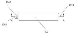
- China
- Prior art keywords
- electrode
- battery
- current lead
- polymer film
- out portion
- Prior art date
- Legal status (The legal status is an assumption and is not a legal conclusion. Google has not performed a legal analysis and makes no representation as to the accuracy of the status listed.)
- Granted
Links
Images




Classifications
-
- B—PERFORMING OPERATIONS; TRANSPORTING
- B60—VEHICLES IN GENERAL
- B60L—PROPULSION OF ELECTRICALLY-PROPELLED VEHICLES; SUPPLYING ELECTRIC POWER FOR AUXILIARY EQUIPMENT OF ELECTRICALLY-PROPELLED VEHICLES; ELECTRODYNAMIC BRAKE SYSTEMS FOR VEHICLES IN GENERAL; MAGNETIC SUSPENSION OR LEVITATION FOR VEHICLES; MONITORING OPERATING VARIABLES OF ELECTRICALLY-PROPELLED VEHICLES; ELECTRIC SAFETY DEVICES FOR ELECTRICALLY-PROPELLED VEHICLES
- B60L53/00—Methods of charging batteries, specially adapted for electric vehicles; Charging stations or on-board charging equipment therefor; Exchange of energy storage elements in electric vehicles
- B60L53/50—Charging stations characterised by energy-storage or power-generation means
- B60L53/53—Batteries
-
- Y—GENERAL TAGGING OF NEW TECHNOLOGICAL DEVELOPMENTS; GENERAL TAGGING OF CROSS-SECTIONAL TECHNOLOGIES SPANNING OVER SEVERAL SECTIONS OF THE IPC; TECHNICAL SUBJECTS COVERED BY FORMER USPC CROSS-REFERENCE ART COLLECTIONS [XRACs] AND DIGESTS
- Y02—TECHNOLOGIES OR APPLICATIONS FOR MITIGATION OR ADAPTATION AGAINST CLIMATE CHANGE
- Y02E—REDUCTION OF GREENHOUSE GAS [GHG] EMISSIONS, RELATED TO ENERGY GENERATION, TRANSMISSION OR DISTRIBUTION
- Y02E60/00—Enabling technologies; Technologies with a potential or indirect contribution to GHG emissions mitigation
- Y02E60/10—Energy storage using batteries
-
- Y—GENERAL TAGGING OF NEW TECHNOLOGICAL DEVELOPMENTS; GENERAL TAGGING OF CROSS-SECTIONAL TECHNOLOGIES SPANNING OVER SEVERAL SECTIONS OF THE IPC; TECHNICAL SUBJECTS COVERED BY FORMER USPC CROSS-REFERENCE ART COLLECTIONS [XRACs] AND DIGESTS
- Y02—TECHNOLOGIES OR APPLICATIONS FOR MITIGATION OR ADAPTATION AGAINST CLIMATE CHANGE
- Y02T—CLIMATE CHANGE MITIGATION TECHNOLOGIES RELATED TO TRANSPORTATION
- Y02T10/00—Road transport of goods or passengers
- Y02T10/60—Other road transportation technologies with climate change mitigation effect
- Y02T10/70—Energy storage systems for electromobility, e.g. batteries
-
- Y—GENERAL TAGGING OF NEW TECHNOLOGICAL DEVELOPMENTS; GENERAL TAGGING OF CROSS-SECTIONAL TECHNOLOGIES SPANNING OVER SEVERAL SECTIONS OF THE IPC; TECHNICAL SUBJECTS COVERED BY FORMER USPC CROSS-REFERENCE ART COLLECTIONS [XRACs] AND DIGESTS
- Y02—TECHNOLOGIES OR APPLICATIONS FOR MITIGATION OR ADAPTATION AGAINST CLIMATE CHANGE
- Y02T—CLIMATE CHANGE MITIGATION TECHNOLOGIES RELATED TO TRANSPORTATION
- Y02T10/00—Road transport of goods or passengers
- Y02T10/60—Other road transportation technologies with climate change mitigation effect
- Y02T10/7072—Electromobility specific charging systems or methods for batteries, ultracapacitors, supercapacitors or double-layer capacitors
-
- Y—GENERAL TAGGING OF NEW TECHNOLOGICAL DEVELOPMENTS; GENERAL TAGGING OF CROSS-SECTIONAL TECHNOLOGIES SPANNING OVER SEVERAL SECTIONS OF THE IPC; TECHNICAL SUBJECTS COVERED BY FORMER USPC CROSS-REFERENCE ART COLLECTIONS [XRACs] AND DIGESTS
- Y02—TECHNOLOGIES OR APPLICATIONS FOR MITIGATION OR ADAPTATION AGAINST CLIMATE CHANGE
- Y02T—CLIMATE CHANGE MITIGATION TECHNOLOGIES RELATED TO TRANSPORTATION
- Y02T90/00—Enabling technologies or technologies with a potential or indirect contribution to GHG emissions mitigation
- Y02T90/10—Technologies relating to charging of electric vehicles
- Y02T90/12—Electric charging stations
Landscapes
- Engineering & Computer Science (AREA)
- Power Engineering (AREA)
- Transportation (AREA)
- Mechanical Engineering (AREA)
- Sealing Battery Cases Or Jackets (AREA)
- Connection Of Batteries Or Terminals (AREA)
Abstract
The application provides a battery, a battery module and a battery pack. The battery comprises a shell, wherein a containing cavity is defined in the shell, and a plurality of electric core assemblies are arranged in the containing cavity; each electric core component comprises a polymer film bag, a pole core encapsulated in the polymer film bag, and a first electrode and a second electrode which are electrically connected with the pole core and extend out of the polymer film bag to be externally used for leading out current; the electric core components are connected in series, and the first electrode of one electric core component in the two electric core components connected in series is inserted into the second electrode of the other electric core component. The battery provided by the application has the advantages of high battery capacity, few assembly processes, small internal resistance and more stable battery performance.
Description
Technical Field
The invention belongs to the field of batteries, and particularly relates to a battery, a battery module, a battery pack and an electric vehicle.
Background
With the continuous popularization of new energy vehicles, the use requirements of power batteries in the new energy vehicles become higher and higher. Particularly, the mileage requirement of a user on the new energy vehicle during the continuous process is continuously improved, and the total capacity of a battery pack used by the new energy vehicle is continuously improved; meanwhile, when the power battery pack is used, internal consumption and heat generation caused by internal resistance are required to be reduced as much as possible.
Generally speaking, only be equipped with a naked electric core or a plurality of naked electric core that are in the parallel state in the casing of battery, and contain single naked electric core or a plurality of parallelly connected electric core and can't improve the voltage of whole battery. For example, the voltage of a lithium titanate-based battery is 2.4 volts; the voltage of the lithium iron phosphate battery is 3.2 volts; the voltage of the ternary battery is 3.7 volts; the voltage of the multipolymer battery was 4.3 volts. Therefore, when high voltage (high capacity) is needed, a large number of batteries are connected in series to form a battery pack, and then the battery pack is assembled into a power battery pack; and two adjacent batteries need to be in power connection through an external power connecting piece. The installation structure of the battery is more, the cost is increased, and the whole weight is increased; meanwhile, the installation structure occupies more inner space of the bag body, the overall capacity of the power battery bag is reduced, the more batteries are arranged side by side, and the more space is wasted. In addition, because of need set up a plurality of external power connecting pieces and carry out the power connection, lead to the internal resistance to increase, improved the internal consumption and the generate heat of power battery package in use.
In order to solve the above technical problems, the related art provides an internal series type battery pack including a battery case and a plurality of pole groups disposed in the battery case, the plurality of pole groups being connected in series, adjacent two pole groups being separated by a separator. However, in this scheme, the partition board is a metal partition board, the casing is a plastic casing, and a sealing ring is arranged between the metal partition board and the plastic casing to realize how to realize the sealing connection between the metal partition board and the plastic partition board, so as to ensure the complete isolation of the two chambers, but the sealing ring is soaked in the electrolyte for a long time and is easy to age and lose efficacy, so that the electrolyte between the chambers has a risk of mutual circulation, and the electrolyte is likely to decompose due to high potential difference, thereby causing the battery to lose efficacy.
In addition, because the material of the positive electrode tab is aluminum, the material of the negative electrode tab is copper, and how to realize more effective connection between the two tabs with different metal materials and the metal separator becomes a problem which is not considered by the scheme.
Disclosure of Invention
The present disclosure is directed to solving at least one of the problems in the prior art.
To this end, in a first aspect of the present application, there is provided a battery comprising: the battery pack comprises a shell and a plurality of battery packs, wherein an accommodating cavity is defined in the shell, the plurality of battery packs are positioned in the accommodating cavity, and the plurality of battery packs are connected in series; the electric core component comprises a polymer film bag, a pole core encapsulated in the polymer film bag, and a first electrode and a second electrode which are electrically connected with the pole core and extend out of the polymer film bag to be externally used for leading out current; the first electrode of one electric core assembly in at least two electric core assemblies connected in series is plugged with the second electrode of the other electric core assembly.
In some embodiments of the present application, the first electrode of one of the two series-connected electrical core assemblies is detachable from the second electrode of the other electrical core assembly.
In some embodiments of the present application, the first electrode includes a first current lead-out portion and a first connection portion electrically connected to the first current lead-out portion, the first current lead-out portion includes a first end and a second end, the first end of the first current lead-out portion is connected to the pole core, and the second end of the first current lead-out portion extends out of the polymer film pouch and is connected to the first connection portion;
the second electrode comprises a second current leading-out part and a second connecting part electrically connected with the second current leading-out part, the second current leading-out part comprises a first end and a second end, the first end of the second current leading-out part is connected with the pole core, and the second end of the second current leading-out part extends out of the polymer film bag and is connected with the second connecting part;
the first connecting part of one of the two serially connected electric core assemblies is inserted with the second connecting part of the other electric core assembly.
In some embodiments of this application, be equipped with first jack on the first connecting portion, be equipped with on the second connecting portion with first jack complex first contact pin realizes establishing ties through the cooperation of first contact pin and first jack between two electric core subassemblies.
In some embodiments of the present application, the first electrode includes a first current lead-out portion, the first current lead-out portion includes a first end and a second end, the first end of the first current lead-out portion is connected to the pole core, and the second end of the first current lead-out portion extends out of the polymer film bag and is provided with a plug-in portion;
the second electrode comprises a second current leading-out part, the second current leading-out part comprises a first end and a second end, the first end of the second current leading-out part is connected with the pole core, and the second end of the second current leading-out part extends out of the polymer film bag and is provided with a plug-in unit matched with the plug-in part;
the plug part of the first electrode of one of the two serially connected electric core assemblies is plugged with the plug part of the second electrode of the other electric core assembly.
In some embodiments of the present application, the plug is at least two first conductive strips disposed at the second end of the first current lead, and the insert is at least one second conductive strip disposed at the second end of the second current lead; the second conducting strip of one of the two series-connected electric core assemblies is inserted between the two first conducting strips of the other battery assembly.
In some embodiments of the present application, the first conductive sheet is interference fit with the two second conductive sheets.
In some embodiments of the present application, the first electrode further includes a first fixing portion sleeved on the first current lead-out portion, the first fixing portion includes an inner side surface facing the pole piece, an outer side surface facing away from the pole piece, and a circumferential surface facing the housing and connecting the inner side surface and the outer side surface, and the polymer film bag is hermetically connected to the circumferential surface of the first fixing portion;
the second electrode is characterized by further comprising a second fixing part sleeved on the second current leading-out part, the second fixing part comprises a side surface facing the pole core, a side surface facing away from the pole core, and a circumferential surface connecting the side surface and facing the shell, and the polymer film bag is connected with the circumferential surface of the second fixing part in a sealing mode.
In some embodiments of the present application, the insertion portion is a second insertion hole formed in the first fixing portion, the plug-in component is a second insertion pin formed in the second fixing portion, and two electrical core components are connected in series through the second insertion pin and the second insertion hole.
In some embodiments of the present application, a clamping groove is formed on the first fixing portion, and a clamping block matched with the clamping groove is formed on the second fixing portion, or a clamping block is formed on the first fixing portion, and a clamping groove matched with the clamping block is formed on the second fixing portion; ,
the first fixing part of one of the two series-connected electric core assemblies and the second fixing part of the other electric core assembly are connected through the clamping groove and the clamping block in a clamping mode.
In some embodiments of the present application, the clamping groove is located on an outer side surface of the first fixing portion, and the clamping block is located on an outer side surface of the second fixing portion.
In some embodiments of the present application, the latch has a barb shape.
In some embodiments of the present application, the first fixing portion and/or the second fixing portion is an insulating member.
In some embodiments of the present application, the material of the first and/or second anchoring portion comprises polypropylene or polyethylene.
In some embodiments of the present application, the first current lead-out portion is integrally formed with the first fixing portion; and/or the second current leading-out part and the second fixing part are integrally formed.
In some embodiments of the present application, the battery further includes a liquid injection port provided on the first fixing portion and/or the second fixing portion, the liquid injection port being in a sealed state.
In some embodiments of the present application, the pole core includes a receiving portion thereon, and at least a portion of the first electrode and/or at least a portion of the second electrode are respectively located in the receiving portion.
In some embodiments of the present application, the pole core is of a "T" shape, and two lower corners of the "T" pole core are respectively used for accommodating at least a part of the first electrode and at least a part of the second electrode.
In some embodiments of the present application, a first tab and a second tab for drawing current are disposed on the pole core, the first tab and the second tab extend from two lower corners of the "T" type pole core respectively, and one end of the first electrode located in the polymer film bag is connected to the first tab; and one end of the second electrode, which is positioned in the polymer film bag, is connected with the second pole lug.
In some embodiments of the present application, a plurality of the electric core assemblies are arranged along a first direction, the first electrode and the second electrode are respectively located at two ends of the electric core assembly along the first direction, and the first electrode of one of the two adjacent electric core assemblies is inserted into the second electrode of the other electric core assembly.
In some embodiments of the present application, a length direction of the electric core assembly is along a first direction.
In some embodiments of the present application, the length of the battery is 400 to 2500 mm.
In some embodiments of the present application, one of the first electrode and the second electrode is an aluminum electrode and the other is a copper electrode.
In some embodiments of the present application, the battery further comprises a liquid injection port located on the polymer film pouch, the liquid injection port being in a sealed state.
In some embodiments of the present application, the housing is a sealed housing.
In some embodiments of the present application, the polymeric film bag comprises a polypropylene bag or a polyethylene bag.
In a second aspect of the present application, there is provided a battery module including the battery in any one of the above embodiments.
In a third aspect of the present application, there is provided a battery pack including the battery or the battery module according to any one of the above embodiments.
In a third aspect of the present application, there is provided an electric vehicle including the above battery pack.
Compared with the prior art, the beneficial effect that this application has does: firstly, a plurality of pole cores are connected in series in a battery shell, so that the capacity of the battery can be improved, and meanwhile, the plurality of pole cores are encapsulated by adopting a single shell, so that the number of the traditional pole cores corresponding to one shell is reduced, and the cost and the weight are saved; and secondly, the pole cores are packaged in the polymer film bags, two adjacent pole cores are isolated, the electrolyte cannot flow between the adjacent polymer film bags, the electrolyte cannot influence each other, and cannot be decomposed due to overlarge potential difference, so that the safety and the service life of the battery are ensured. Thirdly, the pole core is sealed by the polymer film bag, so that the weight and the cost of the whole battery can be reduced compared with the common aluminum-plastic film; in addition, the pole cores are connected in series in an inserting mode, so that the problem of difficulty in welding two different metal materials is solved, spot welding connection points are reduced, internal resistance is reduced, the battery performance is improved, and the cost is reduced.
Additional aspects and advantages of the present application will be set forth in part in the description which follows and, in part, will be obvious from the description, or may be learned by practice of the present application.
Drawings
Fig. 1 is a schematic diagram of a battery structure provided herein;
FIG. 2 is a schematic structural diagram of a plurality of cell assemblies connected in series inside a housing provided by the present application;
FIG. 3 is a schematic diagram of the structure of the polymer film pouch, the pole piece and the second electrode assembly of an electrode core assembly provided by the present application;
FIG. 4 is a schematic diagram of the structure of the polymer film pouch, the pole piece and the first electrode assembly of an electrode core assembly provided herein;
FIG. 5 is an enlarged schematic view of portion B of FIG. 4;
FIG. 6 is a top view of an electrical core assembly provided herein;
FIG. 7 is a cross-sectional view of an electrical core assembly provided herein;
fig. 8 is an exploded view of a battery provided herein;
fig. 9 is a schematic structural diagram of a second electrode provided in the present application;
fig. 10 is a schematic structural diagram of a first electrode provided in the present application;
FIG. 11 is a schematic structural view of a pouring outlet formed in the first fixing portion according to the present invention;
FIG. 12 is a schematic structural view of yet another first electrode provided herein;
fig. 13 is a schematic structural diagram of a second electrode provided in the present application.
Reference numerals
100. A battery;
101. a housing body; 1011. a second cover plate; 1012. a first cover plate;
103. an electrical core assembly; 1031. a pole piece; 1032. a second tab; 1033. a first tab; 1034. accommodating part
104. A polymer film bag; 1041. an opening; 1042. a hot-melt zone;
105. a second electrode; 1051. a second current lead-out section; 1052. a card slot; 1053. a second fixed part; 1054. a second pin;
106. a first electrode; 1061. a first current lead-out section; 1062. a clamping block; 1063. a first fixed part; 1065. a second jack;
107. a liquid injection port; 1071. a closure.
Detailed Description
Reference will now be made in detail to embodiments of the present application, examples of which are illustrated in the accompanying drawings, wherein like or similar reference numerals refer to the same or similar elements or elements having the same or similar function throughout. The embodiments described below with reference to the drawings are exemplary only for the purpose of explaining the present application and are not to be construed as limiting the present application.
In the description of the present application, it is to be understood that the terms "center", "longitudinal", "lateral", "length", "width", "thickness", "upper", "lower", "front", "rear", "left", "right", "vertical", "horizontal", "top", "bottom", "inner", "outer", "axial", "radial", "circumferential", and the like, indicate orientations and positional relationships based on the orientations and positional relationships shown in the drawings, and are used merely for convenience of description and for simplicity of description, and do not indicate or imply that the device or element being referred to must have a particular orientation, be constructed and operated in a particular orientation, and therefore, should not be considered as limiting the present application.
As shown in fig. 1-11, the present application provides a battery 100 comprising a housing defining a receiving cavity therein, the receiving cavity having a plurality of cell assemblies 103 disposed therein; each electric core assembly 103 comprises a polymer film bag 104, a polar core 1031 packaged in the polymer film bag 104, and a first electrode 106 and a second electrode 105 electrically connected to the polar core 1031 and extending out of the polymer film bag 104 for drawing current; the electric core assemblies 103 are connected in series, and the first electrode 106 of one electric core assembly 103 in the two electric core assemblies 103 connected in series is inserted with the second electrode 105 of the other electric core assembly 103.
The pole core mentioned in the present application is a pole core commonly used in the field of power batteries, and the electric core component 103 is a component inside the casing of the battery 100, and cannot be understood as the battery 100 itself; the pole core may be pole core 1031 formed by winding, or pole core 1031 made in a lamination manner; typically, pole core 1031 includes at least a positive plate, a separator, and a negative plate, and an electrolyte, and pole core 1031 generally refers to an incompletely sealed assembly. Thus, the battery 100 mentioned in the present application is a single battery, and cannot be simply understood as a battery module or a battery pack because it includes a plurality of pole pieces 1031.
In this application, the pole core encapsulated in the polymer film bag of each core component may be one or more, and this application is not limited, and generally, if the pole core is a plurality of pole cores, the pole cores are connected in parallel.
In the present application, the polymer film pouch 104 encapsulates the pole cores 1031, so that the pole cores 1031 connected in series do not interfere with each other.
Adopt polymer membrane bag 104 to keep apart between the utmost point core 1031 of establishing ties, for among the background art, adopt the baffle to keep apart between the utmost point core 1031, polymer membrane bag 104's weight is lighter, and the space of the inside of battery 100 that occupies is less, and the capacity of battery 100 is higher.
In addition, the sealing of the polymeric membrane bag 104 is also easier to achieve, the pole core 1031 is placed into the polymeric membrane bag 104, and the pole core 1031 can be sealed in the polymeric membrane bag 104 by using a hot-melt sealing method, as shown in fig. 8, the hot-melt region 1042 is formed by sealing the pole core 1031 after being placed into the polymeric membrane bag 104.
In this application, when establishing ties between a plurality of electric core subassemblies 103, because the voltage is different between different electric core subassemblies 103, can lead to the casing, like the aluminum hull, local potential is crossed lowly, very easily leads to inside lithium ion embedding casing this moment, forms lithium aluminium alloy, corrodes the aluminum hull, so encapsulate each utmost point core 1031 in polymer membrane bag 104 alone in this embodiment for keep apart the contact of electrolyte and casing.
In the prior art, in order to realize the series connection between the pole pieces 1031, a positive tab of one of the two pole pieces 1031 that need to be connected in series is directly welded to a negative tab of the other pole piece 1031, however, since the materials of the positive tab and the negative tab are different, the material of the positive tab is metal aluminum, the material of the negative tab is metal copper, the welding between different metal materials is difficult, the problem of cold joint is easily caused, the welding is unreliable, and the internal resistance is large.
In order to solve the direct welding between different metal materials, the prior art also has to establish ties through the utmost point core connecting piece between utmost point core 1031 and the utmost point core 1031, and the utmost point core connecting piece includes copper connecting portion and aluminium connecting portion, and copper connecting portion and negative pole ear welding, aluminium connecting portion and positive ear welding have avoided the positive ear and the negative pole ear direct welding of different materials, but because the existence of utmost point core connecting piece, also there is the rosin joint easily, and the solder joint is insecure, and this also can increase battery 100 internal resistance moreover.
Simultaneously, the electric core component 103 of the battery pack can be directly spliced, so that the direct welding of current leading-out components made of two different materials can be avoided, the problems of insufficient welding and infirm welding spots during welding can be avoided, a pole core connecting piece is omitted, and the resistance of the whole battery 100 is reduced.
In this embodiment, the first electrode 106 and the second electrode 105 have opposite electrical properties, the first electrode 106 is a positive electrode, and the second electrode 105 is a negative electrode, or the first electrode 106 is a negative electrode, and the second electrode 105 is a positive electrode. The "first" and "second" of the first electrode 106 and the second electrode 105 are used for name distinction only and are not used for limiting the number, for example, the first electrode 106 and the second electrode 105 may have one or more.
In some embodiments, the first electrode 106 of one 103 of the two serial core assemblies 103 can be removably plugged with the second electrode 105 of the other 103, thereby facilitating maintenance.
In some embodiments of the present application, the first electrode 106 includes a first current extractor 1061 and a first connection portion (not shown in the drawings) electrically connected to the first current extractor 1061, the first current extractor 1061 includes a first end and a second end, the first end of the first current extractor 1061 is connected to the pole piece 1031, and the second end of the first current extractor 1061 extends out of the polymer film pocket 104 and is connected to the first connection portion; the second electrode 105 includes a second current leading-out portion 1051 and a second connecting portion (not shown in the figure) electrically connected to the second current leading-out portion 1051, the second current leading-out portion 1051 includes a first end and a second end opposite to each other, the first end of the second current leading-out portion 1051 is connected to the pole core 1031, and the second end of the second current leading-out portion 1051 extends out of the polymer film bag 104 and is connected to the second connecting portion; the first connection portion of one electrical core assembly 103 of the at least two electrical core assemblies 103 is inserted with the second connection portion of another electrical core assembly 103.
In some specific embodiments of the implementation manner, a first jack is disposed on the first connecting portion, a first pin engaged with the first jack is disposed on the second connecting portion, and the two electric core assemblies are connected in series through the engagement of the first pin and the first jack.
In the above embodiment, the plugging manner in the first connection portion and the second connection is similar to that of the plug and the receptacle.
In the above embodiments, there may be one or more first sockets, and there may be one or more first pins.
It should be noted that, in order to ensure the safety of the battery 100, the first connection portion and the second connection portion are at least partially insulated, for example, in some embodiments, the outer surface of the first connection portion is provided with an insulating layer, and the outer surface of the second connection portion except for the first pin is provided with an insulating layer.
In some other embodiments, the first connection portion includes a first connection portion body, a through hole (i.e., a slot) is formed in the first connection portion body, the first conductive component is embedded in the through hole, and the first connection portion includes a second connection portion body and a second conductive component (i.e., a first pin) embedded in the first connection portion body and extending out of the second connection portion body. The second conductive part is inserted into the through hole and electrically connected with the first conductive part to realize the series connection of the two electric core assemblies 103, and the first connecting part body and the second connecting part body are insulating parts.
Similarly, first current extractor 1061 and second current extractor 1051 are merely used to distinguish names and are not limited to numbers. In the application, because two adjacent electric core assemblies 103 are positioned in one shell together, the distance between the two electric core assemblies 103 is greatly reduced, and compared with the two batteries 100 which are connected in series through connecting sheets, the assembly process of the subsequent battery 100 pack is simplified; meanwhile, the use of materials is reduced, and the weight is reduced. In addition, two electric core subassemblies 103 are installed in same casing, very big reduction the stability and the fastness requirement of connecting between electric core subassembly 103.
In one embodiment of the present application, as shown in fig. 1 to 11, the first electrode 106 includes a first current extraction portion 1061, the first current extraction portion 1061 includes a first end and a second end, the first end of the first current extraction portion 1061 is connected to the pole core 1031, and the second end of the first current extraction portion 1061 extends out of the polymer film bag 104 and is provided with a plug portion;
the second electrode 105 includes a second current leading-out portion 1051, the second current leading-out portion 1051 includes a first end and a second end, the first end of the second current leading-out portion 1051 is connected with the pole core 1031, and the second end of the second current leading-out portion 1051 extends out of the polymer membrane bag 104 and is provided with a plug-in unit matched with the plugging portion. The plug part of the first electrode 106 of one electric core assembly 103 in the two electric core assemblies 103 connected in series is plugged with the plug part of the second electrode 105 of the other electric core assembly 103.
In some embodiments, as shown in fig. 10, the insertion portion is at least two first conductive sheets disposed at the second end of the first current extraction portion 1061, for example, the two first conductive sheets are opposite to each other and have a "U" shape, and an opening of the U shape is used for insertion.
In some embodiments, as shown in fig. 9, the insert is at least one second conductive tab disposed at the second end of the second current lead 1051.
The second conducting strip of one electric core assembly 103 of the two electric core assemblies 103 connected in series is inserted between the two first conducting strips of the other electric core assembly 103, i.e. in the opening of the "U" shape.
In the above embodiment, there may be a plurality of the first conductive sheets, and a plurality of the second conductive sheets are provided, and each second conductive sheet is inserted between two first conductive sheets to realize the insertion and series connection.
According to the embodiment, the first conducting strip and the second conducting strip are oppositely spliced, so that the contact area can be increased and the internal resistance can be reduced compared with direct welding.
In order to stabilize the plug-in fit between the first current leading-out part 1061 and the second current leading-out part 1051, the first conductive sheet and the second conductive sheet are in interference fit.
For example, the distance between every two opposite first conductive sheets is 1.8mm, and the thickness of the second conductive sheet is about 2 mm. Therefore, when the two are plugged, the current is conveniently conducted through the interference fit.
In one embodiment of the present application, in order to improve the series stability of the whole battery 100, as shown in fig. 5, 9 and 10, the first electrode 106 includes a first fixing portion 1063 sleeved on the first current lead-out portion 1061, the first fixing portion 1063 includes an inner side surface facing the pole core 1031, an outer side surface facing away from the pole core 1031, and a circumferential surface facing the housing and connecting the inner side surface and the outer side surface, and the polymer film bag 104 is hermetically connected to the circumferential surface of the first fixing portion 1063.
The second electrode 105 further includes a second fixing portion 1053 sleeved on the second current leading portion 1051, the second fixing portion 1053 includes an inner side surface facing the pole core 1031, an outer side surface facing away from the pole core 1031, and a circumferential surface facing the housing and connecting the inner side surface and the outer side surface, and the polymer membrane pouch 104 is connected with the circumferential surface of the second fixing portion 1053 in a sealing manner.
In the above embodiment, the first fixing portion 1063 can increase the strength of the first electrode 106, so that the connection with the first tab 1033 is more stable; the second fixing portion 1053 increases the strength of the second electrode 105, so that the second electrode is more stably connected to the second electrode ear 1032.
In some embodiments, as shown in fig. 12, the first fixing portion 1063 is provided with a second insertion hole 1065, which constitutes a socket portion; as shown in fig. 13, the second fixing portion is provided with a second pin 1054, which constitutes a plug-in unit; the two electric core assemblies are connected in series through the matching of the second inserting pin 1054 and the second inserting hole 1065.
The number of the second pins 1054 may be plural, and the number of the second sockets 1065 may be plural.
In order to further improve the stability of the insertion fit between the first current leading-out part 1061 and the second current leading-out part 1051, one of the first fixing part 1063 and the second fixing part 1053 is provided with a clamping groove 1052, the other is provided with a clamping block 1062, and the first fixing part 1063 of one electrical core assembly 103 and the second fixing part 1053 of the other electrical core assembly 103 in the two electrical core assemblies 103 connected in series are clamped with each other through the clamping grooves 1052 and 1062, so as to limit the position of the first electrode 106 and the second electrode 105.
Fig. 5, 9 and 10 show that a latch 1062 is provided on the first fixing portion 1063 and a latch groove 1052 is provided on the second fixing portion 1053.
Fig. 12 and 13 show that the latch 1062 is provided on the second fixing portion 1053 and the card slot 1052 is provided on the first fixing portion 1063.
The number of the locking grooves 1052 and the locking blocks 1062 is not particularly limited, and may be one or more.
For simplicity of a manufacturing process, the latch 1062 may be integrally formed with a fixing portion provided with the latch 1062, for example, in fig. 5, 9 and 10, the latch 1062 may be integrally formed with the first fixing portion 1063.
In some embodiments, the latching unit 1062 may be a barb-shaped male plug protruding from the surface of the first fixing unit 1063 or the second fixing unit 1053, and is inserted into the latching groove 1052 by plugging, so that the first electrode 106 and the second electrode 105 are not easily separated.
The clamping block 1062 and the clamping groove 1052 may be disposed on a circumferential surface of the fixing portion, or may be disposed on an outer side surface of the fixing portion, and for convenience of assembly, in some embodiments, the clamping groove 1052 is located on an outer side surface of the first fixing portion 1063 or the second fixing portion 1053 where the clamping groove 1052 is disposed, and the clamping block 1062 is located on an outer side surface of the first fixing portion 1063 or the second fixing portion 1053 where the clamping block 1062 is disposed.
The "inner side surface" is a side surface facing the inside of the polymer film bag 104, and the "outer side surface" is a side surface facing away from the polymer film bag 104.
In order to avoid short circuit, the first fixing portion 1063 and the second fixing portion 1053 are insulating members.
The first current lead-out part 1061 and the first fixing part 1063 may be manufactured separately, assembled integrally, or formed integrally, and the second current lead-out part 1051 and the second fixing part 1053 may be manufactured separately, assembled integrally, or formed integrally.
As shown in fig. 8, the materials of the first fixing portion 1063 and the second fixing portion 1053 may be the same or different, and in some embodiments, the materials of the first fixing portion 1063 and the second fixing portion 1053 are the same as the material of the polymer film bag 104; an opening 1041 for leading out the first electrode 106 and the second electrode 105 is formed in the polymer film bag 104, and the polymer film bag 104 is connected with the first fixing portion 1063 and the second fixing portion 1053 in a hot melting mode. The sealing mode is simpler.
In the present application, regarding the polymer film bag 104, the first fixing portion 1063 and the second fixing portion 1053 have certain insulation and electrolyte corrosion resistance, and do not react with the electrolyte, and in some embodiments, the material of the polymer film bag 104, the first fixing portion 1063 and the second fixing portion 1053 may include polypropylene (PP) and Polyethylene (PE).
It should be noted that, compared with the polymer film made of the aluminum-plastic composite film, the polymer film bag 104 made of PP or PE can reduce the weight and cost of the entire battery 100, and in addition, the aluminum-plastic composite film made of two plastic films has a layer of aluminum foil added between them, so that the burrs of the electrode core 1031 easily cut the plastic film of the inner layer of the aluminum-plastic film, and form dents on the aluminum foil in the middle, and the electrolyte can be corroded more quickly after contacting the dents.
In some embodiments, the polymer film pouch 104 has flexibility to facilitate the molding process of the battery 100 and to prevent puncture and the like. The thickness of the polymer film bag 104 is preferably 80um to 200um, but may be adjusted according to the actual situation.
In the application, when a plurality of electric core assemblies 103 are connected in series, the internal short circuit problem exists when the electrolytes in different electric core assemblies 103 are communicated; moreover, a relatively high potential difference exists between different electric core assemblies 103 (taking the lithium iron phosphate battery 100 as an example, the potential difference is about 4.0-7.6V), and the electrolyte in the electric core assemblies is decomposed due to the relatively high potential difference, so that the performance of the battery 100 is influenced; each electric core assembly 103 is individually encapsulated in a polymeric film bag 104.
In some embodiments, the battery 100 further includes a liquid pouring port 107, the liquid pouring port 107 is provided on the first fixing portion 1063 and/or the second fixing portion 1053, and the liquid pouring port 107 is in a sealed state. FIGS. 8 and 9 show that the pouring outlet 107 is provided in the second fixing part 1053.
The liquid injection port 107 is used for injecting the electrolyte in each cell assembly 103.
The liquid injection port 107 is in a sealed state after the electrolyte is injected, the electrolyte is isolated from the two adjacent electric core components 103, the liquid injection port 107 can be directly sealed by hot melting, or the blocking piece 1071 is arranged at the liquid injection port 107 and used for sealing the liquid injection port 107.
In some embodiments, the injection ports 107 are disposed on the polymeric membrane bags 104 such that the injection ports 107 are disposed in one-to-one correspondence with each polymeric membrane bag 104.
The pouring outlet 107 may be provided entirely on the first fixing part 1063, entirely on the second fixing part 1053, entirely in the polymer film bag 104, or a part of the pouring outlet 107 may be provided on the first fixing part 1063, a part on the second fixing part 1053, and the other part on the polymer film bag 104.
In the field of power batteries 100, the working condition consistency of each battery 100 is crucial, and the performance of the whole battery pack is directly influenced. Similarly, in the present application, the consistency of the working conditions of the electric core assemblies 103 inside the battery 100 will also affect the overall performance of each battery 100; thereby affecting the performance of the entire battery pack. The amount of electrolyte inside the battery 100 will affect the performance of the battery 100, such as capacity and activity.
By arranging the liquid injection port 107 on at least one of the first fixing part 1063, the second fixing part 1053 and the polymer film bag 104, the injection amount of the electrolyte in each electrolyte core assembly 103 can be accurately controlled, and the electrolyte infiltration can be effectively realized.
In the prior art, the liquid injection port 107 is usually arranged on the casing, when the number of the liquid injection ports 107 is increased, not only is the processing difficulty of the casing increased, but also the sealing performance of the liquid injection port 107 is greatly challenged, and once electrolyte leaks, short circuit and other problems can be caused, in the present application, the liquid injection port 107 is arranged on at least one of the polymer film bag 104, the first fixing part 1063 and the second fixing part 1053, and the casing is sleeved outside the polymer film bag 104, that is, the liquid injection port 107 is arranged inside the casing, the casing has a secondary sealing effect on the liquid injection port 107, and the sealing performance of the whole battery 100 is obviously improved; once the electrolyte in one of the electric core assemblies 103 leaks, the other electric core assemblies 103 are kept intact, and the safety problem caused by the electrolyte leakage still cannot occur.
In addition, the liquid pouring opening 107 is opened on at least one of the polymer film bag 104, the first fixing part 1063 and the second fixing part 1053, and the sealing of the liquid pouring opening 107 is relatively simple without opening the liquid pouring opening 107 on the case, for example, the liquid pouring opening 107 is provided on the polymer film bag 104, the first fixing part 1063 and the second fixing part 1053, and when the liquid pouring opening is finished, the sealing requirement of the liquid pouring opening 107 can be satisfied by adopting hot melt sealing.
In some specific embodiments, the polymeric film bag 104 includes a bag body and a protrusion protruding outward from the bag body, the liquid injection port 107 is provided on the protrusion, and the opening is sealed by heat fusion.
At least one of the polymer membrane bag 104, the first electrode 106, and the second electrode 105 is provided with a liquid inlet 107, and the number of the liquid inlets 107 may be 1 or more.
In the application, after the electrolyte injection of the cell assembly 103 is completed, the electrolyte injection port 107 is in a sealed state, on one hand, the electrolyte in the polymer membrane bag 104 does not flow out and is in contact with the shell, so that an internal short circuit occurs; on the other hand, the electrolyte can not flow between the adjacent electric core components 103, can not affect each other, and can not be decomposed due to the overlarge potential difference, thereby ensuring the safety and the service life of the battery 100.
In the present application, the shape of the pole core 1031 may be various, and may be a regular geometric shape, or an irregular geometric shape, for example, a square shape, a circular shape, a polygonal shape, a triangular shape, or an arbitrary shape, such as the special-shaped pole core 1031. It is understood that the present application does not limit the shape of the pole piece 1031.
In some embodiments of the present application, the pole piece 1031 includes a receptacle 1034 thereon, and at least a portion of the first electrode 106 and/or at least a portion of the second electrode 105 are respectively located in the receptacle 1034.
As shown in fig. 8, the pocket 1034 is a recessed region of the pole piece 1031.
For convenience of mutual series connection, the first electrode 106 and the second electrode 105 are partially positioned in the polymer film bag 104 and partially positioned outside the polymer film bag 104. The electrode sites within the polymeric film pouch 104 are located in the receptacle 1034.
The above embodiment can improve the space utilization rate of the battery 100 and improve the capacity of the battery 100.
In an embodiment, a first tab 1033 and a second tab 1032 for extracting current are disposed on the pole core 1031, the first tab 1033 and the second tab 1032 respectively extend from two lower corners of the "T" shaped pole core 1031, and one end of the first electrode 106 located in the polymer film bag 104 is connected to the first tab 1033; the second electrode 105 is connected to the second electrode ear 1032 at one end of the second electrode located in the polymer film bag 104.
One of the first and second tabs 1033 and 1032 is a positive tab and the other is a negative tab.
At least a portion of the first electrode 106 is disposed in the receptacle 1034. it is to be understood that only at least a portion of the first current lead 1061 may be received in the receptacle 1034, and that at least a portion of the first current lead 1061 and at least a portion of the first fixing portion 1063 may be received therein.
At least a portion of the first electrode 106 is positioned in the receptacle 1034 may also be understood that only at least a portion of the first current lead 1061 may be received in the receptacle 1034, or at least a portion of the first current lead 1061 and at least a portion of the first connection may be received.
Fig. 2 to 11 show that one of the accommodation portions 1034 accommodates a part of the first current lead-out portion 1061 and a part of the first fixing portion 1063.
At least a portion of second electrode 105 is positioned in receptacle 1034. it is understood that receptacle 1034 may only receive at least a portion of second current lead 1051, and may also receive at least a portion of second current lead 1051 and at least a portion of second anchor 1053.
At least part of second electrode 105 is located in receptacle 1034 may also be understood as meaning that receptacle 1034 may only accommodate at least part of second current lead 1051, or may accommodate at least part of second current lead 1051 and at least part of the first connection.
Fig. 2 to 11 show that another accommodation section 1034 accommodates a part of the second current lead-out section 1051 and a part of the second fixing section 1053.
Disposing at least a portion of the first electrode 106 and at least a portion of the second electrode 105 in the receiving portion 1034 of the pole piece 1031 can save space wasted by separately disposing the first electrode 106 and the second electrode 105, improve space utilization within the case, and thus improve the capacity of the battery 100.
In the prior art, as in application No. CN201910544929.3, in order to improve the volume utilization rate of the battery pack 200, the size of the battery 100 is set to 400-2500 mm, because the battery 100 is too long, if only one pole core 1031 is provided, the internal resistance of the battery 100 is too high, the potential difference between the two ends of the positive pole and the negative pole is too large, and the electrolyte cannot work normally. By adopting the technical scheme, the battery 100 with the length of 400-2500 of the battery 100 can be manufactured conveniently, the internal resistance and the connection of structural members can be reduced, and the cost can be further reduced.
As shown in fig. 2, in one of the embodiments of the present application, the electric core assemblies 103 are arranged in a first direction in the housing, the first electrode 106 and the second electrode 105 are respectively located at two ends of the electric core assembly 103 along the first direction, and the first electrode 106 of one electric core assembly 103 of two adjacent electric core assemblies 103 is inserted into the second electrode 105 of the other electric core assembly 103.
In the present invention, it is preferable that the first tab 1033 and the second tab member 1032 are separately provided on opposite sides of the pole core 1031 in the first direction; all electric core subassemblies 103 in the electric core subassembly 103 are followed the first direction is arranged, and the first direction is electric core subassembly 103's length direction, also is battery 100's length direction simultaneously, adopts the mode of arranging of "head" promptly, and two liang of series connection between the electric core subassembly 103 in this mode of arranging can comparatively conveniently realize battery 100, and connection structure is simple.
In addition, in this embodiment, on the premise that the capacities of the batteries 100 are the same, by the arrangement positions of the first electrode 106 and the second electrode 105 and the arrangement direction of the electrode assembly 103, it is possible to obtain the battery 100 having a longer length and a thinner thickness with relative ease.
In the present application, the shape of the battery 100 may be various, and may be a regular geometric shape, or an irregular geometric shape, for example, a square, a circle, a polygon, a triangle, or an arbitrary shape, such as the special-shaped battery 100. It is to be understood that the shape of the battery 100 is not limited by the present application. In one embodiment, the battery 100 is substantially a rectangular parallelepiped, the battery 100 has a length L, a width H, and a thickness D, the length L of the battery 100 is greater than the width H, the width H of the battery 100 is greater than the thickness D, and the length of the battery 100 is 400 to 2500 mm.
It should be noted that the substantially rectangular parallelepiped is understood that the battery 100 may have a rectangular parallelepiped shape, a square shape, or a partially irregular shape, but has a substantially rectangular parallelepiped shape or a square shape; or the whole body is approximately in a cuboid shape or a square shape due to the existence of gaps, bulges, chamfers, radians and bends on part of the body.
In the present application, the length L and the width H of the battery 100 satisfy L/H = 4-21.
In this application, the casing is used for improving battery 100's intensity, guarantees battery 100's safe handling, can be plastic housing, also can be metal casing, and when being metal casing, heat dispersion is better, and the intensity of casing is higher, can self play the effect of support.
In this application, one of the first electrode 106 and the second electrode 105 is an aluminum electrode, and the other is a copper electrode.
In one embodiment of the present application, one of the first current extractor 1061 and the second current extractor 1051 is an aluminum extractor, and the other is a copper extractor; the aluminum lead-out portion is connected to the positive tab of the pole piece 1031, and the copper lead-out portion is connected to the negative tab of the pole piece 1031.
Through the technical scheme, the welding of metals of different materials can be avoided.
In this application, the housing is a sealed housing.
In one embodiment of the present application, as shown in fig. 8, the housing includes a case body 101, a first cover plate 1012 and a second cover plate 1011; the opposite ends of the housing body 101 are open, and the first cover plate 1012 and the second cover plate 1011 are respectively covered at the openings.
In this embodiment, the housing body 101, the first cover plate 1012 and the second cover plate 1011 are hermetically connected to define a receiving space, and the electric core assembly 103 is located in the receiving space.
In this embodiment, after the plurality of cell assemblies 103 are connected in series in the same housing, the length of the battery 100 is longer, two ends of the electrodes of the cell assemblies 103 are led out, and for more conveniently leading out the current, openings are respectively arranged at two opposite ends of the housing body 101 along the first direction; the first cover plate 1012 and the second cover plate 1011 are respectively covered at the openings along a first direction.
In the above embodiment, the current drawing method includes the following two methods.
The first method comprises the following steps: the battery 100 includes a first electrode terminal and a second electrode terminal from which current is drawn; a first electrode terminal and a second electrode terminal are both disposed on the first cover plate 1012, the first electrode terminal is connected to the first cover plate 1012 in an insulated manner, and the second electrode terminal is electrically connected to the second cover plate 1011;
the first electrode 106 of one 103 of the two electric core assemblies 103 at the end among the plurality of electric core assemblies 103 connected in series is electrically connected to the first electrode terminal, and the second electrode 105 of the other electric core assembly 103 is electrically connected to the second cover plate 1011.
The above embodiment charges the case body 101.
And the second method comprises the following steps: a first electrode terminal is provided on the first cap plate 1012 and is connected to the first cap plate 1012 in an insulated manner; the second electrode terminal is arranged on the second cover plate 1011 and is connected with the second cover plate 1011 in an insulating way;
the first electrode 106 of one 103 of the two terminal electric core assemblies 103 among the plurality of electric core assemblies 103 connected in series is electrically connected to the first electrode terminal, and the second electrode 105 of the other 103 is electrically connected to the second electrode terminal.
This embodiment has no power to the housing.
One of the first electrode terminal and the second electrode terminal is a positive electrode terminal, and the other is a negative electrode terminal.
In the present application, the battery 100 may be a lithium ion battery 100.
In the present application, other structures of the battery 100 are the same as those of the conventional arrangement of the prior art, such as an explosion-proof valve, a current interrupting device, etc., and are not described in detail herein.
In another aspect of the present application, there is provided a battery module including the battery 100 of any one of the above embodiments. By adopting the battery module provided by the application, the assembly process is less, and the cost of the battery 100 is lower.
The present application provides a battery pack including the battery 100 of any of the above embodiments or the above provided battery module. By adopting the battery pack provided by the application, the assembly process is less, the cost of the battery 100 is lower, and the energy density of the battery pack is higher.
An electric vehicle comprises the battery pack. The electric vehicle provided by the application has the advantages of high cruising ability and low cost.
In the description of the present application, it is to be noted that, unless otherwise explicitly specified or limited, the terms "mounted," "connected," and "connected" are to be construed broadly, e.g., as meaning either a fixed connection, a removable connection, or an integral connection; can be mechanically or electrically connected; they may be connected directly or indirectly through intervening media, or they may be interconnected between two elements. The specific meaning of the above terms in the present application can be understood in a specific case by those of ordinary skill in the art.
In the description herein, references to the description of the terms "embodiment," "particular embodiment," "example," etc., mean that a particular feature, structure, material, or characteristic described in connection with the embodiment or example is included in at least one embodiment or example of the application. In this specification, the schematic representations of the terms used above do not necessarily refer to the same embodiment or example. Furthermore, the particular features, structures, materials, or characteristics described may be combined in any suitable manner in any one or more embodiments or examples.
While embodiments of the present application have been shown and described, it will be understood by those of ordinary skill in the art that: various changes, modifications, substitutions and alterations can be made to the embodiments without departing from the principles and spirit of the application, the scope of which is defined by the claims and their equivalents.
Claims (29)
Priority Applications (1)
| Application Number | Priority Date | Filing Date | Title |
|---|---|---|---|
| CN201911199558.6A CN112993473B (en) | 2019-11-29 | 2019-11-29 | A battery, a battery module, a battery pack and an electric vehicle |
Applications Claiming Priority (1)
| Application Number | Priority Date | Filing Date | Title |
|---|---|---|---|
| CN201911199558.6A CN112993473B (en) | 2019-11-29 | 2019-11-29 | A battery, a battery module, a battery pack and an electric vehicle |
Publications (2)
| Publication Number | Publication Date |
|---|---|
| CN112993473A true CN112993473A (en) | 2021-06-18 |
| CN112993473B CN112993473B (en) | 2023-09-05 |
Family
ID=76330893
Family Applications (1)
| Application Number | Title | Priority Date | Filing Date |
|---|---|---|---|
| CN201911199558.6A Active CN112993473B (en) | 2019-11-29 | 2019-11-29 | A battery, a battery module, a battery pack and an electric vehicle |
Country Status (1)
| Country | Link |
|---|---|
| CN (1) | CN112993473B (en) |
Cited By (4)
| Publication number | Priority date | Publication date | Assignee | Title |
|---|---|---|---|---|
| CN114447506A (en) * | 2022-01-28 | 2022-05-06 | 董晓龙 | Modular assembly and bearing type lithium battery structure |
| WO2023019374A1 (en) * | 2021-08-14 | 2023-02-23 | 宁德时代新能源科技股份有限公司 | Battery, battery manufacturing method and electric apparatus |
| WO2023173441A1 (en) * | 2022-03-18 | 2023-09-21 | 宁德时代新能源科技股份有限公司 | Battery cell, manufacturing method and manufacturing device therefor, battery, and electrical device |
| CN118380727A (en) * | 2024-06-20 | 2024-07-23 | 浙江晶科储能有限公司 | A battery module and a battery pack |
Citations (10)
| Publication number | Priority date | Publication date | Assignee | Title |
|---|---|---|---|---|
| JP2005116407A (en) * | 2003-10-09 | 2005-04-28 | Tdk Corp | Battery pack |
| JP2005183347A (en) * | 2003-12-24 | 2005-07-07 | Toyota Motor Corp | Secondary battery and method for producing the same, method for injecting the electrolyte, and device for injecting the electrolyte |
| CN201655905U (en) * | 2009-12-24 | 2010-11-24 | 上海航天电源技术有限责任公司 | High-power flexible package lithium ion battery pack |
| US20120171525A1 (en) * | 2010-12-29 | 2012-07-05 | Minhyung Guen | Secondary battery |
| CN102623661A (en) * | 2012-03-21 | 2012-08-01 | 武汉卡特机械制造有限公司 | series-parallel connection power battery structure |
| CN105280874A (en) * | 2014-06-17 | 2016-01-27 | 三星Sdi株式会社 | Secondary battery |
| US20170125772A1 (en) * | 2015-10-28 | 2017-05-04 | Bosch Battery Systems GmbH | Push-On Clip |
| CN206849954U (en) * | 2017-04-26 | 2018-01-05 | 微宏动力系统(湖州)有限公司 | Battery modules |
| WO2018088257A1 (en) * | 2016-11-14 | 2018-05-17 | 東レフィルム加工株式会社 | Polypropylene-based composite film, laminate using same, packaging pouch for battery exterior, and retort packaging pouch |
| CN109256507A (en) * | 2018-10-26 | 2019-01-22 | 青岛联合新能源汽车有限公司 | A kind of battery bin for electric automobile |
-
2019
- 2019-11-29 CN CN201911199558.6A patent/CN112993473B/en active Active
Patent Citations (10)
| Publication number | Priority date | Publication date | Assignee | Title |
|---|---|---|---|---|
| JP2005116407A (en) * | 2003-10-09 | 2005-04-28 | Tdk Corp | Battery pack |
| JP2005183347A (en) * | 2003-12-24 | 2005-07-07 | Toyota Motor Corp | Secondary battery and method for producing the same, method for injecting the electrolyte, and device for injecting the electrolyte |
| CN201655905U (en) * | 2009-12-24 | 2010-11-24 | 上海航天电源技术有限责任公司 | High-power flexible package lithium ion battery pack |
| US20120171525A1 (en) * | 2010-12-29 | 2012-07-05 | Minhyung Guen | Secondary battery |
| CN102623661A (en) * | 2012-03-21 | 2012-08-01 | 武汉卡特机械制造有限公司 | series-parallel connection power battery structure |
| CN105280874A (en) * | 2014-06-17 | 2016-01-27 | 三星Sdi株式会社 | Secondary battery |
| US20170125772A1 (en) * | 2015-10-28 | 2017-05-04 | Bosch Battery Systems GmbH | Push-On Clip |
| WO2018088257A1 (en) * | 2016-11-14 | 2018-05-17 | 東レフィルム加工株式会社 | Polypropylene-based composite film, laminate using same, packaging pouch for battery exterior, and retort packaging pouch |
| CN206849954U (en) * | 2017-04-26 | 2018-01-05 | 微宏动力系统(湖州)有限公司 | Battery modules |
| CN109256507A (en) * | 2018-10-26 | 2019-01-22 | 青岛联合新能源汽车有限公司 | A kind of battery bin for electric automobile |
Cited By (6)
| Publication number | Priority date | Publication date | Assignee | Title |
|---|---|---|---|---|
| WO2023019374A1 (en) * | 2021-08-14 | 2023-02-23 | 宁德时代新能源科技股份有限公司 | Battery, battery manufacturing method and electric apparatus |
| CN114447506A (en) * | 2022-01-28 | 2022-05-06 | 董晓龙 | Modular assembly and bearing type lithium battery structure |
| CN114447506B (en) * | 2022-01-28 | 2024-05-24 | 董晓龙 | Modularized assembling and bearing type lithium battery structure |
| WO2023173441A1 (en) * | 2022-03-18 | 2023-09-21 | 宁德时代新能源科技股份有限公司 | Battery cell, manufacturing method and manufacturing device therefor, battery, and electrical device |
| CN118380727A (en) * | 2024-06-20 | 2024-07-23 | 浙江晶科储能有限公司 | A battery module and a battery pack |
| CN118380727B (en) * | 2024-06-20 | 2024-12-13 | 浙江晶科储能有限公司 | Battery module and battery pack |
Also Published As
| Publication number | Publication date |
|---|---|
| CN112993473B (en) | 2023-09-05 |
Similar Documents
| Publication | Publication Date | Title |
|---|---|---|
| KR102695805B1 (en) | Batteries, battery modules, battery packs and electric vehicles | |
| CN210743995U (en) | Battery cell, battery module, battery pack and device | |
| EP4050709A1 (en) | Battery, battery module, battery pack and electric vehicle | |
| US20220344698A1 (en) | Battery cell, manufacturing method and manufacturing system therefor, battery and electric device | |
| KR102869409B1 (en) | End cover assembly, battery cell, battery and method and equipment for manufacturing battery cells | |
| CN112993473A (en) | Battery, battery module, battery pack and electric vehicle | |
| CN215989064U (en) | Battery cell, battery and power consumption device | |
| CN101192653A (en) | battery module | |
| CN103325986B (en) | Secondary cell | |
| CN112838303B (en) | Battery, battery module, battery pack and electric vehicle | |
| CN217719780U (en) | Battery structure, battery package and consumer | |
| CN216251031U (en) | Cylindrical cells, battery modules and battery packs | |
| CN220324497U (en) | Battery | |
| CN100438135C (en) | secondary battery | |
| CN108666458A (en) | Battery cover components, single cells, battery modules, power battery packs and electric vehicles | |
| CN218997009U (en) | Battery cells, batteries and electrical devices | |
| WO2022062607A1 (en) | Battery, battery pack and electric vehicle | |
| WO2025091705A1 (en) | Battery and electric device | |
| CN221304922U (en) | Battery monomer, battery and power consumption device | |
| CN116250128A (en) | Battery cell, battery, electrical device, and method for producing battery cell | |
| US12592448B2 (en) | Battery module, and battery pack and vehicle comprising same | |
| CN109716573B (en) | Rechargeable battery, electrode assembly and method for manufacturing electrode assembly | |
| CN112331895B (en) | Battery with a battery cell | |
| CN117203805A (en) | Battery cells, batteries, electrical equipment and manufacturing methods and equipment for battery cells | |
| CN221447408U (en) | Battery cells, switching components, batteries and electrical devices |
Legal Events
| Date | Code | Title | Description |
|---|---|---|---|
| PB01 | Publication | ||
| PB01 | Publication | ||
| SE01 | Entry into force of request for substantive examination | ||
| SE01 | Entry into force of request for substantive examination | ||
| GR01 | Patent grant | ||
| GR01 | Patent grant |