Disclosure of Invention
In view of the above, the invention discloses a method, a device and equipment for controlling the liquid level of a deaerator of a nuclear power unit, so as to improve the problems.
The embodiment of the invention provides a liquid level control method for a deaerator of a nuclear power unit, which comprises the following steps:
the deviation of the current ADG liquid level is calculated by a liquid level control proportional integral unit and then a flow set value is output;
when the ARE flow is not lower than the preset proportion, switching to a cascade control mode of liquid level and flow, and outputting a valve opening instruction by a flow proportion integration unit;
when the ARE flow is lower than a preset proportion, switching to a single-stage automatic control mode of 'flow control', switching the CEX flow closed loop to a tracking mode, and calculating a current valve opening instruction according to the flow set value, the updated first formula and a preset differential pressure correction formula;
when the CEX valve is in a manual state, outputting a valve opening instruction by the flow proportional-integral unit; the valve opening instruction tracked by the flow proportional-integral unit is calculated by the current opening of each valve and the value of each valve according to an updated second formula;
and executing actual action of the control valve according to the valve opening instruction and the corrected opening curve.
Preferably, the method further comprises the following steps:
when transient state is triggered, the PI parameter of the liquid level control proportional-integral unit is instantly switched from a steady state parameter to a transient state parameter, and the output value of the flow control proportional-integral unit responds correspondingly, so that sudden increase of the liquid level is slowed down.
Preferably, the expression of the first formula is:
wherein Y is a valve opening command, Q is a flow rate through the valve, Qn is an actual flow capacity of the valve, QNn is a designed flow capacity of each valve, and the requirements are met
Preferably, the expression of the second formula is:
wherein, YNA valve opening command for each valve; delta PnDifferential pressure is designed for the valve, and Δ P is the actual differential pressure of the valve.
Preferably, the differential pressure correction formula has the expression:
preferably, the preset proportion is 30%.
Preferably, the modified opening curve is used for ensuring a linear relation between the valve opening command and the flow.
The embodiment of the invention also provides a liquid level control device of the deaerator of the nuclear power unit, which comprises the following components:
the operation unit is used for outputting a flow set value after the deviation of the current ADG liquid level is operated by the liquid level control proportional integral unit;
the first switching unit is used for switching to a cascade control mode of liquid level and flow when the ARE flow is not lower than a preset proportion, and outputting a valve opening instruction by the flow proportion integration unit;
the second switching unit is used for switching to a single-stage automatic control mode of 'flow control' when the ARE flow is lower than a preset proportion, switching the CEX flow closed loop to a tracking mode, and calculating a current valve opening instruction according to the flow set value, the updated first formula and a preset differential pressure correction formula;
the manual control unit is used for outputting a valve opening instruction by the flow proportional-integral unit when the CEX valve is in a manual state; the valve opening instruction tracked by the flow proportional-integral unit is calculated by the current opening of each valve and the value of each valve according to an updated second formula;
and the execution unit is used for executing the actual action of the control valve according to the valve opening instruction and the corrected opening curve.
The embodiment of the invention also provides deaerator liquid level control equipment of a nuclear power unit, which comprises a memory and a processor, wherein a computer program is stored in the memory and can be executed by the processor, so that the deaerator liquid level control method of the nuclear power unit is realized.
Detailed Description
The technical solutions in the embodiments of the present invention will be clearly and completely described below with reference to the drawings in the embodiments of the present invention, and it is obvious that the described embodiments are only a part of the embodiments of the present invention, and not all of the embodiments. All other embodiments, which can be derived by a person skilled in the art from the embodiments given herein without making any creative effort, shall fall within the protection scope of the present invention.
For better understanding of the technical solutions of the present invention, the following detailed descriptions of the embodiments of the present invention are provided with reference to the accompanying drawings.
Referring to fig. 2 and 3, a first embodiment of the present invention provides a method for controlling a liquid level of a deaerator of a nuclear power generating unit, which includes the following steps:
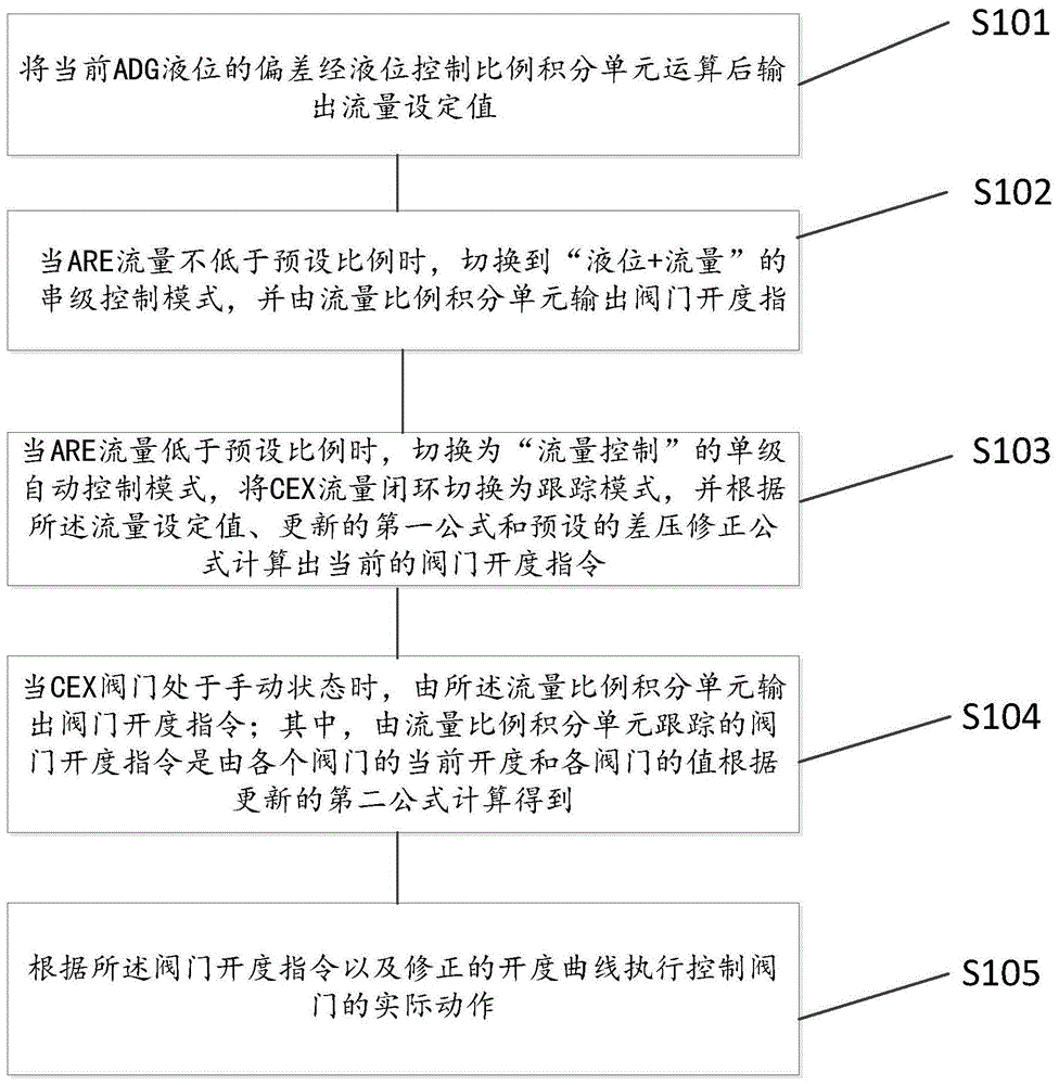
and S101, outputting a flow set value after the deviation of the current ADG liquid level is calculated by a liquid level control proportional-integral unit.
S102, when the ARE flow is not lower than the preset proportion, the cascade control mode of liquid level and flow is switched to, and a valve opening instruction is output by the flow proportion integration unit.
In this embodiment, generally, the condition for single stage to cascade switching is that neither the CEX flow nor the ARE flow is less than 20%. Because the CEX flow is both a switching trigger condition and a regulated quantity, the switching condition of the single cascade control with the CEX not lower than the threshold value of 20 percent can not be stably met, therefore, the triggering condition of switching the CEX flow to the cascade control is removed, and only the ARE flow is reserved as the condition for triggering the switching from the single stage to the cascade.
In the embodiment, for an EPR three-generation nuclear power unit, a 15% Pn time group starts to transfer; when the Pn is 25%, the unit starts to be connected to the grid; at 30% Pn, the ADG extraction check valve is opened. The ARE flow is nearly linear with loop power. Because the state and parameter change of the unit is large near 20% Pn, the switching point of single cascade switching is increased to 30%, and the disturbance of CEX flow to ADG pressure during single cascade switching can be greatly reduced. Thus, this example determines that the switching condition of single stage to cascade of ADG liquid level is ARE no less than 30% ARE flow.
And S103, when the ARE flow is lower than the preset proportion, switching to a single-stage automatic control mode of 'flow control', switching the CEX flow closed loop to a tracking mode, and calculating the current valve opening instruction according to the flow set value, the updated first formula and the preset differential pressure correction formula.
S104, when the CEX valve is in a manual state, outputting a valve opening instruction by the flow proportional-integral unit; the valve opening instruction tracked by the flow proportional integral unit is calculated by the current opening of each valve and the value of each valve according to the updated second formula.
In this embodiment, as can be seen from fig. 1, the outputs of the first and second equations are the valve opening commands for the CEX valve station. The second formula is used for manual control mode or when the CEX flow signal fails, the first formula is used for single-stage automatic control. The disturbance during the switching of the manual and automatic control modes mainly comes from the calculation of the large output deviation of the second formula and the first formula. For this reason, the present embodiment requires recalibration of the second formula and the first formula.
Specifically, the media flowing through the CEX valve are all incompressible liquids, and the flow through the valve can be calculated according to the flow calculation formula:
coefficient of flow C in the above formulaVOnly with respect to the valve characteristics.
When the actual operation working condition delta P and the design working condition delta P of the valvenWhen the deviation is large, the actual flow of the valve is as follows:
the actual through-flow capacity Q of the valve is obtained by combining two modes0And design current capacity QnThe relationship between:
the CEX valve station valve is a linear flow characteristic valve and the through-flow capacity of the entire valve station is also a linear characteristic. Therefore, for a flow rate Q, the valve station opening command Y can be calculated according to the following formula:
equation (4) corresponds to the opening demand tracking value when the valve is in the manual control mode, and corresponds to the first equation in fig. 1. By comparison, the first formula incorrectly compares C in the flow formulavThe valve opening is understood, and a differential pressure correction link is lacked.
In this embodiment, the second formula is used to calculate the valve opening tracking value according to the opening of each valve of the valve station when the valves of the CEX valve station are all in the manual control mode or when the CEX flow signal fails. The actual flow rate needs to be calculated according to the sum of the flow rates of the valves:
valve opening tracking value at this time:
the formula (6) corresponds to the second formula in the formula (1), but the second formula has wrong understanding on the Cv value, and Q is actually adoptednAnd participating in calculating the opening degree of the valve.
Therefore, the actual flow capacity of the valve is calibrated by combining the actual situation, the design flow capacity of the valve station is as follows by considering that a plurality of (taking 4 as an example) regulating valves of the valve station are connected in parallel and the design working conditions are the same:
wherein each valve Q is respectively calculatedNnValue of Q is obtainedn。
In this embodiment, a single valve is used with different valve openings Y and differentTaking the flow rate under the differential pressure Δ P condition as an example, the valve design differential pressure Δ P is setnCollecting CEX2465VL flow, differential pressure and opening data on site at 1.9bar, and removing QN<1100m3H and Y>85% of the data.
The comparison of the designed flow capacity and the actual flow capacity of the valve obtained by linear regression calculation is shown in table 1.
TABLE 1 comparison table of valve through-flow capacity values
As can be seen from table 1, the actual current capacity of the entire valve station is 36% higher than the design value. In order to ensure linearity of the opening command and the command of the valve station of the CEX, the opening curve of the valve station is further modified.
Specifically, in order to ensure a linear relationship between the valve station command and the flow rate, the valve station opening curve needs to be corrected according to the through-flow capacity of the actual valve.
TABLE 2 comparison of valve Curve relationships before and after correction
In this embodiment, since the output of the flow control proportional-integral unit does not take into account the deviation between the design condition and the actual valve station operating condition, the differential pressure correction link is separated from the equations (4) and (6), and is placed after the opening command output of the flow control proportional-integral unit.
In summary, the calculation formula of the second formula is:
the first formula is calculated as:
the processing formula of the differential pressure correction link is as follows:
and S105, executing actual action of the control valve according to the valve opening command and the corrected opening curve.
Preferably, the method further comprises the following steps:
when transient state is triggered, the PI parameter of the liquid level control proportional-integral unit is instantly switched from a steady state parameter to a transient state parameter, and the output value of the flow control proportional-integral unit responds correspondingly, so that sudden increase of the liquid level is slowed down.
The currently known transient working conditions of the unit mainly include trip and jump, trip and no-jump, no-load, service power, rapid load reduction (including a nuclear island side, an electrical side and a conventional island side) of each important system of the unit, frequency modulation of a generator and the like. Under different transient states, the unit water supply (ARE side water consumption) variable quantity is different, and when the variable quantity is smaller, the original ADG liquid level control logic PI can timely and effectively deal with the situation and maintain the liquid level to be stable. Once the variation is increased instantaneously, the response is difficult in a short time, and the liquid level is easy to rise continuously.
Therefore, as shown in fig. 4, in this embodiment, transient triggering is performed, the liquid level control is immediately switched to a transient dedicated PI parameter, and after the pulse is ended, the liquid level control is slowly switched to a steady PI parameter to perform stability adjustment, so as to maintain the final stability of the liquid level of the deaerator.
In conclusion, by adopting the embodiment, the disturbance during the switching of the ADG liquid level control mode can be greatly reduced, and the difficulty of the automatic control of the ADG liquid level is greatly reduced; the problem of the reciprocating switching of the ADG single-cascade control mode is thoroughly solved, and the overpressure of the internal pressure of the ADG and the potential safety hazard of the action of a safety valve are eliminated; the timeliness and the stability of ADG liquid level control under the transient working condition are greatly enhanced, the abnormal rising condition of the liquid level is not repeated, and the safety and the economical efficiency of the unit are greatly improved. The quality of automatic operation of the equipment is improved, the phenomenon that the unit trips due to untimely intervention or failure intervention of operators under the expected or unexpected transient working conditions is avoided, the probability of human error can be effectively reduced, and the economic loss caused by tripping is reduced.
Referring to fig. 5, a second embodiment of the present invention further provides a liquid level control device for a deaerator of a nuclear power generating unit, including:
the operation unit 210 is used for outputting a flow set value after the deviation of the current ADG liquid level is operated by the liquid level control proportional-integral unit;
the first switching unit 220 is used for switching to a cascade control mode of liquid level + flow when the ARE flow is not lower than a preset proportion, and outputting a valve opening instruction by the flow proportion integration unit;
the second switching unit 230 is configured to switch to a single-stage automatic control mode of "flow control" when the ARE flow is lower than the preset ratio, switch the CEX flow closed loop to the tracking mode, and calculate a current valve opening instruction according to the flow setting value, the updated first formula, and the preset differential pressure correction formula;
the manual control unit 240 is used for outputting a valve opening instruction by the flow proportional integral unit when the CEX valve is in a manual state; the valve opening instruction tracked by the flow proportional-integral unit is calculated by the current opening of each valve and the value of each valve according to an updated second formula;
and the execution unit 250 is used for executing the actual action of the control valve according to the valve opening instruction and the corrected opening curve.
The third embodiment of the invention also provides deaerator liquid level control equipment of a nuclear power unit, which comprises a memory and a processor, wherein a computer program is stored in the memory and can be executed by the processor, so that the deaerator liquid level control method of the nuclear power unit is realized.
In the embodiments provided in the present invention, it should be understood that the disclosed apparatus and method can be implemented in other ways. The apparatus and method embodiments described above are illustrative only, as the flowcharts and block diagrams in the figures illustrate the architecture, functionality, and operation of possible implementations of apparatus, methods and computer program products according to various embodiments of the present invention. In this regard, each block in the flowchart or block diagrams may represent a module, segment, or portion of code, which comprises one or more executable instructions for implementing the specified logical function(s). It should also be noted that, in some alternative implementations, the functions noted in the block may occur out of the order noted in the figures. For example, two blocks shown in succession may, in fact, be executed substantially concurrently, or the blocks may sometimes be executed in the reverse order, depending upon the functionality involved. It will also be noted that each block of the block diagrams and/or flowchart illustration, and combinations of blocks in the block diagrams and/or flowchart illustration, can be implemented by special purpose hardware-based systems which perform the specified functions or acts, or combinations of special purpose hardware and computer instructions.
In addition, the functional modules in the embodiments of the present invention may be integrated together to form an independent part, or each module may exist separately, or two or more modules may be integrated to form an independent part.
The functions, if implemented in the form of software functional modules and sold or used as a stand-alone product, may be stored in a computer readable storage medium. Based on such understanding, the technical solution of the present invention may be embodied in the form of a software product, which is stored in a storage medium and includes instructions for causing a computer device (which may be a personal computer, an electronic device, or a network device) to execute all or part of the steps of the method according to the embodiments of the present invention. And the aforementioned storage medium includes: a U-disk, a removable hard disk, a Read-Only Memory (ROM), a Random Access Memory (RAM), a magnetic disk or an optical disk, and other various media capable of storing program codes. It should be noted that, in this document, the terms "comprises," "comprising," or any other variation thereof, are intended to cover a non-exclusive inclusion, such that a process, method, article, or apparatus that comprises a list of elements does not include only those elements but may include other elements not expressly listed or inherent to such process, method, article, or apparatus. Without further limitation, an element defined by the phrase "comprising an … …" does not exclude the presence of other identical elements in a process, method, article, or apparatus that comprises the element.
The above description is only a preferred embodiment of the present invention and is not intended to limit the present invention, and various modifications and changes may be made by those skilled in the art. Any modification, equivalent replacement, or improvement made within the spirit and principle of the present invention should be included in the protection scope of the present invention.