Ladder stand safety protection device capable of automatically crossing cross rod
Technical Field
The invention belongs to the field of ladder climbing devices, and particularly relates to a ladder climbing safety protection device capable of automatically crossing a cross rod.
Background
The safety belt is tied when a worker works at a height of more than 2m, and the worker needs to unfasten the safety rope buckle and replace the position in the climbing process, so that the rope buckle position needs to be frequently replaced when the worker moves, and the invalid working time is increased. In addition, when a tower crane driver climbs the tower and a deep well worker climbs down to a deep well, effective protection measures for fastening and connecting the worker and the crawling ladder are lacked.
Disclosure of Invention
The invention aims to provide a ladder stand safety protection device capable of automatically crossing a cross rod, which aims to solve the problems that a worker needs to unfasten a safety rope buckle and change the position in the climbing process, frequently change the rope buckle position and increase the invalid working time; when climbing the pylon, deep well worker climbs to the deep well department down, lack the effective safeguard measure's of workman and cat ladder fastening connection technical problem.
In order to solve the above technical problems, the present invention provides a ladder safety protection device capable of automatically crossing a cross bar, comprising:
the hoop is provided with a hoop first opening end and a hoop second opening end, and the hoop second opening end is provided with a blocking part;
the stop lever is arranged between the first opening end of the hoop and the second opening end of the hoop, the stop lever is provided with a first end part of the stop lever and a second end part of the stop lever, the first end part of the stop lever is hinged with the first opening end of the hoop, a rebound mechanism of the stop lever is connected between the first end part of the stop lever and the first opening end of the hoop, and the second end part of the stop lever is propped against the bottom surface of the stop part;
rope card activation mechanism, including connecting the first spring in hoop second open end bottom, connecting the safety rope at first spring top, horizontal connection is at the bumping post of safety rope and hoop second open end lateral wall, and with the outside couple of the lateral wall swing joint of hoop second open end, the top of safety rope passes the lateral wall of hoop second open end and is connected with outside couple.
Preferably, a second spring is connected between the blocking column and the side wall of the second opening end of the hoop.
Preferably, one end of the stop pillar, which is far away from the second spring, is fixedly connected with the safety rope.
Preferably, a plurality of hoop units are connected between the first hoop opening end and the second hoop opening end, and the first hoop opening end and the hoop units, the adjacent hoop units and the second hoop opening ends are connected through adjusting plates.
Preferably, horizontal slotted holes are formed in the first hoop opening end, the second hoop opening end, the hoop units and the adjusting plate, and first bolts penetrate through the horizontal slotted holes so that the first hoop opening end is connected with the hoop units, the adjacent hoop units and the second hoop opening ends.
Preferably, the stop lever comprises a first stop lever and a second stop lever, horizontal long round holes are formed in the first stop lever and the second stop lever, and a second bolt penetrates through the horizontal long round holes to connect the first stop lever and the second stop lever.
Preferably, the side wall of the second opening end of the hoop is also movably connected with an inner side hook, and the inner side hook is connected with the top of the safety rope.
Preferably, the inner side wall of the hoop is movably connected with a ball, and the ball exceeds the inner side wall of the hoop.
Preferably, a ball limiting groove is formed in the inner side wall of the hoop, a ball fixing shaft is connected between the inner walls of the ball limiting grooves and penetrates through the balls, and the balls are limited in the ball limiting groove.
Preferably, a plurality of stop levers are arranged between the first opening end of the hoop and the second opening end of the hoop at vertical intervals, a plurality of stop parts are correspondingly arranged at the second opening end of the hoop at vertical intervals, and a plurality of stop columns are correspondingly arranged between the safety rope and the side wall of the second opening end of the hoop at vertical intervals.
Compared with the prior art, the invention has the characteristics and beneficial effects that:
(1) the invention provides a novel ladder stand safety protection device capable of automatically crossing a cross rod, which can ensure that workers can automatically cross a cross rod obstacle to move upwards/downwards while ensuring the personal safety of the workers uninterruptedly. When the workman goes upward along the cat ladder, in case the workman falls, the outside couple with workman lug connection will pull the upward movement of safety rope, and the bumping post will be along with safety rope upward movement to press from both sides the second fender pole between fender portion and bumping post, thereby avoid the emergence of incident, need not frequently change safety rope buckle position, reduce invalid operating time.
(2) The safety protection device for the crawling ladder capable of automatically crossing the cross rod can adjust the size of the hoop according to the size of the stand column of the crawling ladder, and balls are arranged on the inner side of the hoop, so that the crawling ladder can conveniently slide up and down along the vertical rod.
(3) The ladder stand safety protection device capable of automatically crossing the cross rod is clear in stress, simple in structure, light, flexible, economical and practical, and can be arranged at different protection positions according to needs. And an external power supply is not needed, and the falling worker is completely protected by the mechanical principle, so that the safety is high, and the safety is reasonable.
Drawings
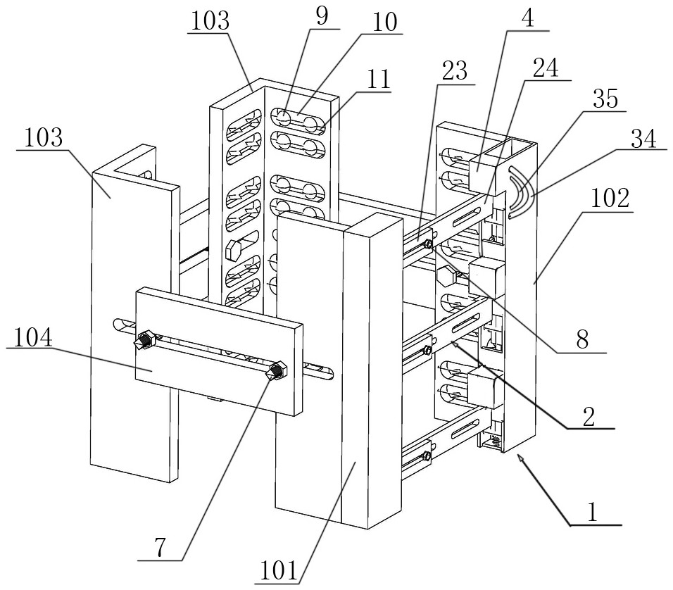
Fig. 1 is a schematic perspective view of a ladder safety protection device capable of automatically crossing a cross bar.
Fig. 2 is a schematic top view of the structure of fig. 1.
Fig. 3 is a schematic view of the cross-sectional structure a-a in fig. 2.
The attached drawings are marked as follows: 1-hoop, 101-hoop first open end, 102-hoop second open end, 103-hoop unit, 104-adjusting plate, 2-stop lever, 21-stop lever first end, 22-stop lever second end, 23-first stop lever, 24-second stop lever, 31-first spring, 32-safety rope, 33-stop column, 34-outer hook, 35-inner hook, 4-stop part, 6-second spring, 7-first bolt, 8-second bolt, 9-ball, 10-ball limit groove and 11-ball fixing shaft.
Detailed Description
In order to make the technical means, innovative features, objectives and functions realized by the present invention easy to understand, the present invention is further described below.
The examples described herein are specific embodiments of the present invention, are intended to be illustrative and exemplary in nature, and are not to be construed as limiting the scope of the invention. In addition to the embodiments described herein, those skilled in the art will be able to employ other technical solutions which are obvious based on the disclosure of the claims and the specification of the present application, and these technical solutions include technical solutions which make any obvious replacement or modification for the embodiments described herein.
In the description of the present invention, it should be noted that the terms "upper", "lower", "inner", "outer", "front", "rear", "both ends", "one end", "the other end", and the like indicate orientations or positional relationships based on those shown in the drawings, and are only for convenience of description and simplicity of description, but do not indicate or imply that the referred device or element must have a specific orientation, be constructed in a specific orientation, and be operated, and thus, should not be construed as limiting the present invention. Furthermore, the terms "first" and "second" are used for descriptive purposes only and are not to be construed as indicating or implying relative importance.
In the description of the present invention, it is to be noted that, unless otherwise explicitly specified or limited, the terms "mounted," "disposed," "connected," and the like are to be construed broadly, such as "connected," which may be fixedly connected, detachably connected, or integrally connected; can be mechanically or electrically connected; they may be connected directly or indirectly through intervening media, or they may be interconnected between two elements. The specific meanings of the above terms in the present invention can be understood in specific cases to those skilled in the art.
As shown in fig. 1-3, a ladder safety device that can automatically cross a crossbar includes a hoop 1, a bar 2, and a rope catch activation mechanism.
The hoop 1 has a hoop first open end 101 and a hoop second open end 102, the hoop second open end 102 being provided with a stop 4. The dam 4 of the present invention is preferably attached to the top sidewall of the second open end 102 of the hoop. A plurality of hoop units 103 are connected between the hoop first open end 101 and the hoop second open end 102. The hoop first open end 101 and the hoop unit 103, the adjacent hoop units 103, and the hoop unit 103 and the hoop second open end 102 are connected by an adjusting plate 104. Horizontal slotted holes are formed in the first hoop opening end 101, the second hoop opening end 102, the hoop units 103 and the adjusting plate 104, and the first bolts 7 penetrate through the horizontal slotted holes so as to connect the first hoop opening end 101 with the hoop units 103, the adjacent hoop units 103 and the hoop units 103 with the second hoop opening ends 102. The invention can change the number of the hoop units 103, adjust the relative positions between the adjusting plate 104 and the hoop first open end 101, the hoop second open end 102 and the hoop units 103, so as to adapt to the columns of different sizes of the ladder stand and improve the application range.
The inner side wall of the hoop 1 is movably connected with a ball 9, and the ball 9 exceeds the inner side wall of the hoop 1. The inside wall of the hoop 1 is provided with a ball limiting groove 10, a ball fixing shaft 11 is connected between the inner walls of the ball limiting groove 10, the ball fixing shaft 11 penetrates through the ball 9, and the ball 9 is limited in the ball limiting groove 10. The ball 9 can roll up and down, further limiting the relative displacement between the stand column of the ladder and the safety protection device of the invention, and ensuring that the safety protection device can only move up and down along the stand column of the ladder.
The stop lever 2 is arranged between the first hoop opening end 101 and the second hoop opening end 102, the stop lever 2 is provided with a first stop lever end part 21 and a second stop lever end part 22, the first stop lever end part 21 is hinged with the first hoop opening end 101, a stop lever rebounding mechanism is connected between the first stop lever end part 21 and the first hoop opening end 101, and the second stop lever end part 22 is pressed against the bottom surface of the stop part 4. When the safety protection device ascends along the crawling ladder and meets the cross rod of the crawling ladder, the stop lever 2 can touch the crawling ladder cross rod and rotate downwards, and when the crawling ladder cross rod completely enters the area between the adjacent stop levers 2, the stop lever rebounding mechanism drives the first end part 21 of the stop lever to move and automatically return to the original position. The bar rebounding mechanism may be a spring, and any structure that automatically rebounds the first end 21 of the bar is within the scope of the present invention.
The stop lever 2 comprises a first stop lever 23 and a second stop lever 24, horizontal long round holes are formed in the first stop lever 23 and the second stop lever 24, and the second bolt 8 penetrates through the horizontal long round holes to connect the first stop lever 23 and the second stop lever 24. By varying the relative positions of the first and second bars 23, 24, ladder stand columns of different sizes can be accommodated.
The rope clamp activation mechanism comprises a first spring 31 connected to the bottom of the second open end 102 of the hoop, a safety rope 32 connected to the top of the first spring 31, a stop pillar 33 horizontally connected to the side wall of the safety rope 32 and the second open end 102 of the hoop, and an outer hook 34 movably connected to the side wall of the second open end 102 of the hoop, wherein the top end of the safety rope 32 penetrates through the side wall of the second open end 102 of the hoop and is connected with the outer hook 34. The side wall of the second opening end 102 of the hoop is also movably connected with an inner side hook 35, and the inner side hook 35 is connected with the top of the safety rope 32. The thickness of the outer hooks 34 is greater than the thickness of the inner hooks 35. A second spring 6 is connected between the abutment 33 and the sidewall of the second open end 102 of the hoop. The end of the stop pillar 33 remote from the second spring 6 is fixedly connected with the safety line 32. Specifically, one end of the catch 33 away from the second spring 6 is provided with a catch spring, and the catch 33 is fixedly connected with the safety rope 32 through the catch spring.
A plurality of stop rods 2 are arranged between the first hoop opening end 101 and the second hoop opening end 102 at vertical intervals, a plurality of stop parts 4 are correspondingly arranged at the second hoop opening end 102 at vertical intervals, and a plurality of stop columns 33 are correspondingly arranged between the safety rope 32 and the side wall of the second hoop opening end 102 at vertical intervals.
When workers need to go up along the ladder stand, the stop lever 2 is rotated, and the device is sleeved outside the stand column of the ladder stand. The worker directly attaches to the outside hitch 34. In the ascending process of the device, when the stop lever 2 meets the ladder climbing cross rod, the stop lever 2 rotates downwards by taking the end part of the first stop lever 23 as an axial direction until the ladder climbing cross rod completely enters the area between the adjacent stop levers 2. If the worker falls, the outer hook 34 pulls the safety rope 32 to move upwards, and the stop pillar 33 fixedly connected with the safety rope 32 moves upwards along with the safety rope until the safety rope abuts against the bottom surface of the second stop lever 24, so that the second stop lever 24 is clamped between the stop pillar 33 and the stop part 4, and the worker is prevented from further falling.
When workers need to descend along the crawling ladder, the stop lever 2 is rotated, and the protection device is reversely sleeved outside the crawling ladder stand column. The worker is directly connected to both the outside hook 34 and the inside hook 35 at the same time. In the descending process of the device, when the stop lever 2 meets the ladder climbing cross rod, the stop lever 2 rotates in the axial direction by taking the end part of the first stop lever 23 as the axial direction until the ladder climbing cross rod completely enters the area between the adjacent stop levers 2. If the worker falls, the outer side hook 34 and the inner side hook 35 simultaneously pull the safety rope 32 to move downwards, the stop pillar 33 fixedly connected with the safety rope 32 moves downwards along with the safety rope until the safety rope abuts against the top surface of the second stop lever 24, and then the second stop lever 24 is clamped between the stop pillar 33 and the stop part 4, so that the worker is prevented from further falling.
The above examples are only for describing the preferred embodiments of the present invention, and are not intended to limit the scope of the present invention, and various modifications and improvements made to the technical solution of the present invention by those skilled in the art without departing from the spirit of the present invention should fall within the protection scope defined by the claims of the present invention.