CN113124792B - Method for measuring bonding area of large-scale high-speed rotating equipment based on non-contact ultrasound - Google Patents
Method for measuring bonding area of large-scale high-speed rotating equipment based on non-contact ultrasound Download PDFInfo
- Publication number
- CN113124792B CN113124792B CN201911411995.XA CN201911411995A CN113124792B CN 113124792 B CN113124792 B CN 113124792B CN 201911411995 A CN201911411995 A CN 201911411995A CN 113124792 B CN113124792 B CN 113124792B
- Authority
- CN
- China
- Prior art keywords
- rotor component
- laser
- lens
- bonding area
- perot interferometer
- Prior art date
- Legal status (The legal status is an assumption and is not a legal conclusion. Google has not performed a legal analysis and makes no representation as to the accuracy of the status listed.)
- Active
Links
Images

Classifications
-
- G—PHYSICS
- G01—MEASURING; TESTING
- G01B—MEASURING LENGTH, THICKNESS OR SIMILAR LINEAR DIMENSIONS; MEASURING ANGLES; MEASURING AREAS; MEASURING IRREGULARITIES OF SURFACES OR CONTOURS
- G01B17/00—Measuring arrangements characterised by the use of infrasonic, sonic or ultrasonic vibrations
-
- G—PHYSICS
- G01—MEASURING; TESTING
- G01B—MEASURING LENGTH, THICKNESS OR SIMILAR LINEAR DIMENSIONS; MEASURING ANGLES; MEASURING AREAS; MEASURING IRREGULARITIES OF SURFACES OR CONTOURS
- G01B11/00—Measuring arrangements characterised by the use of optical techniques
- G01B11/28—Measuring arrangements characterised by the use of optical techniques for measuring areas
- G01B11/285—Measuring arrangements characterised by the use of optical techniques for measuring areas using photoelectric detection means
-
- G—PHYSICS
- G01—MEASURING; TESTING
- G01M—TESTING STATIC OR DYNAMIC BALANCE OF MACHINES OR STRUCTURES; TESTING OF STRUCTURES OR APPARATUS, NOT OTHERWISE PROVIDED FOR
- G01M15/00—Testing of engines
-
- G—PHYSICS
- G01—MEASURING; TESTING
- G01M—TESTING STATIC OR DYNAMIC BALANCE OF MACHINES OR STRUCTURES; TESTING OF STRUCTURES OR APPARATUS, NOT OTHERWISE PROVIDED FOR
- G01M15/00—Testing of engines
- G01M15/14—Testing gas-turbine engines or jet-propulsion engines
Landscapes
- Physics & Mathematics (AREA)
- General Physics & Mathematics (AREA)
- Chemical & Material Sciences (AREA)
- Engineering & Computer Science (AREA)
- Combustion & Propulsion (AREA)
- Length Measuring Devices By Optical Means (AREA)
- Investigating Or Analyzing Materials By The Use Of Ultrasonic Waves (AREA)
Abstract
本发明提出了基于非接触超声的大型高速回转装备贴合面积测量方法,使激光器发射的脉冲激光通过分光镜和第一透镜照射在第一转子部件的上表面;使光电探测器接收到来自分光镜的脉冲激光;使共焦Fabry‑Perot干涉仪能够接收到第一转子部件上表面的超声信号;数据采集卡将由光电探测器传入的电信号和共焦Fabry‑Perot干涉仪传入的超声波信号转换为数字信号,将数字信号传输至工控机进行保存和数据处理;利用振幅Ai与贴合面积Si间的对应关系,获得当前检测位置上第一转子部件与第二转子部件的贴合面积。本发明实现了大型高速回转装备贴合面积的非接触式无损测量,同时激光超声的激发和接收均在瞬间完成,能够实现快速、实时测量,具有较强的抗干扰能力。
The invention proposes a method for measuring the bonding area of large-scale high-speed rotating equipment based on non-contact ultrasound, so that the pulsed laser emitted by the laser is irradiated on the upper surface of the first rotor part through the beam splitter and the first lens; The pulsed laser of the mirror; enables the confocal Fabry-Perot interferometer to receive the ultrasonic signal on the upper surface of the first rotor part; the data acquisition card combines the electrical signal from the photodetector with the ultrasonic wave from the confocal Fabry-Perot interferometer The signal is converted into a digital signal, and the digital signal is transmitted to the industrial computer for storage and data processing; using the corresponding relationship between the amplitude A i and the bonding area Si , the bonding between the first rotor part and the second rotor part at the current detection position is obtained. combined area. The invention realizes the non-contact non-destructive measurement of the bonding area of large-scale high-speed rotary equipment, and simultaneously the excitation and reception of laser ultrasound are completed in an instant, which can realize fast and real-time measurement, and has strong anti-interference ability.
Description
技术领域technical field
本发明涉及基于非接触超声的大型高速回转装备贴合面积测量方法,属于测量技术领域。The invention relates to a method for measuring the bonding area of large-scale high-speed rotary equipment based on non-contact ultrasound, and belongs to the technical field of measurement.
背景技术Background technique
航空发动机或燃气轮机等大型高速回转装备,由于技术复杂,研制难度大等特点,加上欧美技术封锁,已成为我国高端装备制造领域中的卡脖子问题。航空发动机或燃气轮机系统一般由多级转子装配而成,转子之间相互接触的表面称为结合面。这些在微观上是粗糙的接触面使系统不再具有连续性。航空发动机或燃气轮机系统的力学性质不但与转子零件本身有关,还与转子之间的连接性质有关,结合面的存在使系统性能的分析和预测变得复杂。各级转子之间的装配质量对航空发动机或燃气轮机等大型高速回转装备的性能具有非常大的影响。在装配过程中,转子连接界面若存在贴合面积的不均匀性,将使航空发动机或燃气轮机在高速状态下产生的变形量存在不均匀性,转子的不平衡量就存在较大的变化,最终导致发动机在工作时产生振动。涡扇航空发动机90%以上的故障源于振动,这就是我国航空发动机工作几百小时就要大修的根源之一。所以,迫切要求精密测量发动机转子的贴合面积,只有测量精密,才能装配的精准。Large-scale high-speed slewing equipment such as aero-engines or gas turbines has become a bottleneck problem in the field of high-end equipment manufacturing in my country due to its complex technology, difficult development and other characteristics, coupled with European and American technology blockades. Aero-engine or gas turbine systems are generally assembled from multi-stage rotors, and the surfaces of the rotors in contact with each other are called joint surfaces. These microscopically rough contact surfaces make the system no longer continuous. The mechanical properties of an aero-engine or gas turbine system are not only related to the rotor parts themselves, but also to the connection properties between the rotors. The existence of joint surfaces complicates the analysis and prediction of system performance. The assembly quality between the rotors at all levels has a great impact on the performance of large-scale high-speed rotary equipment such as aero-engines or gas turbines. During the assembly process, if there is non-uniformity in the bonding area of the rotor connection interface, the deformation of the aero-engine or gas turbine at high speed will be non-uniform, and the imbalance of the rotor will change greatly, which will eventually lead to The engine vibrates during operation. More than 90% of the failures of turbofan aero-engines originate from vibration, which is one of the reasons why my country's aero-engines need to be overhauled after working for hundreds of hours. Therefore, it is urgent to precisely measure the bonding area of the engine rotor. Only when the measurement is precise, can the assembly be accurate.
目前贴合面积的测量主要是通过在转子接触界面设置压敏薄膜或者涂抹红丹粉,通过观察装配后压敏薄膜或者红丹粉的变化来判断接触情况,进而推算出贴合面积,此类方法改变了界面的接触状态,不能反映真实的接触情况,影响测量结果。超声波方法可以在不改变工件的接触状态的情况下实现对结合面接触特性的无损测量,利用超声探头对结合面进行扫描可以直接得到名义接触面积,因而国内外学者对超声测量方法开展了广泛研究。传统的超声技术多采用接触式换能器,为保证有高的灵敏度和可靠性,通常还应使用各种超声耦合剂,超声波在穿越禪合剂时需要一定的渡越时间,并且会产生干扰谐波,给测量带来不稳定的因素,并且耦合剂的使用会对增加额外的工作量,导致测量效率低,更严重的是会对航空发动机或燃气轮机转子表面造成一定的腐蚀和伤害,因而在实际应用中传统的超声波法受到了一定的限制。At present, the measurement of the bonding area is mainly by setting a pressure-sensitive film or applying red dan powder on the contact interface of the rotor, and by observing the change of the pressure-sensitive film or red dan powder after assembly to judge the contact situation, and then calculate the bonding area. The method changes the contact state of the interface, which cannot reflect the real contact situation and affects the measurement results. The ultrasonic method can achieve non-destructive measurement of the contact characteristics of the joint surface without changing the contact state of the workpiece. The nominal contact area can be directly obtained by scanning the joint surface with an ultrasonic probe. Therefore, scholars at home and abroad have carried out extensive research on ultrasonic measurement methods. . Traditional ultrasonic technology mostly uses contact transducers. In order to ensure high sensitivity and reliability, various ultrasonic couplants are usually used. Ultrasonic waves need a certain transit time when passing through the coupling agent, and will produce interference harmonics. wave, which will bring unstable factors to the measurement, and the use of couplant will increase the extra workload, resulting in low measurement efficiency, and more seriously, it will cause certain corrosion and damage to the surface of the aero-engine or gas turbine rotor. The traditional ultrasonic method is limited in practical application.
发明内容SUMMARY OF THE INVENTION
本发明提出基于非接触超声的大型高速回转装备贴合面积测量方法,其目的是为了解决大型高速回转装备贴合面积难以直接测量、传统的超声波法测量效率低且会对被测件表面造成腐蚀等问题,实现大型高速回转装备贴合面积的直接、高效率和高精度测量。The present invention proposes a method for measuring the bonding area of large-scale high-speed rotary equipment based on non-contact ultrasound. and other problems, to achieve direct, high-efficiency and high-precision measurement of the bonding area of large-scale high-speed rotary equipment.
基于非接触超声的大型高速回转装备贴合面积测量方法,应用于基于激光超声的大型高速回转装备贴合面积测量装置,所述测量装置包括:激光器、分光镜、第一透镜、共焦Fabry-Perot干涉仪、数据采集卡、第二透镜、光电探测器、工控机、第一转子部件和第二转子部件,所述共焦Fabry-Perot干涉仪的输出端和所述光电探测器的输出端均通过所述数据采集卡与所述工控机的输入端连接,所述工控机的输出端分别与所述激光器的输入端和Fabry-Perot干涉仪的输入端连接,所述激光器、分光镜和第一透镜相对所述第一转子部件由远及近依次设置在所述第一转子部件的斜上方45°角上,所述激光器与所述第一透镜同轴设置,所述光电探测器和所述第二透镜相对所述分光镜由远及近依次同轴设置在所述分光镜的反射光路上,所述共焦Fabry-Perot干涉仪设置在所述第一转子部件的上方,所述第一转子部件与所述第二转子部件通过法兰螺栓结构连接,所述测量方法包括以下步骤:A method for measuring the bonding area of large-scale high-speed rotary equipment based on non-contact ultrasound is applied to a large-scale high-speed rotary equipment bonding area measurement device based on laser ultrasound. The measurement device includes: a laser, a beam splitter, a first lens, a confocal Fabry- Perot interferometer, data acquisition card, second lens, photodetector, industrial computer, first rotor part and second rotor part, the output end of the confocal Fabry-Perot interferometer and the output end of the photodetector All are connected to the input end of the industrial computer through the data acquisition card, and the output end of the industrial computer is respectively connected to the input end of the laser and the input end of the Fabry-Perot interferometer. The first lens is arranged at an angle of 45° obliquely above the first rotor member from far to near relative to the first rotor member, the laser is arranged coaxially with the first lens, the photodetector and the The second lens is coaxially arranged on the reflected light path of the spectroscope from far to near relative to the spectroscope, the confocal Fabry-Perot interferometer is arranged above the first rotor part, and the The first rotor part and the second rotor part are connected by a flange bolt structure, and the measurement method includes the following steps:
步骤一、调整所述激光器、分光镜和第一透镜的位置及姿态,使所述激光器发射的脉冲激光通过所述分光镜和第一透镜照射在所述第一转子部件的上表面;Step 1: Adjust the position and posture of the laser, the spectroscope and the first lens, so that the pulsed laser emitted by the laser is irradiated on the upper surface of the first rotor part through the spectroscope and the first lens;
步骤二、调整所述第二透镜和光电探测器的位置及姿态,使所述光电探测器接收到来自分光镜的脉冲激光;Step 2: Adjust the position and attitude of the second lens and the photodetector, so that the photodetector receives the pulsed laser light from the beam splitter;
步骤三,调整共焦Fabry-Perot干涉仪的位置及姿态,使共焦Fabry-Perot干涉仪能够接收到第一转子部件上表面的超声信号;
步骤四、所述工控机发送指令使激光器发射脉冲激光,脉冲激光被所述分光镜分成两束,其中一束脉冲激光经过所述第二透镜入射到光电探测器后转换为电信号传输至所述数据采集卡,作为超声信号的采集触发,另一束脉冲激光经过第一透镜后聚焦到第一转子部件的上表面并在第一转子部件内部激发出超声波,超声波在第一转子部件内部传播并到达第一转子部件与第二转子部件的结合面,一部分超声波穿过所述结合面继续传播,另一部分超声波反射回第一转子部件的上表面被共焦Fabry-Perot干涉仪接收并传输至数据采集卡,数据采集卡将由共焦Fabry-Perot干涉仪传入的超声波信号和光电探测器传入的电信号转换为数字信号,将所述数字信号传输至工控机进行保存和数据处理;Step 4. The industrial computer sends an instruction to make the laser emit pulsed laser light. The pulsed laser light is divided into two beams by the beam splitter. One of the pulsed laser beams is incident on the photodetector through the second lens and is converted into an electrical signal and transmitted to the The data acquisition card is used as a trigger for the acquisition of ultrasonic signals. After passing through the first lens, another pulsed laser is focused on the upper surface of the first rotor part and excites ultrasonic waves inside the first rotor part, and the ultrasonic waves propagate inside the first rotor part. And reach the joint surface of the first rotor part and the second rotor part, part of the ultrasonic wave continues to propagate through the joint surface, and another part of the ultrasonic wave is reflected back to the upper surface of the first rotor part to be received by the confocal Fabry-Perot interferometer and transmitted to Data acquisition card, the data acquisition card converts the ultrasonic signal from the confocal Fabry-Perot interferometer and the electrical signal from the photodetector into digital signals, and transmits the digital signals to the industrial computer for storage and data processing;
步骤五、在数据信号中提取超声波信号Vi的振幅Ai,利用振幅Ai与贴合面积Si之间的对应关系,获得当前检测位置上第一转子部件与第二转子部件的贴合面积。
进一步的,在步骤五中,所述振幅Ai与贴合面积Si之间的对应关系通过标定得出,即:Further, in
Si=CAi (1)S i =CA i (1)
其中,C为实验标定得出的超声信号振幅Ai与贴合面积Si之间的关系系数。Among them, C is the relationship coefficient between the ultrasonic signal amplitude A i and the bonding area Si obtained from the experimental calibration .
本发明具有以下有益效果:The present invention has the following beneficial effects:
(1)采用激光器和共焦Fabry-Perot干涉仪分别实现超声法的激励和接收,实现贴合面积的非接触式无损测量,能够避免使用传统超声波方法中所必需的液体耦合剂,因此消除了耦合剂对被测件表面的腐蚀和污染,同时激光超声的激发和接收均在瞬间完成,能够实现快速、实时测量,具有较强的抗干扰能力;(1) The laser and the confocal Fabry-Perot interferometer are used to realize the excitation and reception of the ultrasonic method respectively, and the non-contact non-destructive measurement of the bonding area can be realized, which can avoid the use of the liquid couplant necessary in the traditional ultrasonic method, thus eliminating the need for The couplant corrodes and contaminates the surface of the test piece, and the excitation and reception of laser ultrasound are completed in an instant, which can realize fast and real-time measurement, and has strong anti-interference ability;
(2)激光束可被聚焦成非常小的点,因此能够提高大型高速回转装备贴合面积测量的空间分辨率。(2) The laser beam can be focused into a very small point, so the spatial resolution of the measurement of the bonding area of large-scale high-speed rotary equipment can be improved.
附图说明Description of drawings
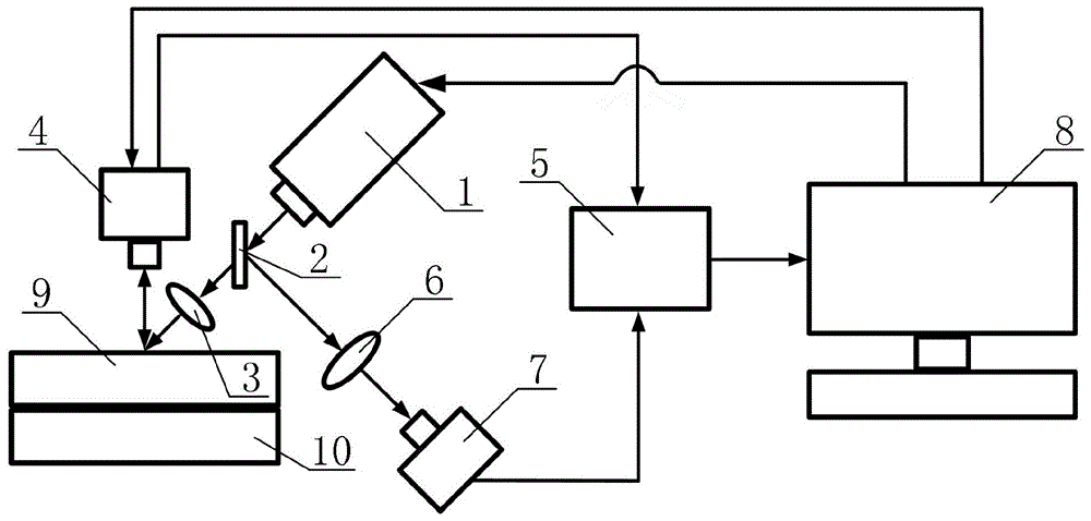
图1为基于激光超声的大型高速回转装备贴合面积测量装置的结构示意图。Figure 1 is a schematic diagram of the structure of a large-scale high-speed rotary equipment bonding area measurement device based on laser ultrasound.
其中,1为激光器、2为分光镜、3为第一透镜、4为共焦Fabry-Perot干涉仪、5为数据采集卡、6为第二透镜、7为光电探测器、8为工控机、9为第一转子部件、10为第二转子部件。Among them, 1 is the laser, 2 is the beam splitter, 3 is the first lens, 4 is the confocal Fabry-Perot interferometer, 5 is the data acquisition card, 6 is the second lens, 7 is the photodetector, 8 is the industrial computer, 9 is the first rotor part and 10 is the second rotor part.
具体实施方式Detailed ways
下面将结合本发明实施例中的附图对本发明实施例中的技术方案进行清楚、完整地描述,显然,所描述的实施例仅仅是本发明一部分实施例,而不是全部的实施例。基于本发明中的实施例,本领域普通技术人员在没有做出创造性劳动前提下所获得的所有其他实施例,都属于本发明保护的范围。The technical solutions in the embodiments of the present invention will be clearly and completely described below with reference to the accompanying drawings in the embodiments of the present invention. Obviously, the described embodiments are only a part of the embodiments of the present invention, but not all of the embodiments. Based on the embodiments of the present invention, all other embodiments obtained by those of ordinary skill in the art without creative efforts shall fall within the protection scope of the present invention.
参照图1所示,基于非接触超声的大型高速回转装备贴合面积测量方法,应用于基于激光超声的大型高速回转装备贴合面积测量装置,测量装置包括:激光器1、分光镜2、第一透镜3、共焦Fabry-Perot干涉仪4、数据采集卡5、第二透镜6、光电探测器7、工控机8、第一转子部件9和第二转子部件10,共焦Fabry-Perot干涉仪4的输出端和光电探测器7的输出端均通过数据采集卡5与工控机8的输入端连接,工控机8的输出端分别与激光器1的输入端和Fabry-Perot干涉仪4的输入端连接,激光器1、分光镜2和第一透镜3相对第一转子部件9由远及近依次设置在第一转子部件9的斜上方45°角上,激光器1与第一透镜3同轴设置,光电探测器7和第二透镜6相对分光镜2由远及近依次同轴设置在分光镜2的反射光路上,共焦Fabry-Perot干涉仪4设置在第一转子部件9的上方,第一转子部件9与第二转子部件10通过法兰螺栓结构连接,测量方法包括以下步骤:Referring to Figure 1, the method for measuring the bonding area of large-scale high-speed rotary equipment based on non-contact ultrasound is applied to a large-scale high-speed rotary equipment bonding area measurement device based on laser ultrasound. The measurement device includes: a laser 1, a
步骤一、调整激光器1、分光镜2和第一透镜3的位置及姿态,使激光器1发射的脉冲激光通过分光镜2和第一透镜3照射在第一转子部件9的上表面;Step 1, adjust the position and attitude of the laser 1, the
步骤二、调整第二透镜6和光电探测器7的位置及姿态,使光电探测器7接收到来自分光镜2的脉冲激光;
步骤三,调整共焦Fabry-Perot干涉仪4的位置及姿态,使共焦Fabry-Perot干涉仪4能够接收到第一转子部件9上表面的超声信号;
步骤四、工控机8发送指令使激光器1发射脉冲激光,脉冲激光被分光镜2分成两束,其中一束脉冲激光经过第二透镜6入射到光电探测器7后转换为电信号传输至数据采集卡5,作为超声信号的采集触发,另一束脉冲激光经过第一透镜3后聚焦到第一转子部件9的上表面并在第一转子部件9内部激发出超声波,超声波在第一转子部件9内部传播并到达第一转子部件9与第二转子部件10的结合面,一部分超声波穿过结合面继续传播,另一部分超声波反射回第一转子部件9的上表面被共焦Fabry-Perot干涉仪4接收并传输至数据采集卡5,数据采集卡5将由共焦Fabry-Perot干涉仪4传入的超声波信号和光电探测器7传入的电信号转换为数字信号,将数字信号传输至工控机8进行保存和数据处理;Step 4. The industrial computer 8 sends an instruction to make the laser 1 emit pulsed laser light. The pulsed laser light is divided into two beams by the
步骤五、在数据信号中提取超声波信号Vi的振幅Ai,利用振幅Ai与贴合面积Si之间的对应关系,获得当前检测位置上第一转子部件9与第二转子部件10的贴合面积。Step 5: Extract the amplitude A i of the ultrasonic signal V i from the data signal, and use the corresponding relationship between the amplitude A i and the bonding area S i to obtain the current detection position of the
在本部分优选实施例中,在步骤五中,所述振幅Ai与贴合面积Si之间的对应关系通过标定得出,即:In the preferred embodiment of this part, in
Si=CAi (1)S i =CA i (1)
其中,C为实验标定得出的超声信号振幅Ai与贴合面积Si之间的关系系数。Among them, C is the relationship coefficient between the ultrasonic signal amplitude A i and the bonding area Si obtained from the experimental calibration .
具体的,工控机8控制激光器1发出激光的时间、脉冲能量以及激光发射频率。Specifically, the industrial computer 8 controls the time, pulse energy and laser emission frequency of the laser 1 to emit laser light.
本发明所述的大型高速回转装备以对象为例就是如航空发动机或燃气轮机,具体限定为被测件尺寸高度大于3m,直径大于1.5m,转速大于1.5万转每分钟的回转装备。The large-scale high-speed rotary equipment described in the present invention takes objects such as aero-engines or gas turbines as an example, and is specifically limited to the rotary equipment whose size and height are greater than 3m, diameter is greater than 1.5m, and rotational speed is greater than 15,000 rpm.
Claims (2)
Priority Applications (1)
| Application Number | Priority Date | Filing Date | Title |
|---|---|---|---|
| CN201911411995.XA CN113124792B (en) | 2019-12-31 | 2019-12-31 | Method for measuring bonding area of large-scale high-speed rotating equipment based on non-contact ultrasound |
Applications Claiming Priority (1)
| Application Number | Priority Date | Filing Date | Title |
|---|---|---|---|
| CN201911411995.XA CN113124792B (en) | 2019-12-31 | 2019-12-31 | Method for measuring bonding area of large-scale high-speed rotating equipment based on non-contact ultrasound |
Publications (2)
| Publication Number | Publication Date |
|---|---|
| CN113124792A CN113124792A (en) | 2021-07-16 |
| CN113124792B true CN113124792B (en) | 2022-10-25 |
Family
ID=76770430
Family Applications (1)
| Application Number | Title | Priority Date | Filing Date |
|---|---|---|---|
| CN201911411995.XA Active CN113124792B (en) | 2019-12-31 | 2019-12-31 | Method for measuring bonding area of large-scale high-speed rotating equipment based on non-contact ultrasound |
Country Status (1)
| Country | Link |
|---|---|
| CN (1) | CN113124792B (en) |
Families Citing this family (2)
| Publication number | Priority date | Publication date | Assignee | Title |
|---|---|---|---|---|
| CN112903819A (en) * | 2019-12-03 | 2021-06-04 | 哈尔滨工业大学 | Large-scale high-speed rotation equipment defect detection method based on ultrasonic principle |
| CN116713217B (en) * | 2023-05-11 | 2025-11-28 | 南京北路智控科技股份有限公司 | Dust removing method and system for camera, electronic equipment and storage medium |
Family Cites Families (10)
| Publication number | Priority date | Publication date | Assignee | Title |
|---|---|---|---|---|
| US5523839A (en) * | 1994-02-28 | 1996-06-04 | Minnesota Mining & Manufacturing | Differential optical interferometric profilomenty for real time manufacturing control |
| CN1189746C (en) * | 2002-03-21 | 2005-02-16 | 江苏大学 | Nondestructive quantitative testing method and device for photoacoustic performance of film-based coupling structure of micro-opto-electro-mechanical system |
| DE10236756A1 (en) * | 2002-08-10 | 2004-02-19 | Sms Meer Gmbh | Device for measuring the wall thickness of a pipe in a rolling mill has lamp emitting a bundled light and fixed to different sites on a measuring head |
| JP2005147870A (en) * | 2003-11-17 | 2005-06-09 | Fujinon Corp | Method of measuring optical interference of detour surface and interferometer device for detour surface measurement |
| JP4496154B2 (en) * | 2005-10-31 | 2010-07-07 | 株式会社リコー | Rotary encoder, roller member, belt conveying device, image forming device |
| CN101377410A (en) * | 2008-10-10 | 2009-03-04 | 哈尔滨工业大学 | Large caliber aspheric surface measuring apparatus and method based on ultra-precise revolving scanning |
| CN101666628B (en) * | 2009-09-22 | 2010-12-01 | 哈尔滨工业大学 | Large-diameter convex aspheric two-axis splicing measuring device |
| JP5842246B2 (en) * | 2011-05-16 | 2016-01-13 | 一般財団法人生産技術研究奨励会 | Viscosity / elasticity measuring apparatus and method |
| JP5967924B2 (en) * | 2011-12-21 | 2016-08-10 | キヤノン株式会社 | Position detection apparatus, imprint apparatus, and device manufacturing method |
| CN106625398B (en) * | 2017-01-03 | 2019-05-14 | 哈尔滨工业大学 | An aero-engine rotor assembly method and device |
-
2019
- 2019-12-31 CN CN201911411995.XA patent/CN113124792B/en active Active
Also Published As
| Publication number | Publication date |
|---|---|
| CN113124792A (en) | 2021-07-16 |
Similar Documents
| Publication | Publication Date | Title |
|---|---|---|
| CN110376285B (en) | A method and device for ultrasonic detection of cracks on the tooth surface of ordinary threads of tie rod bolts | |
| US6736011B2 (en) | Inspection of shrunk-on steam turbine disks using advanced ultrasonic techniques | |
| CN110082428B (en) | Method for measuring elastic constant of material based on combination of crack tip effect and laser ultrasound | |
| CN114113321B (en) | Phased array ultrasonic detection system and method for blade root groove of gas turbine compressor impeller | |
| CN101858890A (en) | Small size material shallow defect detection system | |
| CN113124792B (en) | Method for measuring bonding area of large-scale high-speed rotating equipment based on non-contact ultrasound | |
| CN107091877A (en) | The laser-ultrasound lossless detection method of laser injection fibre and coherent detection | |
| CN204758470U (en) | Laser ultrasonic testing device | |
| CN103674359A (en) | Method and device for laser ultrasonic non-destructive testing of residual stress of composite material | |
| CN106996962A (en) | The Laser-Ultrasonic Nondestructive Testing System of laser injection fibre and coherent detection | |
| CN106053612B (en) | Probe and detection method for the detection of EMU axle-mounted brake disk hub mounting base | |
| CN110687204A (en) | Laser ultrasonic detection method and device | |
| JP2010175340A (en) | Plate thickness measuring method and plate thickness measuring apparatus | |
| CN103822968B (en) | Pressure-ultrasonic reflection rate curve construction method towards the detection of faying face pressure | |
| CN117092218A (en) | Ultrasonic phased array surface leakage wave full focusing imaging method based on root mean square speed | |
| CN113124793B (en) | Large-scale high-speed rotation equipment laminating area measuring device based on laser supersound | |
| CN103336013A (en) | Photoacoustic detection device for bonding strength of photosensitive chip in sealing environment | |
| CN211627451U (en) | A device for laser ultrasonic testing | |
| CN110849517B (en) | Measurement method of assembly fastening force of large-scale high-speed rotary equipment based on acoustic-elastic effect | |
| CN112903156B (en) | Method for measuring axial stress of large-sized high-speed rotary equipment based on non-contact propagation | |
| CN104990521A (en) | Non-contact type composite material thickness measurement device and method | |
| JP5577194B2 (en) | Thermal insulation under-corrosion detection device and thermal insulation under-corrosion inspection method | |
| CN110763766A (en) | Laser ultrasonic phase-locking detection system and method for turbine blade surface microdefects | |
| CN217521085U (en) | An ultrasonic stress transducer directivity measurement device | |
| CN112611804B (en) | Wind power bolt phased array test block, system and detection method |
Legal Events
| Date | Code | Title | Description |
|---|---|---|---|
| PB01 | Publication | ||
| PB01 | Publication | ||
| SE01 | Entry into force of request for substantive examination | ||
| SE01 | Entry into force of request for substantive examination | ||
| GR01 | Patent grant | ||
| GR01 | Patent grant |