CN1131981A - journal bearing - Google Patents
journal bearing Download PDFInfo
- Publication number
- CN1131981A CN1131981A CN95190767A CN95190767A CN1131981A CN 1131981 A CN1131981 A CN 1131981A CN 95190767 A CN95190767 A CN 95190767A CN 95190767 A CN95190767 A CN 95190767A CN 1131981 A CN1131981 A CN 1131981A
- Authority
- CN
- China
- Prior art keywords
- bearing
- oiling agent
- groove
- internal surface
- length
- Prior art date
- Legal status (The legal status is an assumption and is not a legal conclusion. Google has not performed a legal analysis and makes no representation as to the accuracy of the status listed.)
- Pending
Links
Images


Classifications
-
- F—MECHANICAL ENGINEERING; LIGHTING; HEATING; WEAPONS; BLASTING
- F16—ENGINEERING ELEMENTS AND UNITS; GENERAL MEASURES FOR PRODUCING AND MAINTAINING EFFECTIVE FUNCTIONING OF MACHINES OR INSTALLATIONS; THERMAL INSULATION IN GENERAL
- F16C—SHAFTS; FLEXIBLE SHAFTS; ELEMENTS OR CRANKSHAFT MECHANISMS; ROTARY BODIES OTHER THAN GEARING ELEMENTS; BEARINGS
- F16C33/00—Parts of bearings; Special methods for making bearings or parts thereof
- F16C33/02—Parts of sliding-contact bearings
- F16C33/04—Brasses; Bushes; Linings
- F16C33/06—Sliding surface mainly made of metal
- F16C33/10—Construction relative to lubrication
- F16C33/1025—Construction relative to lubrication with liquid, e.g. oil, as lubricant
- F16C33/106—Details of distribution or circulation inside the bearings, e.g. details of the bearing surfaces to affect flow or pressure of the liquid
- F16C33/1065—Grooves on a bearing surface for distributing or collecting the liquid
-
- F—MECHANICAL ENGINEERING; LIGHTING; HEATING; WEAPONS; BLASTING
- F16—ENGINEERING ELEMENTS AND UNITS; GENERAL MEASURES FOR PRODUCING AND MAINTAINING EFFECTIVE FUNCTIONING OF MACHINES OR INSTALLATIONS; THERMAL INSULATION IN GENERAL
- F16C—SHAFTS; FLEXIBLE SHAFTS; ELEMENTS OR CRANKSHAFT MECHANISMS; ROTARY BODIES OTHER THAN GEARING ELEMENTS; BEARINGS
- F16C17/00—Sliding-contact bearings for exclusively rotary movement
- F16C17/02—Sliding-contact bearings for exclusively rotary movement for radial load only
-
- F—MECHANICAL ENGINEERING; LIGHTING; HEATING; WEAPONS; BLASTING
- F16—ENGINEERING ELEMENTS AND UNITS; GENERAL MEASURES FOR PRODUCING AND MAINTAINING EFFECTIVE FUNCTIONING OF MACHINES OR INSTALLATIONS; THERMAL INSULATION IN GENERAL
- F16C—SHAFTS; FLEXIBLE SHAFTS; ELEMENTS OR CRANKSHAFT MECHANISMS; ROTARY BODIES OTHER THAN GEARING ELEMENTS; BEARINGS
- F16C2360/00—Engines or pumps
- F16C2360/44—Centrifugal pumps
Landscapes
- Engineering & Computer Science (AREA)
- General Engineering & Computer Science (AREA)
- Mechanical Engineering (AREA)
- Chemical & Material Sciences (AREA)
- Oil, Petroleum & Natural Gas (AREA)
- Sliding-Contact Bearings (AREA)
Abstract
Description
发明背景Background of the invention
本发明一般涉及轴承,特别是涉及用于转动机构的轴颈轴承。This invention relates generally to bearings, and more particularly to journal bearings for rotating mechanisms.
通常,轴颈轴承用于承受径向负载并抑制由作用在转动轴或轴颈上的激振力产生的振动。这些轴颈轴承通过将适当的润滑剂引入轴颈轴承而受到润滑,例如通过一个润滑剂供应孔引入。在这种轴颈轴承的设计中,已知在轴颈轴承的内表面中机加工或铸造一条槽,以便在其运转期间从轴颈轴承的内部泄漏润滑剂。在过去这些槽通常这样环绕润滑剂供应孔,使润滑剂供应孔设置在单个槽的底部。这样一种轴颈轴承在美国专利2,901,297中得到说明。Generally, journal bearings are used to withstand radial loads and dampen vibrations generated by exciting forces acting on rotating shafts or journals. The journal bearings are lubricated by introducing a suitable lubricant into the journal bearings, for example through a lubricant supply hole. In such journal bearing designs it is known to machine or cast a groove in the inner surface of the journal bearing in order to leak lubricant from the interior of the journal bearing during its operation. In the past these grooves have usually surrounded the lubricant supply holes in such a way that the lubricant supply holes are located at the bottom of the individual grooves. Such a journal bearing is described in US Patent 2,901,297.
虽然这些种类的轴颈轴承的使用获得了不同程度的成功,但这些轴颈轴承出现高的轴承温度、轴承表面产生清漆状沉积物以及润滑剂发生分解,当然这些都会导致轴承失效。While these types of journal bearings have been used with varying degrees of success, these journal bearings experience high bearing temperatures, varnish-like deposits on the bearing surfaces and breakdown of the lubricant, which of course leads to bearing failure.
上述情况说明现有轴颈轴承存在的局限性。这样,提供一种克服一个或多个上述限制的替代方案显然是有利的。因此,本发明提供一种合适的替代方案,包括下面将更充分地公开的特点。The foregoing illustrates the limitations of existing journal bearings. As such, it would be clearly advantageous to provide an alternative that overcomes one or more of the above-mentioned limitations. Accordingly, the present invention provides a suitable alternative, including the features more fully disclosed below.
发明概要Summary of Invention
在本发明的一个方面中,一种改进的轴颈轴承可将轴承内的热润滑剂和新供应给轴颈轴承的润滑剂更好地进行混合,这具有降低轴承温度和延长轴承寿命的效果。该改进的轴颈轴承包括一个轴承件,用于支承一个绕转动轴线转动的轴或轴颈。该轴承件有一内表面和限定一个预定的轴承长度尺寸的相对的第一和第二端部。一个沿轴转动方向的第一槽形成于轴承件的内表面中。该第一槽沿轴承的长度方向延伸并具有相对的开口的槽端部。一个沿轴转动方向的第二槽形成于轴承件的内表面中。该第二槽沿轴承的长度方向延伸并具有相对的封闭的端部。至少形成一个小孔,用于向轴承件的内表面供应润滑剂。该至少一个润滑剂供应孔设置在沿轴承长度的大体中心处并位于第一和第二槽之间。该至少一个润滑剂供应孔这样形成于轴承件的内表面中,使润滑剂直接供给到轴承件的内表面上。In one aspect of the invention, an improved journal bearing provides better mixing of thermal lubricant within the bearing and lubricant freshly supplied to the journal bearing, which has the effect of reducing bearing temperature and extending bearing life . The improved journal bearing includes a bearing member for supporting a shaft or journal for rotation about an axis of rotation. The bearing member has an inner surface and opposing first and second end portions defining a predetermined bearing length dimension. A first groove along the rotational direction of the shaft is formed in the inner surface of the bearing member. The first slot extends lengthwise of the bearing and has opposite open slot ends. A second groove along the rotational direction of the shaft is formed in the inner surface of the bearing member. The second slot extends lengthwise of the bearing and has opposite closed ends. At least one aperture is formed for supplying lubricant to the inner surface of the bearing member. The at least one lubricant supply hole is disposed substantially centrally along the length of the bearing between the first and second grooves. The at least one lubricant supply hole is formed in the inner surface of the bearing member such that the lubricant is supplied directly onto the inner surface of the bearing member.
结合附图可以从下述本发明的详细说明中清楚地理解上述和其它方面。The above and other aspects will be clearly understood from the following detailed description of the invention when read in conjunction with the accompanying drawings.
附图的简要说明A brief description of the drawings
图1是由一个三凸片(lobe)轴颈轴承可转动地支承的常规轴颈的视图。Figure 1 is a view of a conventional journal rotatably supported by a three-lobe journal bearing.
图2A是图1中例示的三凸片轴颈轴承的端部截面图。2A is an end cross-sectional view of the three-lobed journal bearing illustrated in FIG. 1 .
图2B是图1中例示的三凸片轴颈轴承的侧视截面图。2B is a side cross-sectional view of the three-lobed journal bearing illustrated in FIG. 1 .
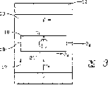
图3是图1所示三凸片轴颈轴承沿轴颈转动轴线截取的截面图,表示在轴颈转动期间润滑剂通过整个轴颈轴承的流动情况。Fig. 3 is a cross-sectional view of the three-lobed journal bearing shown in Fig. 1 taken along the axis of journal rotation, illustrating the flow of lubricant through the entire journal bearing during journal rotation.
图4A是根据本发明所述的一种改进的三凸片轴颈轴承的侧视截面图。Figure 4A is a side cross-sectional view of an improved three-lobed journal bearing according to the present invention.
图4B是图4A所示的改进的三凸片轴颈轴承的端部截面图。Figure 4B is an end cross-sectional view of the modified three-lobed journal bearing shown in Figure 4A.
图5A是根据本发明所述的改进的三凸片轴颈轴承的另一种实施例的侧视截面图。Figure 5A is a side cross-sectional view of another embodiment of an improved three-lobed journal bearing according to the present invention.
图5B是图5A所示的改进的三凸片轴颈轴承的侧视截面图。Figure 5B is a side cross-sectional view of the modified three-lobed journal bearing shown in Figure 5A.
详细说明 Detailed description
现在参照附图,在所有的图中相同的参照编号表示相应的部件,图1例示在转动机械如离心压缩机中使用的一种轴承结构10。图1所示的轴承结构10包括一个具有轴承内表面13的三凸片(lobe)轴颈轴承件12,用于支承一个围绕转动轴线15的可以转动的轴或轴颈14。虽然此处例示和说明的是三凸片轴承结构,但本发明可以用在任何类型的轴颈轴承上。轴承座箱(未示出)可以分开制造或作为轴承结构10整体的一部。通常,该三凸片轴颈轴承件12镶有例如用巴氏合金制成的轴承内衬(未示出)。上述类型的轴承已被用于承受径向负载和提供必需的动力特性以抑制由作用在轴或轴颈14上的各种激振力产生的振动。Referring now to the drawings, in which like reference numerals indicate corresponding parts throughout, Figure 1 illustrates a bearing arrangement 10 for use in a rotating machine such as a centrifugal compressor. The bearing structure 10 shown in FIG. 1 includes a three-lobe
如图2A和2B中所示,三凸片轴颈轴承件12包括多个由轴向槽16隔开的凸片。轴向槽16形成于轴颈轴承件12的轴承内表面13中。轴向槽16可以延伸至轴承的全长,或者槽16的长度可以小于轴颈轴承件12的全长。在轴向槽16的两端设有宽度小于槽16的宽度的泄放槽18。过去,已经改变过槽16和泄放槽18的尺寸以改变润滑剂端部流量,由此稍许改变轴承工作温度。As shown in FIGS. 2A and 2B , the three-lobed
润滑剂如合适的油通过多个开孔、小孔或孔20供应,这些孔过去设置在轴向槽16中。如可从图2A和2B中理解的,由于润滑剂供应孔在轴向槽16内所处的位置,通过该供应孔20供给的润滑剂在比轴承内表面13低得多的位置处供应给轴颈轴承件12。通常情况下,润滑剂通过外部泵(未示出)在中等压力下供应到轴承结构10上,或利用本技术中熟知的合适的润滑剂输送装置在大气压力下向轴承结构10供油。Lubricant, such as a suitable oil, is supplied through a plurality of openings, orifices or
图3是图1、2A和2B所示的先有技术三凸片轴颈轴承10的截面图,表示在轴颈转动期间润滑剂通过整个轴颈轴承的流动情况。应当理解,在轴14转动期间,润滑剂通过润滑剂供应孔20供应并进入轴向槽16。润滑剂而后由转动轴沿箭头17指示的转动方向被带走。由于转动速度和各种润滑剂的粘度,在轴承内表面13和轴颈14之间形成液体动压力,使得轴承内表面13和转动轴颈14由一层转动的热润滑剂隔开。该高的液体动压力被槽16所间断。同时由于轴承结构10内形成的磨擦而产生热量。当轴颈14继续转动时,从前一个凸片来的高温润滑剂端部流(θe)和侧部流(θs)进入轴向槽16并与新供应的润滑剂(θi)混合。混合的润滑剂(θm)绝大部分进入下一个凸片,其余一小部分则从轴向槽的开口端泄漏(θg)。通常,围绕轴颈14的转动的热润滑剂层的大部分将被带至下一凸片。人们已经发现,这样一种轴颈轴承设计在轴承结构10内产生高温润滑剂,这使润滑剂迅速氧化,因此缩短润滑剂使用寿命。同时,已经发现,这种轴承高温导致轴承表面产生清漆状的沉积物,最终会使轴承过早失效。FIG. 3 is a cross-sectional view of the prior art three-lobed journal bearing 10 shown in FIGS. 1, 2A and 2B, illustrating the flow of lubricant through the entire journal bearing during journal rotation. It will be appreciated that during rotation of the shaft 14 lubricant is supplied through the
根据本发明,下面将详细说明一种改进的轴承结构30,并将其示于图4A、4B、5A和5B中。According to the present invention, an improved
如图4A和4B所示,根据这种改进的轴承结构30的第一实施例,轴颈轴承件12如多凸片或三凸片轴颈轴承件支承一个可以围绕转动轴线(未示出)转动的轴或轴颈(未示出)。该轴颈轴承件有一内表面13和相对的第一和第二端部32和34,它们限定一个预定的轴承长度尺寸。轴颈轴承件12包括一个用于从轴承内部泄漏预定体积的润滑剂的装置。润滑剂泄漏机构包括在轴颈轴承件12的内表面13中形成的槽36。槽36具有相对的开口端部并沿轴承的长度方向延伸。槽36的两端可以倒角,或者槽36可以沿轴颈轴承12的整个长度连续延伸,如图4A中所示。As shown in FIGS. 4A and 4B, according to a first embodiment of this improved
通过轴颈轴承件12设置至少一个开孔、小孔或孔20,用于将润滑剂如合适的油供应到轴颈轴承件12的内表面13上。在优选实施例中,至少一个润滑剂供应孔20设置在沿轴承长度的大体中心处,且按图4B中箭头40所示的轴转动方向,位于槽36之后。该至少一个润滑剂供应孔20形成于轴承件的内表面,使得润滑剂直接供应在轴承件的内表面13上。At least one opening, aperture or
轴颈轴承件12也包括一个混合预定量润滑剂用的机构。该润滑剂混合机构包括一个在轴颈轴承件12的内表面13中形成的沟槽38。从图4B中可以清楚地看到,按箭头40所指示的轴颈转动方向,该槽38设置在上述至少一个润滑剂供应孔的后面。槽38有相对的封闭的端部并沿轴颈轴承件12的长度轴向延伸。
应当理解,在优选实施例中,多凸片轴颈轴承的每个凸片由第一槽36、至少一个润滑剂供应孔20和第二槽38隔开。It should be understood that in the preferred embodiment, each tab of the multi-lob journal bearing is separated by a
从图5A和5B中可清楚地看到本发明的另一实施例,其中混合一定体积的润滑剂用的机构如槽38包括至少一个润滑剂供应孔20,该孔穿过轴颈轴承件12且位于槽38的底部。Another embodiment of the present invention can be seen clearly from FIGS. 5A and 5B, wherein the mechanism for mixing a volume of lubricant, such as a
图4A和4B中所示的本发明实施例在工作过程中,润滑剂从位于内表面13处的至少一个供应孔20直接进入轴承内。进入的润滑剂的温度显著低于轴承结构30内转动的热润滑剂层的温度。在轴承内表面13处直接引入较冷的润滑剂具有使引入的润滑剂冲破围绕转动轴表面的热润滑剂层的效果,由此可使如前所述的热润滑剂从上一个凸片带到下一个凸片的量减少。更准确地说,在轴或轴颈转动期间,大多数热润滑剂由于沿轴转动方向的第一槽36的作用而从轴颈轴承件12中排出。其后,在轴颈轴承件12的内表面13上位于第一槽36之后、第二润滑剂混合槽38之前的位置处通过引入“冷”润滑剂引起的阻挡作用进一步促进了热润滑剂通过槽36从轴承向外泄漏。通过润滑剂供应孔的热润滑剂在第二槽38内与较冷的引入润滑剂混合。据以上所述,显然本发明能够降低轴承结构38的润滑剂工作温度,由此改善轴承性能并延长轴承寿命。During operation of the embodiment of the invention shown in Figures 4A and 4B, lubricant enters directly into the bearing from at least one
虽然本发明仅就一个优选实施例进行图示和说明,但应当认识到,可以进行修改和变化而不偏离下述权利要求书提出的发明。While the invention has been illustrated and described with respect to only one preferred embodiment, it should be appreciated that modifications and changes may be made without departing from the invention set forth in the following claims.
Claims (8)
Applications Claiming Priority (2)
| Application Number | Priority Date | Filing Date | Title |
|---|---|---|---|
| US08/290,454 US5456535A (en) | 1994-08-15 | 1994-08-15 | Journal bearing |
| US08/290,454 | 1994-08-15 |
Publications (1)
| Publication Number | Publication Date |
|---|---|
| CN1131981A true CN1131981A (en) | 1996-09-25 |
Family
ID=23116071
Family Applications (1)
| Application Number | Title | Priority Date | Filing Date |
|---|---|---|---|
| CN95190767A Pending CN1131981A (en) | 1994-08-15 | 1995-07-25 | journal bearing |
Country Status (6)
| Country | Link |
|---|---|
| US (2) | US5456535A (en) |
| EP (1) | EP0723633B1 (en) |
| JP (1) | JPH09504356A (en) |
| CN (1) | CN1131981A (en) |
| DE (1) | DE69521023T2 (en) |
| WO (1) | WO1996005443A1 (en) |
Cited By (4)
| Publication number | Priority date | Publication date | Assignee | Title |
|---|---|---|---|---|
| CN101539169B (en) * | 2008-03-19 | 2011-03-16 | 株式会社日立制作所 | Journal bearing device |
| CN101609286B (en) * | 2008-06-19 | 2012-01-11 | 京瓷美达株式会社 | Bearing structure, toner storage device and image forming apparatus provided with the bearing structure |
| CN105015518A (en) * | 2015-08-14 | 2015-11-04 | 安徽江淮汽车股份有限公司 | Self-lubricating brake pedal mechanism |
| CN108119548A (en) * | 2017-12-15 | 2018-06-05 | 重庆美的通用制冷设备有限公司 | Bearing bush and its sliding bearing assembly, compressor |
Families Citing this family (41)
| Publication number | Priority date | Publication date | Assignee | Title |
|---|---|---|---|---|
| EP0803657B1 (en) * | 1994-09-08 | 2003-01-15 | Kawasaki Jukogyo Kabushiki Kaisha | Reversing bearing device for double reversing propeller |
| US5951172A (en) * | 1995-10-13 | 1999-09-14 | Orion Corporation | Sleeve bearing lubrication |
| US6186278B1 (en) * | 1997-11-24 | 2001-02-13 | Mtd Products Inc | Bearing grease fitting and assembly |
| US6270259B1 (en) | 1999-09-09 | 2001-08-07 | Emerson Electric Co. | Powdered metal sintered bearing with improved oil flow polygonal interior bore |
| US6241392B1 (en) * | 2000-01-21 | 2001-06-05 | Coltec Industries Inc | Hybrid bearing |
| DE10030698A1 (en) * | 2000-06-23 | 2002-01-10 | Gleitlagertechnik Weissbacher | Process for lubricating and cooling a hydrodynamic plain bearing and device for carrying out this process |
| US6966700B2 (en) * | 2000-06-23 | 2005-11-22 | Gleitlagertechnik Weissbacher Gmbh | Hydrodynamic plain bearing and method of lubricating and cooling the bearing |
| JP4134541B2 (en) * | 2000-09-25 | 2008-08-20 | 株式会社ジェイテクト | Fluid bearing |
| JP2003004044A (en) * | 2001-06-25 | 2003-01-08 | Ishikawajima Harima Heavy Ind Co Ltd | Bearing body for journal bearings |
| US6810771B1 (en) * | 2001-08-27 | 2004-11-02 | Sonnax Industries, Inc. | Overdrive piston retainer |
| US6935849B2 (en) * | 2003-10-16 | 2005-08-30 | Honeywell International, Inc. | Grooved shaft member and associated turbocharger and method |
| JP4563036B2 (en) * | 2004-01-13 | 2010-10-13 | 三菱重工業株式会社 | Lubricating fluid discharge mechanism and bearing device |
| RU2399803C2 (en) * | 2004-06-15 | 2010-09-20 | Али ЭЛЬ-ШАФЕИ | Procedures for control of instability in hydro-dynamic bearings |
| US20050281499A1 (en) * | 2004-06-22 | 2005-12-22 | Wojtkowski Thomas Jr | Oil outlet for rolling mill oil film bearing |
| JP4664254B2 (en) * | 2006-08-29 | 2011-04-06 | 株式会社神戸製鋼所 | Compressor bearing |
| JP4867553B2 (en) * | 2006-09-28 | 2012-02-01 | トヨタ自動車株式会社 | Oil hole structure of connecting rod bearing |
| FR2916499B1 (en) * | 2007-05-24 | 2009-12-25 | Flender Graffenstaden | COIN SHELL WITH THIN SHELL. |
| JP5146338B2 (en) * | 2009-01-27 | 2013-02-20 | トヨタ自動車株式会社 | Bearing structure of internal combustion engine |
| JP5455491B2 (en) * | 2009-07-29 | 2014-03-26 | 大豊工業株式会社 | Bearing device |
| JP5436111B2 (en) * | 2009-09-16 | 2014-03-05 | 本田技研工業株式会社 | Lubricating oil supply structure |
| US8790066B2 (en) * | 2010-02-18 | 2014-07-29 | Honeywell International Inc. | Multi-lobe semi-floating journal bearing |
| JP2012002247A (en) * | 2010-06-14 | 2012-01-05 | Daido Metal Co Ltd | Half bearing |
| US8973551B2 (en) * | 2012-03-28 | 2015-03-10 | Cummins Inc. | Connecting rod lubrication apparatus |
| DE102012205950A1 (en) * | 2012-04-12 | 2013-10-17 | Bosch Mahle Turbo Systems Gmbh & Co. Kg | radial bearings |
| DE102012208966A1 (en) * | 2012-05-29 | 2013-12-05 | Continental Automotive Gmbh | Exhaust gas turbocharger with floating bush bearing |
| CN102765047B (en) * | 2012-08-07 | 2014-10-29 | 湖南大学 | Hydrostatic rotational supporting component for vertical shafting and grinding and polishing machine |
| US8556517B1 (en) * | 2012-09-19 | 2013-10-15 | Siemens Industry, Inc. | Bushing for oil film bearing |
| US9284976B2 (en) | 2013-03-09 | 2016-03-15 | Waukesha Bearings Corporation | Countershaft |
| US9279446B2 (en) * | 2013-03-09 | 2016-03-08 | Waukesha Bearings Corporation | Bearing with axial variation |
| WO2015153206A1 (en) | 2014-04-04 | 2015-10-08 | Borgwarner Inc. | Method and laser device for forming grooves in bearing surfaces, and bearings including such grooves |
| US9410572B2 (en) * | 2014-05-12 | 2016-08-09 | Lufkin Industries, Llc | Five-axial groove cylindrical journal bearing with pressure dams for bi-directional rotation |
| US9587672B1 (en) | 2015-08-11 | 2017-03-07 | Lufkin Industries, Llc | Adjustable offset pivot journal pad |
| ES2703824T3 (en) * | 2015-12-03 | 2019-03-12 | Flender Graffenstaden S A S | Hydrostatic bearing with hydrodynamic function |
| IL300968B2 (en) | 2016-05-17 | 2024-09-01 | El Shafei Aly | integrated bearing |
| DE102016224094A1 (en) | 2016-12-05 | 2018-06-07 | Bosch Mahle Turbo Systems Gmbh & Co. Kg | Bearing bush and associated charging device |
| DE102017213492A1 (en) * | 2017-08-03 | 2019-02-07 | Continental Automotive Gmbh | Floating bush bearing for an exhaust gas turbocharger |
| JP6961460B2 (en) | 2017-10-26 | 2021-11-05 | 大同メタル工業株式会社 | Connecting rod bearing for crank shaft of internal combustion engine |
| JP7013203B2 (en) * | 2017-10-26 | 2022-01-31 | 大同メタル工業株式会社 | Main bearing for crank shaft of internal combustion engine |
| DE102017125137A1 (en) * | 2017-10-26 | 2019-05-02 | Man Diesel & Turbo Se | Bushing of a turbocharger and turbocharger |
| CN111712326B (en) * | 2019-01-17 | 2023-02-03 | 德国莱歇公司 | Rolling rod module |
| CN114981548B (en) * | 2020-05-21 | 2024-12-06 | 株式会社Ihi | Bearings and superchargers |
Family Cites Families (17)
| Publication number | Priority date | Publication date | Assignee | Title |
|---|---|---|---|---|
| US2349690A (en) * | 1938-07-07 | 1944-05-23 | Bryant Grinder Corp | Bearing lubrication |
| US2449297A (en) * | 1941-03-26 | 1948-09-14 | James M Degnan | Automatic fluid pressure balancing system |
| NL152774A (en) * | 1950-01-24 | |||
| US2753229A (en) * | 1953-03-11 | 1956-07-03 | Inland Steel Co | Bearing construction |
| US2901297A (en) * | 1956-07-16 | 1959-08-25 | Gen Electric | Bearings |
| US3673743A (en) * | 1968-09-17 | 1972-07-04 | Dante S Giardini | Machine assembly |
| US3544180A (en) * | 1968-11-18 | 1970-12-01 | Gwilym Jones | Bearings |
| US3680932A (en) * | 1970-09-10 | 1972-08-01 | Westinghouse Electric Corp | Stable journal bearing |
| US4027928A (en) * | 1976-06-01 | 1977-06-07 | Turbodyne Corporation (Steam Turbine Div.) | Cooling and lubrication arrangement for water cooled bearings having self contained lubrication systems |
| US4159152A (en) * | 1977-10-11 | 1979-06-26 | Morgan Construction Company | Means for lubricating the roll neck/sleeve interface of an oil film bearing |
| JPS5544134A (en) * | 1978-09-22 | 1980-03-28 | Hitachi Ltd | Guide bearing |
| US4427309A (en) * | 1980-03-24 | 1984-01-24 | The Garrett Corporation | Turbocharger shaft bearing |
| US4402514A (en) * | 1981-09-10 | 1983-09-06 | General Electric Company | Fluid-cooled oil deflector |
| ATE25751T1 (en) | 1982-09-30 | 1987-03-15 | Hohenzollern Huettenverwalt | HYDROSTATIC BEARING. |
| US4764084A (en) * | 1987-11-23 | 1988-08-16 | Westinghouse Electric Corp. | Inlet flow guide for a low pressure turbine |
| US5145298A (en) * | 1989-09-11 | 1992-09-08 | Optima Industries, Inc. | High speed drill spindle |
| US5333955A (en) * | 1993-01-11 | 1994-08-02 | Papa George M | Automotive main bearing |
-
1994
- 1994-08-15 US US08/290,454 patent/US5456535A/en not_active Expired - Lifetime
-
1995
- 1995-04-12 US US08/421,345 patent/US5480234A/en not_active Expired - Lifetime
- 1995-07-25 EP EP95928339A patent/EP0723633B1/en not_active Expired - Lifetime
- 1995-07-25 JP JP8507432A patent/JPH09504356A/en active Pending
- 1995-07-25 WO PCT/US1995/009997 patent/WO1996005443A1/en not_active Ceased
- 1995-07-25 DE DE69521023T patent/DE69521023T2/en not_active Expired - Fee Related
- 1995-07-25 CN CN95190767A patent/CN1131981A/en active Pending
Cited By (6)
| Publication number | Priority date | Publication date | Assignee | Title |
|---|---|---|---|---|
| CN101539169B (en) * | 2008-03-19 | 2011-03-16 | 株式会社日立制作所 | Journal bearing device |
| CN101609286B (en) * | 2008-06-19 | 2012-01-11 | 京瓷美达株式会社 | Bearing structure, toner storage device and image forming apparatus provided with the bearing structure |
| CN105015518A (en) * | 2015-08-14 | 2015-11-04 | 安徽江淮汽车股份有限公司 | Self-lubricating brake pedal mechanism |
| CN105015518B (en) * | 2015-08-14 | 2019-02-19 | 安徽江淮汽车集团股份有限公司 | A kind of self-lubricating type brake treadle mechanism |
| CN108119548A (en) * | 2017-12-15 | 2018-06-05 | 重庆美的通用制冷设备有限公司 | Bearing bush and its sliding bearing assembly, compressor |
| CN108119548B (en) * | 2017-12-15 | 2020-06-05 | 重庆美的通用制冷设备有限公司 | Bearing bush, sliding bearing assembly with bearing bush and compressor |
Also Published As
| Publication number | Publication date |
|---|---|
| WO1996005443A1 (en) | 1996-02-22 |
| US5480234A (en) | 1996-01-02 |
| DE69521023D1 (en) | 2001-06-28 |
| EP0723633B1 (en) | 2001-05-23 |
| US5456535A (en) | 1995-10-10 |
| DE69521023T2 (en) | 2002-03-21 |
| EP0723633A1 (en) | 1996-07-31 |
| JPH09504356A (en) | 1997-04-28 |
Similar Documents
| Publication | Publication Date | Title |
|---|---|---|
| CN1131981A (en) | journal bearing | |
| KR0122313B1 (en) | Scroll compressor | |
| CA1146620A (en) | Bearing assembly for high speed shaft | |
| JP3984210B2 (en) | Oil damped rolling bearing | |
| KR101302761B1 (en) | Hydrodynamic axial bearing | |
| CN106536892A (en) | Bearing mechanism for turbocharger | |
| KR20110106875A (en) | Improved journal bearing design | |
| KR890004053B1 (en) | Crevice Seal Assembly | |
| US4936742A (en) | Water pump apparatus having lubricating oil circulation and axial thrust support | |
| CA1114851A (en) | Mechanical seal assembly | |
| JPH05256319A (en) | Radial bearing | |
| US5885066A (en) | Scroll compressor having oil bores formed through the crank shaft | |
| US6190148B1 (en) | Scroll-type fluid displacement device having sliding surface thrust bearing | |
| JP2004197890A (en) | Tilt pad bearing device | |
| JP4861315B2 (en) | Oil supply device | |
| KR910001182B1 (en) | Variable displacement compressor | |
| JP2001132737A (en) | Bearing device and turbine | |
| JP2008151239A (en) | Tilting pad type bearing | |
| JPH03163212A (en) | Dynamic pressure type fluid bearing device | |
| JP2008504497A (en) | Oil supply device | |
| US20230062651A1 (en) | Crankshaft bearing structure | |
| JP3824098B2 (en) | Floating bearing | |
| JP4346708B2 (en) | Turbine turbocharger | |
| KR840000204Y1 (en) | Reversing device for reciprocating engine | |
| JP4124510B2 (en) | Grooved plain bearing |
Legal Events
| Date | Code | Title | Description |
|---|---|---|---|
| C06 | Publication | ||
| PB01 | Publication | ||
| C10 | Entry into substantive examination | ||
| SE01 | Entry into force of request for substantive examination | ||
| C01 | Deemed withdrawal of patent application (patent law 1993) | ||
| WD01 | Invention patent application deemed withdrawn after publication |