Disclosure of Invention
The invention provides a composite impact drilling speed-up device, which comprises an outer cylinder, wherein an upper joint, a torsion impact assembly and a lower joint are axially and sequentially arranged in the outer cylinder;
the torsion impact assembly comprises a torsion hammer seat, an annular reversing seat and a torsion hammer head, the torsion hammer seat is fixedly embedded in the outer barrel body, and the torsion hammer head and the annular reversing seat are respectively rotatably installed in the outer barrel body;
the torsion hammer head is connected with and matched with the annular reversing seat, and rotates along with the annular reversing seat and reverses;
the torsion hammer head impacts the torsion hammer seat when rotating in a reciprocating manner and transmits impact force to the outer cylinder body;
the key points are as follows:
an axial impact assembly is arranged between the torsion impact assembly and the lower joint, and the torsion impact assembly is connected with the axial impact assembly through a connecting shaft;
the connecting shaft and the outer cylinder body are arranged on the same center line, the upstream end of the connecting shaft is fixedly connected with the torsion hammer head and rotates along with the torsion hammer head in a reciprocating and alternating manner, the downstream end of the connecting shaft extends towards the axial impact assembly, a middle drainage channel axially penetrates through the connecting shaft, a fluid inlet axially penetrates through the upper joint, and a reversing flow channel communicated with the fluid inlet and the middle drainage channel is arranged in the annular reversing seat;
the axial impact assembly comprises a shunting seat, a flow guide sleeve, an impact hammer head and an impact seat, the shunting seat is sleeved on the connecting shaft and is in spline fit with the connecting shaft, the shunting seat is in circumferential transmission connection with the connecting shaft and is in axial sliding connection with the connecting shaft, the upstream section of the shunting seat is in threaded fit with the outer cylinder body, and the shunting seat axially advances and retreats along with the reciprocating alternate rotation of the connecting shaft;
the flow guide sleeve is fixedly embedded in the outer cylinder body, and the flow guide sleeve and the outer cylinder body are arranged on the same central line;
the downstream section of the flow distribution seat extends into the flow guide sleeve and is in axial sliding fit with the flow guide sleeve, the impact hammer head is axially assembled in the flow guide sleeve in a sliding mode, the flow distribution seat is close to the torsion impact assembly, the impact hammer head is close to the lower joint, an impact flow channel axially penetrates through the impact hammer head, the downstream end of the connecting shaft extends into the impact flow channel, and the downstream end of the connecting shaft is axially assembled with the impact hammer head in a sliding mode;
the lower joint is arranged at the downstream end of the outer cylinder body, the impact seat is fixedly connected with the lower joint, the upstream section of the impact seat extends into the impact flow channel, the upstream section of the impact seat is axially assembled with the impact hammer head in a sliding manner, and a fluid outlet for communicating the impact flow channel with the outside is arranged on the impact seat and the lower joint in a penetrating manner;
a first filling area is formed between the shunting seat and the impact hammer head, and a second filling area is formed between the impact hammer head and the lower joint;
a first branch hole group penetrates through the wall of the connecting shaft;
a second branch hole group communicated with the impact flow channel and the second filling area is arranged between the impact hammer head and the impact seat;
a third branch hole group communicated with the first branch hole group penetrates through the branch seat;
a first discharge flow channel which can communicate the third branch hole group and the second filling area is arranged between the flow guide sleeve and the outer cylinder body;
a second discharge flow channel which can be communicated with the first filling area and the second filling area is arranged between the flow guide sleeve and the outer cylinder body;
the flow distribution seat ascends to ensure that the inlet of the first discharge flow channel and the third flow distribution hole group are staggered and closed, and the first flow distribution hole group is communicated with the first filling area; fluid is injected into the first filling area so as to push the impact hammer head to descend and impact the impact seat;
the flow dividing seat descends to enable an inlet of the first discharge flow channel to be communicated with the first flow dividing hole group through the third flow dividing hole group and to block communication between the first flow dividing hole group and the first filling area, fluid enters the second filling area and pushes the impact hammer head to ascend, and meanwhile fluid in the first filling area is pushed to enter the second filling area through the second discharge flow channel;
the second flow diversion orifice set is configured to direct fluid within the second packed region to the impingement flow passage and ultimately out through the fluid outlet.
Detailed Description
The present invention will be further described with reference to the following examples and the accompanying drawings.
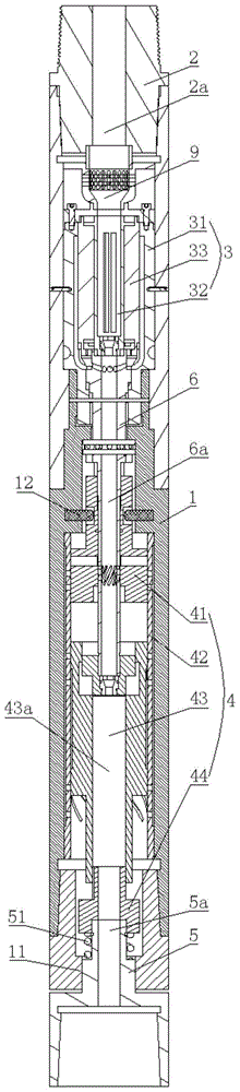
As shown in fig. 1 and 2, a composite impact drilling speed-increasing device comprises an outer cylinder 1, wherein an upper joint 2, a torsion impact assembly 3, an axial impact assembly 4 and a lower joint 5 are axially and sequentially arranged in the outer cylinder 1;
the torsion impact assembly 3 comprises a torsion hammer seat 31, an annular reversing seat 32 and a torsion hammer head 33, the torsion hammer seat 31 is fixedly embedded in the outer cylinder body 1, and the torsion hammer head 33 and the annular reversing seat 32 are respectively rotatably installed in the outer cylinder body 1;
the torque hammer 33 is connected with and matched with the annular reversing seat 32, and the torque hammer 33 rotates along with the annular reversing seat 32 and reverses;
the torsion hammer head 33 impacts the torsion hammer seat 31 when rotating in a reciprocating manner and transmits impact force to the outer cylinder 1;
a shunting seat 9 is further arranged between the upper joint 2 and the torsion impact assembly 3, and the shunting seat 9 is used for distributing fluid entering the torsion impact assembly 3. The fluid distribution scheme between the diversion seat 9 and the torque impact assembly 3, the assembling relationship between the torque hammer seat 31, the annular reversing seat 32 and the torque hammer head 33, the corresponding relationship among the flow passages, and how the three are rotationally matched under the action of the fluid in the prior art (for example, chinese patent No. 201721119860.2) are described, and are not repeated herein.
The torque impact assembly 3 and the axial impact assembly 4 are connected through a connecting shaft 6, the connecting shaft 6 and the outer cylinder 1 are arranged on the same center line, the upstream end of the connecting shaft 6 is fixedly connected with the torque hammer 33 and rotates along with the torque hammer in a reciprocating and alternating manner, the downstream end of the connecting shaft 6 extends towards the axial impact assembly 4, an intermediate drainage channel 6a axially penetrates through the connecting shaft 6, a fluid inlet 2a axially penetrates through the upper joint 2, and a reversing channel for communicating the fluid inlet 2a with the intermediate drainage channel 6a is arranged in the annular reversing seat 32;
the axial impact assembly 4 comprises a flow dividing seat 41, a flow guide sleeve 42, an impact hammer 43 and an impact seat 44, the flow dividing seat 41 is sleeved on the connecting shaft 6, the flow dividing seat 41 is in spline fit with the connecting shaft 6, the flow dividing seat 41 is in circumferential transmission connection with the connecting shaft 6 and is in axial sliding connection, the upstream section of the flow dividing seat 41 is in threaded fit with the outer cylinder 1, and the flow dividing seat 41 axially advances and retreats along with the reciprocating alternate rotation of the connecting shaft 6;
as a concrete screw-thread fit mode the upper reaches section outer wall of reposition of redundant personnel seat 41 is equipped with two sections at least helicla flutes, all the helicla flute winds reposition of redundant personnel seat 41 hoop evenly distributed correspond in the outer barrel 1 the helicla flute is equipped with guide post 12 respectively, guide post 12 radially sets up, the outer end of guide post 12 with outer barrel 1 inner wall is fixed, the inner of guide post 12 stretches into in the helicla flute.
The flow guide sleeve 42 is fixedly embedded in the outer cylinder body 1, and the flow guide sleeve 42 and the outer cylinder body 1 are arranged on the same central line;
the downstream section of the flow dividing seat 41 extends into the flow guide sleeve 42 and is in axial sliding fit with the flow guide sleeve 42, the impact hammer 43 is axially assembled in the flow guide sleeve 42 in a sliding manner, the flow dividing seat 41 is close to the torsion impact assembly 3, the impact hammer 43 is close to the lower joint 5, an impact flow passage 43a axially penetrates through the impact hammer 43, the downstream end of the connecting shaft 6 extends into the impact flow passage 43a, and the downstream end of the connecting shaft 6 is axially assembled with the impact hammer 43 in a sliding manner;
in order to reduce the friction between the impact hammer 43 and the flow guide sleeve 42, the outer wall of the upstream end of the impact hammer 43 protrudes radially outwards, the outer wall of the downstream end of the impact hammer 43 protrudes radially outwards, and the outer wall of the upstream end and the outer wall of the downstream end of the impact hammer 43 are axially and slidably assembled with the flow guide sleeve 42.
The lower end of the outer barrel 1 is retracted inwards to form a support ring 11, the lower joint 5 is axially assembled in the support ring 11 in a sliding mode, the lower joint 5 is in spline fit with the support ring 11, the impact seat 44 is fixedly connected with the lower joint 5, the lower joint 5 is further movably sleeved with a return spring 51, one end of the return spring 51 is supported against the impact seat 44, and the other end of the return spring 51 is supported against the support ring 11;
the impact seat 44 comprises a pressure-bearing section 441 and an insertion section 442 which are fixedly connected with each other, the insertion section 442 extends in an upstream direction and extends into the impact flow channel 43a, the insertion section 442 is axially assembled with the impact hammer head 43 in a sliding manner, the outer wall of the insertion section 442 is axially provided with a plurality of flow guide grooves, the plurality of flow guide grooves form the second flow distribution hole group 8b, and the impact hammer head 43 impacts the pressure-bearing section 441 in a downward direction;
a fluid outlet 5a for communicating the impact flow passage 43a with the outside is formed through the impact seat 44 and the lower joint 5;
a first filling area 7a is formed between the flow dividing seat 41 and the impact hammer head 43, and a second filling area 7b is formed between the impact hammer head 43 and the lower joint 5;
a first branch hole group 8a penetrates through the wall of the connecting shaft 6;
a second branch hole group 8b communicating the impact flow channel 43a and the second filling area 7b is arranged between the impact hammer 43 and the impact seat 44;
a third branch hole group 8c that can communicate with the first branch hole group 8a is formed through the branch seat 41;
a first discharge flow channel which can communicate the third flow dividing hole group 8c and the second filling area 7b is arranged between the flow guide sleeve 42 and the outer cylinder 1;
a second discharge flow passage which can communicate the first filling area 7a and the second filling area 7b is arranged between the flow guide sleeve 42 and the outer cylinder 1;
as a specific embodiment, the first discharge flow passage and the second discharge flow passage may be provided in the following manner:
the outer walls of two ends of the flow guide sleeve 42 are respectively fixed and sealed with the inner wall of the outer cylinder 1, and an overflowing interlayer 1a is formed between the middle part of the outer wall of the flow guide sleeve 42 and the inner wall of the outer cylinder 1; a fourth branch hole group 8d, a fifth branch hole group 8e and a sixth branch hole group 8f are sequentially arranged on the wall of the flow guide sleeve 42 in the axial direction, the fourth branch hole group 8d, the fifth branch hole group 8e and the sixth branch hole group 8f respectively communicate the interior of the flow guide sleeve 42 with the flow passing interlayer 1a, the fourth branch hole group 8d is close to the flow guide seat 41, and the sixth branch hole group 8f is close to the impact seat 44;
the flow-passing interlayer 1a between the fourth flow distribution hole group 8d and the sixth flow distribution hole group 8f forms the first discharge flow channel, and the flow-passing interlayer 1a between the fifth flow distribution hole group 8e and the sixth flow distribution hole group 8f forms the second discharge flow channel.
First reposition of redundant personnel punch combination 8a has n first reposition of redundant personnel holes, first reposition of redundant personnel hole radially runs through reposition of redundant personnel seat 41, third reposition of redundant personnel punch combination 8c has n third reposition of redundant personnel holes, fourth reposition of redundant personnel punch combination 8d has n fourth reposition of redundant personnel holes, the inner of third reposition of redundant personnel hole corresponds one first reposition of redundant personnel hole the outer end of third reposition of redundant personnel hole corresponds one fourth reposition of redundant personnel hole, first reposition of redundant personnel hole with fourth reposition of redundant personnel hole all follows the trend setting of helicla flute.
The flow dividing seat 41 moves upward, so that the inlet of the first discharge flow channel and the third flow dividing hole group 8c are staggered and closed, and the first flow dividing hole group 8a is communicated with the first filling area 7 a; fluid is injected into the first filling zone 7a so as to push the impact ram 43 downwards and impact the impact seat 44;
the flow dividing seat 41 moves downwards, so that the inlet of the first discharge flow channel is communicated with the first flow dividing hole group 8a through the third flow dividing hole group 8c, the communication between the first flow dividing hole group 8a and the first filling area 7a is blocked, fluid enters the second filling area 7b and pushes the impact hammer head 43 to move upwards, and meanwhile, the fluid in the first filling area 7a is pushed to enter the second filling area 7b through the second discharge flow channel;
the second set of branch holes 8b is used to guide the fluid in the second packed region 7b to the impulse flow path 43a and finally to be discharged through the fluid outlet 5 a.
Has the advantages that: by adopting the composite impact drilling speed-increasing device provided by the invention, circumferential impact is transmitted to the lower joint through the shell, axial impact is transmitted to the lower joint through the impact seat, the lower joint is connected with the drill bit, so that composite impact on the drill bit is formed, the axial impact is controlled by the circumferential impact to change, and the optimal rock breaking track which is adaptive to different conditions can be fitted by coordinating the impact time and the impact frequency of the circumferential impact and the axial impact, so that the speed-increasing effect of the tool is exerted to the maximum extent. The problem that the action time phase of axial impact and axial impact cannot be controlled by the existing composite impact tool is solved, so that the problems of stick slip, dragging pressure and the like in the drilling process of a deep well hard formation can be effectively solved, the drilling speed is increased, and the well quality and the steering precision are improved.
Finally, it should be noted that the above-mentioned description is only a preferred embodiment of the present invention, and those skilled in the art can make various similar representations without departing from the spirit and scope of the present invention.