Resistance increasing device and well completion structure for improving axial packing effect of continuous packing body along shaft
Technical Field
The invention belongs to the technical field of oil and gas well exploitation, and relates to a resistance increasing device capable of improving the axial packing effect of a continuous packing body in a shaft along the shaft, a method capable of improving the axial packing effect of the continuous packing body in the shaft along the shaft, and a well completion structure capable of improving the axial packing effect of the continuous packing body in the shaft along the shaft.
Background
In the oil and gas well exploitation technical field, the shaft of the oil and gas well generally penetrates through a plurality of sections of stratums, because the permeability of each section of stratum is usually inconsistent, and the viscosity of the stratum water is far less than that of the crude oil to be exploited, under the same bottom hole pressure difference, a large amount of stratum water is often produced from the local stratum with high permeability. The common water control method is to put a flow control pipe column (or a water control pipe column) with balanced flow into the well for water control. When the flow control pipe column is arranged in the shaft for controlling water and increasing oil, the formation water axially flows in the shaft annulus along the shaft annulus, so that the flow control of the flow control pipe column is ineffective. By sealing the shaft annulus, the production of formation water is controlled, and the channeling of the formation water in the shaft annulus is reduced, so that the method is an effective method for improving the crude oil recovery ratio. The existing method for realizing water control by packing shaft annulus mainly comprises two modes of expanding packer water control and continuous packing body water control.
The expansion packer is applied to a certain extent due to simple structure and low cost. However, this device has the following disadvantages when in use: in the first aspect, since the diameter of the device is larger than the diameter of the central pipe string (or close to the diameter of the well bore), the phenomenon that a pipe string formed by connecting a plurality of central pipe strings is blocked when the well is lowered is very easy to occur. To solve the downhole choke problem, it is necessary to reduce the number of expansion packers placed on the string, for example one per 50-100 meter interval, to isolate the wellbore into multiple separate isolated units of 50-100 meters in length. However, inside each separation unit, the wellbore annulus is still connected, and the problem of cross flow still exists, which leads to the oil production of the unit being not optimal; in extreme cases, if there is a large water outlet zone inside the separation unit (e.g. by a crack communicating with the ground bottom water), the oil recovery of the separation unit will become even lower. In the second aspect, the expansion packer is usually a prefabricated member and cannot perfectly adapt to complex well conditions such as inconsistent well diameters, non-centered central pipe columns, uneven well wall surfaces and the like, so that formation water channeling among different separation units cannot be thoroughly avoided. In the third aspect, the packer can be tightly attached to the well wall and can not be pulled out after being completely expanded when meeting the liquid. And a gap is reserved between the resistance increasing device and the well wall, so that the resistance increasing device can be pulled out.
The continuous packer water control is a new oil-gas well water control method in recent years. Referring to Chinese invention patents CN2009102507912, CN2014100135988, CN2019100846588, CN2019104892759 and the like, the basic principle of the method is to fill packing particles into a shaft to form a continuous packing body, micro-channels in the continuous packing body formed by micro-pores among the packing particles have a channeling-preventing effect on produced fluid, so that the production of formation water is reduced, and the practical application requirements under various well conditions (such as irregular well diameter, leakage in the shaft, deformation, cement ring channeling, annular space outside an old screen pipe, annular space outside a perforated pipe and the like) can be met. However, there are still some disadvantages in the application of this method: on one hand, because the continuous packer is bound to have a micro-channel for oil gas to pass through, in order to ensure the smooth production of the oil gas, the resistance of the micro-channel to the flow of produced liquid is not too small, so as to ensure the flow of the produced liquid; on the other hand, because the mobility of water is much higher than that of oil, for a scene that the interval between each section of stratum is small (for example, 2-5 meters), the produced water of a high-water stratum of a local well section in the shaft still flows to the adjacent stratum structure well section along the shaft annular space through the micro-channel in the continuous packer body when the flowing water quantity is large. That is, there is still a significant cross-flow of produced water in the wellbore, which may not optimize oil recovery.
Specifically, the conventional range of use of packer particles is 16-100 mesh (particle size range 0.15-1.18mm), corresponding to continuous packers with a permeability of 20D-300D, even 20D permeability is still high relative to the formation permeability. For example, a 6-in multi-layer vertical well is run in a 3-1/2in water control screen, filled with continuous packer particles with a permeability of 40D, and a 2 meter long continuous packer annulus (i.e., the continuous packer corresponding to the blind section between two screens) has a flow rate of 29 square/day at a production pressure of 1 MPa. And a flow control screen pipe of 5-1/2in is arranged in a certain horizontal well of 8-1/2in, continuous packer particles with the permeability of 20D are filled, and the flow rate of the continuous packer rings of 2 meters in length is 45 square/day under the production pressure difference of 1 MPa. Therefore, even if the continuous packer is used for controlling water, the interlayer axial channeling flow in the annular space of the well casing is still large, and the packing effect is necessary to be further improved.
Disclosure of Invention
The invention aims to overcome the defects of the prior art, and provides a resistance increasing device and a resistance increasing device which have the advantages of simple structure, convenience in operation, high reliability, good effect of limiting the flow of channeling, no influence on the filling of continuous packer particles in a production section and capability of improving the axial packing effect of a continuous packer in a shaft along the shaft, and a well completion structure capable of improving the axial packing effect of the continuous packer in the shaft along the shaft.
In order to achieve the purpose, the invention provides the following technical scheme:
a can improve the increasing choke of the axial packing effect of continuous packing body in the pit shaft, the said increasing choke is the cylindrical structure wholly; a central mounting hole for mounting a central pipe column is formed in the axial center of the resistance increasing device; one or more filling channels which are consistent with the axial direction of the cylinder are arranged inside and/or outside the resistor-increasing device, and the sum of effective flow areas of the filling channels is 1/20-1/2 of the cross section area of the cylinder.
Further, the filling channel of resistance increase ware is a plurality of, a plurality of filling channel is based on the axis of cylinder is circumference symmetric distribution.
Furthermore, two ends of the resistor-increasing device are respectively provided with an annular groove communicated with each filling channel, and the annular grooves at the two ends are consistent in size and position relative to the axis of the cylinder; the effective flow guide area of the annular groove is not smaller than the flow area of the single filling channel.
Further, the cross-sectional shape of the filling channel inside the resistance increasing device is one or more of a circle, an ellipse, a sector and a fillet sector.
Further, the cross-sectional shape of a filling channel on the outer side of the choke plug is one or more of a semicircle, a sector and a fillet/chamfer sector, and the outer side surface of the filling channel is communicated with the annulus of the shaft.
In order to achieve the purpose, the invention also provides the following technical scheme:
the resistance-increasing device capable of improving the axial blocking effect of the continuous blocking body in the shaft comprises the resistance-increasing device and the center pipe column, wherein the center pipe column penetrates through the center mounting hole of the resistance-increasing device and is fixedly connected with the resistance-increasing device.
Furthermore, the resistance increasing device and the central pipe column are connected and fixed in one or more modes of welding, bolt fixing or clamping piece fixing.
Further, the central pipe column is a short blind pipe;
furthermore, flow control filter pipe strings are installed at two ends of the short blind pipe.
In order to achieve the purpose, the invention provides the following technical scheme:
a well completion structure capable of improving axial packing effect of a continuous packing body in a shaft comprises a plurality of center pipe columns which are arranged in the shaft in an end-to-end mode, wherein the continuous packing body is arranged in an annular space between the center pipe columns and the wall of the shaft, and the choke adding device is arranged on one or more center pipe columns.
In order to achieve the purpose, the invention provides the following technical scheme:
a well completion structure capable of improving the axial packing effect of a continuous packing body in a shaft along the shaft comprises a plurality of center pipe columns which are arranged in the shaft in an end-to-end mode, wherein the continuous packing body is arranged in an annular space between the center pipe columns and the wall of the shaft, and one or more center pipe columns are the resistance-increasing devices.
The invention relates to a choke adding device and a well completion structure capable of improving the axial packing effect of a continuous packing body along a shaft. Secondly, because the whole annular space is filled with the continuous packer and no space is provided for storing the silt generated by the earthworm holes, the earthworm holes cannot be formed at the two ends of the packer, and the problems of well wall collapse, silt migration and the like cannot be caused. Thirdly, the flow guide grooves are formed in the two ends of the resistance increasing devices, when the resistance increasing devices are used as standard parts in series, the resistance increasing devices can be installed on the central pipe column in series according to actual requirements on site, and the filling channels of the resistance increasing devices are not required to be aligned, so that the field assembly and the use are very convenient, the field installation efficiency can be improved, and the channeling flow of the stratum produced water in a shaft can be more accurately limited.
Drawings
FIG. 1 is a front sectional view of a choke plug for improving the axial packing effect of a continuous packing body along a shaft in an embodiment of the invention;
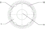
FIG. 2 is a left side view of a choke plug for increasing the axial packing effect of a continuous packer along a wellbore in an embodiment of the invention;
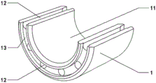
FIG. 3 is a schematic diagram of the overall structure of a choke-increasing device for improving the axial packing effect of a continuous packing body along a shaft in the embodiment of the invention;
FIG. 4 is a sectional view of the overall structure of a choke-increasing device for increasing the axial packing effect of a continuous packing body along a shaft in the embodiment of the invention;
FIG. 5 is a front sectional view of another embodiment of the resistance increasing device for increasing the axial packing effect of a continuous packing body along a wellbore;
FIG. 6 is a left side view of another embodiment of the choke plug of the present invention for increasing the axial packing effect of the continuous packing along the wellbore;
FIG. 7 is a schematic diagram of the overall structure of another choke-increasing device for improving the axial packing effect of a continuous packing body along a shaft in the embodiment of the invention;
FIG. 8 is a sectional view of the overall construction of another choke-increasing device for increasing the axial packing effect of a continuous packing along a wellbore in an embodiment of the present invention;
fig. 9 is a schematic overall structure diagram of a specific application of the resistance increasing device in the well bore, wherein the resistance increasing device is used for improving the axial packing effect of the continuous packing body along the well bore in the embodiment of the invention.
Fig. 10 is a schematic view of the overall structure of a conventional injection-production system according to an embodiment of the present invention;
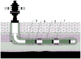
fig. 11 is a schematic diagram of the overall structure of an injection-production system employing a resistance-increasing device for improving the axial packing effect of a continuous packing body along a wellbore in an embodiment of the present invention.
Detailed Description
The following further describes an embodiment of a choke-increasing device and a well completion structure for improving the axial packing effect of a continuous packing body along a wellbore according to the present invention with reference to fig. 1 to 9. It should be noted that the drawings in the specification are only used for visually showing the whole or partial specific features of the technical scheme disclosed in the embodiment, and the proportion or the dimensional structure is not drawn according to the actual product, so that the technical scheme disclosed in the embodiment cannot be limited; the choke-increasing device and the well completion structure for improving the axial packing effect of the continuous packing body along the shaft of the well are not limited to the description of the following embodiments.
Example 1:
the embodiment provides a resistance increasing device capable of improving the axial packing effect of a continuous packing body in a shaft.
As shown in fig. 1 to 8, the resistance increasing device 1 is integrally in a cylindrical structure or an approximately cylindrical structure, and the shape structure is designed to facilitate the resistance increasing device 1 to be put into a shaft 2 after being assembled with a central pipe string as a sleeve structure. The axial center position of the resistance increasing device 1 is provided with a central mounting hole 11 (namely, the central mounting hole 11 of the sleeve structure) for mounting a central pipe column, and one or more filling channels 12 consistent with the axial direction are/is arranged inside and/or outside the resistance increasing device 1; the sum of the effective flow areas of the filling channels 12 is 1/20-1/2 of the cross-sectional area of the cylinder. The effective flow area of the filling channel 12 refers to the cross-sectional area of the filling channel 12. Specifically, in the stage of filling the packing particles, the packing fluid carrying the packing particles mainly flows through the filling channel 12 of the choke 1 and the outer annular space thereof, and the packing particles are conveyed to the deep part of the shaft 2 and gradually accumulated from the deep part of the shaft 2 to the shallow part to form a continuous packing body; during the production phase, the production fluid in the annular space of the shaft 2 is mainly subjected to cross flow through the outer annular space of the choke 1 and the filling channel 12 of the choke 1.
Specifically, the number of the filling channels 12 is at least 1, and may be plural. When the filling channel 12 of the resistor 1 is plural, the plural filling channels 12 are circumferentially symmetrically distributed based on the axis of the cylinder. The resistor 1 may be provided with only the inner filling channel 12 or the outer filling channel 12, but it is also possible to provide both filling channels 12.
As shown in fig. 1-4, the filling channel 12 of the resistor 1 is arranged inside, and the cross section is in the shape of one or more of a circle, an ellipse, a sector and a circular-arc sector; of course, other similar shapes are possible, but a circular or fan-shaped structure is adopted, so that the processing is convenient, and the resistance to the filling liquid is small.
As shown in fig. 5-8, the filling channel 12 of the choke plug 1 is arranged on the outer side, the cross section is in the shape of one or more of a semicircle, a sector, a fillet/chamfer sector, and the outer side surface of the filling channel 12 is communicated with the annular space of the shaft 2. The fillet/chamfer sector is that two corners close to the axis are in a sector shape, and two corners far away from the axis are in a chamfer shape, so that the resistance to filling liquid can be reduced by the two fillets on the inner side, and the probability of blockage caused by the chamfer on the outer side is in a cambered surface shape during well descending can be reduced. The communication means that the outer side surface of the filling channel 12 is an open structure and is connected with the shaft 2 annulus into a whole, and after filling is finished, an integrated continuous packer can be formed.
Preferably, the resistance-increasing device 1 is provided with an annular groove 13 at each end, which is communicated with each filling channel 12, and the annular grooves 13 at the two ends have the same size (including the diameter of the ring, the width and the depth of the groove) and the same position relative to the axis of the cylinder (the circle center of the ring is located on the axis). The annular groove 13 is provided for the purpose of selectively determining, on site, a corresponding number of resistor boosters 1 to be used in series, according to the resistance value to be generated, when the prefabricated resistor boosters 1 are used as standard parts. When two or more of the resistance increasing devices 1 are used in series, if the annular groove 13 is not provided, the filling channel 12 of the resistance increasing device 1 needs to be completely aligned and then used, otherwise, the filling channel 12 is blocked and filling fluid cannot be injected into the well bore 2. By arranging the annular grooves 13, the annular grooves 13 of two adjacent resistance increasing devices 1 can form diversion trenches, so that the filling channels 12 of two adjacent resistance increasing devices 1 are communicated. In order to ensure the communication effect, the effective flow guiding area of the annular groove 13 should be no less than the flow area of the single filling channel 12. Specifically, the number of the annular grooves 13 may be one or more, and is determined according to the number and arrangement of the filling channels 12. If the filling channel 12 is arranged in two turns, two annular grooves 13 with different diameters need to be provided. By arranging the annular groove 13, when a user installs a plurality of resistance increasing devices 1 on a central pipe column (such as a blind pipe), the alignment problem of a flow guide channel is not considered, so that the working efficiency can be improved; meanwhile, through the free combination of the resistance increasing devices 1, the additionally increased resistance value of the produced fluid in the well shaft 2 after the production can be flexibly and accurately set.
If the filling channel 12 is provided only on the outside, as a simplified structure, the annular groove 13 may not be provided, and the annular space outside the choke body 1 is used as a flow guide channel. This embodiment should be considered as an equivalent technical solution to the present embodiment.
Example 2:
the embodiment provides a resistance increasing device capable of improving the axial packing effect of a continuous packing body in a shaft 2.
The resistance increasing device comprises the resistance increasing device 1 and a center pipe column according to embodiment 1, wherein the center pipe column penetrates through a center mounting hole 11 of the resistance increasing device 1 and is fixedly connected with the resistance increasing device 1. Specifically, the resistance increasing device 1 and the central pipe column are connected and fixed through one or more of welding, bolt fixing or clamping piece fixing modes. As an alternative embodiment, the central pipe column is a short blind pipe; of course, the centre string may also be a screen or another type of string, for example with the choke 1 arranged at one or both ends of the screen.
The technical scheme of the embodiment aims to enable the resistance increasing device 1 and the central pipe column to be standard components and to be a standardized resistance increasing device, so that the resistance increasing device can be directly used as a central pipe column with a resistance increasing function for downhole construction without field assembly, and construction operation is facilitated.
Example 3:
this embodiment provides a specific application of the resistor/resistor increasing device described in embodiment 1 or 2.
(1) Splicing the resistance increasing device 1 with a central pipe column to form a resistance increasing device, or directly splicing the resistance increasing device with other central pipe columns such as sieve pipes 3 and the like into a pipe string according to a preset number and position by adopting a prefabricated resistance increasing device, and then putting the pipe string into a shaft 2;
(2) filling liquid carrying packing particles into the shaft 2 through the annulus of the shaft 2; as shown in fig. 9, the packing fluid carries packing particles to gradually accumulate in the annulus of the shaft 2 from inside to outside to form a continuous packing body 4; the continuous packer 4 is filled with a filling channel 12 of the resistor/resistor increasing device and an outer annular empty area of the resistor/resistor increasing device at the same time;
(3) putting into production; the production fluid and the produced water in the annulus of the wellbore 2 are subjected to a cross-flow in the annulus, and when passing through the zone where the resistor/resistor increasing device is located, the resistance received is greater than that in the zone where the resistor/resistor increasing device is not located, due to the smaller effective flow area of the filling channel 12, and thus the cross-flow rate is smaller.
For example, a flow control screen pipe of 5-1/2in is put into a horizontal well of 8-1/2in, continuous packer particles with the permeability of 20D are filled, and the continuous packer channeling rate corresponding to a dead zone between two screen pipes is 45 square/day under the production pressure difference of 1 MPa. After the flow increasing device disclosed by the invention is applied to the adjacent well of the 8-1/2in horizontal well, the channeling rate of a continuous packer corresponding to a blind section between two screen pipes is 15 square/day.
Example 4:
this embodiment shows another specific application of the resistor/resistor increasing device described in embodiment 1 or 2.
As shown in fig. 10, is an injection-production system comprising a water injection well M1 and a production well M2. It can be seen from the figure that, due to the higher permeability of the formation at C, more driving fluid (usually formation water, indicated by a black bold line in the figure) injected into the water injection well M1 enters the production well M2 through the formation at C, which results in a higher water content in the production fluid of the production well M2, and in that the driving fluid at A, B, D, E in the wellbore partially flows into C due to the channeling of the driving fluid in the wellbore, resulting in a lower driving fluid pressure in the formation at A, B, D, E and a lower oil recovery efficiency. Therefore, the working efficiency of the injection-production system cannot be optimized.
As shown in fig. 11, a completion is formed in the injection well M1 according to the method described in example 3. After the injection, the channeling of the driving liquid injected into the water injection well M1 through the central column in the annular space of the shaft 2 is reduced, the driving liquid in the annular space at A, B, D, E cannot (or less) crossflow to the annular space at C, so that the driving liquid cannot enter the stratum at C, and as a result, the content of water in the production liquid in the stratum at C in the oil production well M2 is reduced, and the driving liquid pressure in the stratum at A, B, D, E is increased, so that the oil displacement effect is enhanced, the oil production amount of the corresponding stratum is increased, and the oil recovery rate of the injection and production system is optimized.
Example 5:
the embodiment provides a well completion structure capable of improving axial packing effect of a continuous packing body in a shaft, which comprises a plurality of center pipe columns arranged in the shaft in an end-to-end mode, wherein flow control filter pipe strings are arranged at two ends of each center pipe column 4. And a continuous packer is arranged in an annular space between the central pipe column and the well wall of the shaft. The difference from the prior art is that: in the completion configuration, the choke plug of embodiment 1 is on the one or more of the central strings; alternatively, the one or more centerpipe strings are the friction enhancing devices of embodiment 2. It should be noted that the well completion structure provided in this embodiment is applicable not only to a production well, but also to a water injection well.
In this embodiment, through setting up the resistance-increasing device that has less area of overflowing/resistance-increasing, resistance when can increase the production fluid drunkenness in the pit shaft annular space to reduce the drunkenness of producing formation produced water in the pit shaft annular space, improve the whole oil recovery rate of oil well.
The foregoing is a more detailed description of the invention in connection with specific preferred embodiments and it is not intended that the invention be limited to these specific details. For those skilled in the art to which the invention pertains, several simple deductions or substitutions can be made without departing from the spirit of the invention, and all shall be considered as belonging to the protection scope of the invention.