CN113236334A - Full-servo positive and negative linkage air door and control method - Google Patents
Full-servo positive and negative linkage air door and control method Download PDFInfo
- Publication number
- CN113236334A CN113236334A CN202110412847.0A CN202110412847A CN113236334A CN 113236334 A CN113236334 A CN 113236334A CN 202110412847 A CN202110412847 A CN 202110412847A CN 113236334 A CN113236334 A CN 113236334A
- Authority
- CN
- China
- Prior art keywords
- air
- valve
- way
- door
- pulled
- Prior art date
- Legal status (The legal status is an assumption and is not a legal conclusion. Google has not performed a legal analysis and makes no representation as to the accuracy of the status listed.)
- Pending
Links
- 238000000034 method Methods 0.000 title claims abstract description 11
- 229910000831 Steel Inorganic materials 0.000 claims description 9
- 239000010959 steel Substances 0.000 claims description 9
- 238000009423 ventilation Methods 0.000 claims description 7
- 229920002396 Polyurea Polymers 0.000 claims description 4
- 238000001914 filtration Methods 0.000 claims description 3
- 230000008569 process Effects 0.000 claims description 2
- 239000003245 coal Substances 0.000 description 3
- 239000000463 material Substances 0.000 description 2
- 230000004048 modification Effects 0.000 description 2
- 238000012986 modification Methods 0.000 description 2
- RNFJDJUURJAICM-UHFFFAOYSA-N 2,2,4,4,6,6-hexaphenoxy-1,3,5-triaza-2$l^{5},4$l^{5},6$l^{5}-triphosphacyclohexa-1,3,5-triene Chemical compound N=1P(OC=2C=CC=CC=2)(OC=2C=CC=CC=2)=NP(OC=2C=CC=CC=2)(OC=2C=CC=CC=2)=NP=1(OC=1C=CC=CC=1)OC1=CC=CC=C1 RNFJDJUURJAICM-UHFFFAOYSA-N 0.000 description 1
- 230000008859 change Effects 0.000 description 1
- 238000005260 corrosion Methods 0.000 description 1
- 230000007797 corrosion Effects 0.000 description 1
- 239000003063 flame retardant Substances 0.000 description 1
- 238000004519 manufacturing process Methods 0.000 description 1
- 239000003595 mist Substances 0.000 description 1
- 238000003825 pressing Methods 0.000 description 1
Images



Classifications
-
- E—FIXED CONSTRUCTIONS
- E21—EARTH OR ROCK DRILLING; MINING
- E21F—SAFETY DEVICES, TRANSPORT, FILLING-UP, RESCUE, VENTILATION, OR DRAINING IN OR OF MINES OR TUNNELS
- E21F1/00—Ventilation of mines or tunnels; Distribution of ventilating currents
- E21F1/10—Air doors
-
- E—FIXED CONSTRUCTIONS
- E05—LOCKS; KEYS; WINDOW OR DOOR FITTINGS; SAFES
- E05B—LOCKS; ACCESSORIES THEREFOR; HANDCUFFS
- E05B51/00—Operating or controlling locks or other fastening devices by other non-mechanical means
- E05B51/02—Operating or controlling locks or other fastening devices by other non-mechanical means by pneumatic or hydraulic means
-
- E—FIXED CONSTRUCTIONS
- E05—LOCKS; KEYS; WINDOW OR DOOR FITTINGS; SAFES
- E05F—DEVICES FOR MOVING WINGS INTO OPEN OR CLOSED POSITION; CHECKS FOR WINGS; WING FITTINGS NOT OTHERWISE PROVIDED FOR, CONCERNED WITH THE FUNCTIONING OF THE WING
- E05F15/00—Power-operated mechanisms for wings
- E05F15/50—Power-operated mechanisms for wings using fluid-pressure actuators
- E05F15/53—Power-operated mechanisms for wings using fluid-pressure actuators for swinging wings
-
- E—FIXED CONSTRUCTIONS
- E21—EARTH OR ROCK DRILLING; MINING
- E21F—SAFETY DEVICES, TRANSPORT, FILLING-UP, RESCUE, VENTILATION, OR DRAINING IN OR OF MINES OR TUNNELS
- E21F1/00—Ventilation of mines or tunnels; Distribution of ventilating currents
- E21F1/10—Air doors
- E21F1/12—Devices for automatically opening air doors
-
- F—MECHANICAL ENGINEERING; LIGHTING; HEATING; WEAPONS; BLASTING
- F15—FLUID-PRESSURE ACTUATORS; HYDRAULICS OR PNEUMATICS IN GENERAL
- F15B—SYSTEMS ACTING BY MEANS OF FLUIDS IN GENERAL; FLUID-PRESSURE ACTUATORS, e.g. SERVOMOTORS; DETAILS OF FLUID-PRESSURE SYSTEMS, NOT OTHERWISE PROVIDED FOR
- F15B11/00—Servomotor systems without provision for follow-up action; Circuits therefor
- F15B11/16—Servomotor systems without provision for follow-up action; Circuits therefor with two or more servomotors
-
- F—MECHANICAL ENGINEERING; LIGHTING; HEATING; WEAPONS; BLASTING
- F15—FLUID-PRESSURE ACTUATORS; HYDRAULICS OR PNEUMATICS IN GENERAL
- F15B—SYSTEMS ACTING BY MEANS OF FLUIDS IN GENERAL; FLUID-PRESSURE ACTUATORS, e.g. SERVOMOTORS; DETAILS OF FLUID-PRESSURE SYSTEMS, NOT OTHERWISE PROVIDED FOR
- F15B13/00—Details of servomotor systems ; Valves for servomotor systems
- F15B13/02—Fluid distribution or supply devices characterised by their adaptation to the control of servomotors
- F15B13/06—Fluid distribution or supply devices characterised by their adaptation to the control of servomotors for use with two or more servomotors
Landscapes
- Engineering & Computer Science (AREA)
- Mining & Mineral Resources (AREA)
- Physics & Mathematics (AREA)
- Fluid Mechanics (AREA)
- Mechanical Engineering (AREA)
- General Engineering & Computer Science (AREA)
- Life Sciences & Earth Sciences (AREA)
- General Life Sciences & Earth Sciences (AREA)
- Geochemistry & Mineralogy (AREA)
- Geology (AREA)
- Power-Operated Mechanisms For Wings (AREA)
Abstract
The invention discloses a full-servo positive and negative linkage air door which comprises two air doors, wherein each air door comprises two door columns, two positive air doors and two negative air doors are arranged between the two door columns, the positive air doors and the negative air doors are arc door leaves with the same structure, the full-servo positive and negative linkage air door further comprises two groups of pneumatic components for driving the arc door leaves and a set of air path control system for controlling the pneumatic components, each group of pneumatic components respectively comprises four driving cylinders respectively corresponding to the four arc door leaves, the two air doors are opened, closed and interlocked through an air path A and an air path B, and the air path A and the air path B respectively comprise a two-position three-way pilot valve, a first two-position three-way hand-pulled valve, a second two-position three-way hand-pulled valve, a big two-position five-way locking valve and a small two-position five-way locking valve. The invention also discloses a control method of the full-servo positive and negative linkage air door, which can solve the problem that the existing pneumatic control air door can not realize the simultaneous opening and closing of the positive and negative air doors in the same air door and the interlocking between the two air doors.
Description
Technical Field
The invention relates to the technical field of ventilation control under a mine, in particular to a full-servo positive and negative linkage air door and a control method.
Background
In order to meet the requirements of good air environment and safe production in a mine, large ventilation equipment is arranged at a coal mine port to forcibly supply air to the mine, the whole mine is filled with the supplied fresh air, in order to reduce the artificial air supply loss, two air doors are arranged in a roadway under the coal mine, the air supply loss can be avoided, the two doors only can be opened to pass through according to the passing rule, the other door is in a closed state, when a pedestrian or a vehicle enters from any direction of the roadway, one air door is opened, the other air door is in a closed state, and when one air door is closed, the other air door can be opened to prevent the two doors from being opened, so that the air current is short-circuited to cause potential safety hazards and influence the safety of the coal mine.
In order to avoid manual opening of the air door under strong wind pressure, a pneumatic control air door is provided, for example, a mine double-fan split type pneumatic air door, but the air door usually only has a forward air door capable of realizing pneumatic control, and a reverse air door is not easy to realize pneumatic control. The structure of single control forward air door, its biggest drawback is in daily ventilation management, can not accomplish to separate tunnel forward and reverse wind flow and reach normally closed administrative state simultaneously, has buried the potential safety hazard for the mine ventilation. Therefore, a safety interlocking forward and backward linkage air door for a mine, which can control a forward air door and a backward air door, is needed.
Disclosure of Invention
The invention aims to provide a full-servo positive and negative linkage air door and a control method, which are used for solving the problem that the existing pneumatic control air door cannot realize simultaneous opening and closing of the positive and negative air doors in the same air door and the interlocking between the two air doors.
In order to solve the problems, the invention adopts the following technical scheme:
the full-servo positive and negative linkage air door comprises two air doors, each air door comprises two doorposts, two positive air doors and two negative air doors are arranged between the two doorposts, the positive air doors and the negative air doors are arc door leaves with the same structure, the full-servo positive and negative linkage air door also comprises two groups of pneumatic components for driving the arc door leaves and a set of air path control system for controlling the pneumatic components, each group of pneumatic components respectively comprises four driving cylinders respectively corresponding to the four arc door leaves, the two air doors are opened, closed and interlocked through the air path control system,
the gas path control system comprises a main gas inlet valve, a gas source processing element, a gas path A and a gas path B, wherein the gas source processing element is respectively connected with the gas path A and the gas path B through a tee joint;
the gas circuit A and the gas circuit B have the same structure, and the gas circuit A and the gas circuit B respectively comprise a two-position three-way pilot valve, a first two-position three-way hand-pulled valve, a second two-position three-way hand-pulled valve, a large two-position five-way locking valve and a small two-position five-way locking valve;
under the normal state, the respective working ports A of the two-position three-way pilot valve, the first two-position three-way hand-pulled valve and the second two-position three-way hand-pulled valve are communicated with the exhaust port R, and the respective working ports A of the large two-position five-way locking valve and the small two-position five-way locking valve are communicated with the air inlet P;
in a ventilation state, the working ports A of the two-position three-way pilot valve, the first two-position three-way hand-pulled valve and the second two-position three-way hand-pulled valve are communicated with the air inlet P, and the working ports B of the large two-position five-way locking valve and the small two-position five-way locking valve are communicated with the air inlet P;
the working port A of the two-position three-way pilot valve is connected with an air source processing element, the air inlet P of the two-position three-way pilot valve is respectively connected with the air inlet P of a first two-position three-way hand-pulled valve and a second two-position three-way hand-pulled valve through a tee, the working port A of the first two-position three-way hand-pulled valve is mutually connected with the working port A of the second two-position three-way hand-pulled valve, and the exhaust port R of the first two-position three-way hand-pulled valve and the exhaust port R of the second two-position three-way hand-pulled valve are respectively connected with the control port of the big two-position five-way locking valve;
the air inlet P of the large two-position five-way locking valve is connected with an air source processing element, the working port B of the large two-position five-way locking valve is respectively connected with the control ports of the rear cavity air supply pipe and the small two-position five-way locking valve through a tee joint, the working port A of the large two-position five-way locking valve is respectively connected with the air inlet P of the front cavity air supply pipe and the small two-position five-way locking valve through a tee joint, the working port A of the small two-position five-way locking valve in the air passage A is connected with the control port of the two-position three-way pilot valve of the air passage B through a first pilot control air pipe, and the working port A of the small two-position five-way locking valve in the air passage B is connected with the control port of the two-position three-way pilot valve of the air passage A through a second pilot control air pipe;
the air path A corresponds to the first air door, the air path B corresponds to the second air door, the back cavity air supply pipes in the two air paths are respectively communicated with the back cavities of the driving cylinders in the corresponding air doors through air pipes, and the front cavity air supply pipes in the two air paths are respectively communicated with the front cavities of the driving cylinders in the corresponding air doors through air pipes.
Optionally, a top box is installed above the doorpost of each air door, the pneumatic assembly is installed in the top box, the air path control system is installed in the top box and the doorpost, the cylinder seat of each driving cylinder is installed in the top box through a hinged support, and the piston rod of each driving cylinder is hinged to the corresponding arc-shaped door leaf.
Optionally, the gas circuit a and the gas circuit B further include a one-way throttle valve respectively, and the one-way throttle valve is connected to the exhaust port R of the first two-position three-way hand-pulled valve and the exhaust port R of the second two-position three-way hand-pulled valve respectively.
Optionally, the air source treatment element comprises an air filter, a pressure relief valve, and an oil mist.
Optionally, the first two-position three-way hand-pulling valve and the second two-position three-way hand-pulling valve are respectively and correspondingly arranged on the front side and the rear side of the air door.
Optionally, the pneumatic assembly further comprises a pressure relief cylinder, a cylinder seat of the pressure relief cylinder is installed in the top box through a hinged support, a piston rod of the pressure relief cylinder is in top pressure contact with one of the positive air doors after extending out, a rear cavity of the pressure relief cylinder is connected with a rear cavity air supply pipe in the air path through an air pipe, and a front cavity of the pressure relief cylinder is connected with a front cavity air supply pipe in the air path through an air pipe.
Optionally, keels of the top box and the doorpost are all made of square steel pipes, skins on two surfaces of the arc-shaped door leaf are steel plates, and polyurea is sprayed on the surfaces of the steel plates.
Optionally, a standard pedestrian door is arranged on one of the arc-shaped door leaves of each air door, and an observation window is arranged on each arc-shaped door leaf.
The full-servo positive and negative linkage air door control method comprises the following steps:
a. the air source enters the air source processing element through the air inlet main valve, and is conveyed to the whole system after being processed by filtration and the like;
b. opening one of the air doors: opening a first two-position three-way hand-pulling valve or a second two-position three-way hand-pulling valve in the air passage A, connecting a control air passage of the first air door, reversing the large two-position five-way locking valve after an air source reaches the large two-position five-way locking valve of the air passage A, and conveying the air source to the rear cavities of each driving cylinder and each pressure relief cylinder of the first air door through a working port B of the large two-position five-way locking valve to push the positive air door and the negative air door of the first air door to be opened simultaneously;
c. and (3) locking the other air door: meanwhile, an air source is communicated to a control port of the small two-position five-way locking valve through a working port B of the large two-position five-way locking valve, the small two-position five-way locking valve is reversed, an air inlet of the small two-position five-way locking valve is cut off, no air source exists in the first pilot control air pipe, and therefore the two-position three-way pilot valve in the second air door is in a closed state.
The reversing process of the large two-position five-way locking valve in the step b is as follows: the air source directly and sequentially passes through the large two-position five-way locking valve, the small two-position five-way locking valve and the second pilot control air pipe in the air path B from the air source processing element to reach a control port of the two-position three-way pilot valve in the air path A, so that the working port A of the two-position three-way pilot valve in the air path A is communicated with the air inlet P, and the air source is discharged from the two-position three-way pilot valve and then passes through the first two-position three-way hand-pulled valve or the second two-position three-way hand-pulled valve to reach the control port of.
By adopting the technical scheme, the invention has the following advantages:
according to the invention, the two air passages of the air passage control system are connected with the two air doors, so that the positive air door and the negative air door in the same air door can be stably opened or closed, and the function of mutually locking the two air doors can be realized.
Drawings
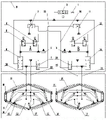
FIG. 1 is a gas path control schematic of the present invention;
FIG. 2 is a top plan view of the top box structure of the present invention;
FIG. 3 is a schematic view of the gas path when the first damper of the present invention is opened (in the open state of the first two-position three-way hand-pulled valve);
FIG. 4 is a schematic view of the air path when the first damper of the present invention is open (in the second two-position three-way hand-pulled valve open state);
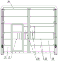
FIG. 5 is a front view of the present invention;
FIG. 6 is a schematic view of the open position of the damper of the present invention.
Reference numerals: 1. the air supply system comprises an air inlet main valve, 2, an air source processing element, 3 or 11, a two-position three-way pilot valve, 4 or 12, a second two-position three-way hand-pulling valve, 5 or 13, a first two-position three-way hand-pulling valve, 6 or 14, a large two-position five-way locking valve, 7 or 10, a small two-position five-way locking valve, 8 or 9, a one-way throttle valve, 15 or 16, a driving cylinder, 17, a pressure relief cylinder, 18, a front air door, 19, a counter air door, 20, a door post, 21, an air path control system, 22, a top box, 23, a rear cavity air supply pipe, 24, a front cavity air supply pipe, 25, a first pilot control air pipe, 26, a second pilot control air pipe, 27, a standard pedestrian door and 28, a lookout window.
Detailed Description
In order to make the technical purpose, technical solutions and advantages of the present invention more clear, the technical solutions of the present invention are further described below with reference to fig. 1 to 6 and specific embodiments.
Full servo positive and negative linkage air door's embodiment:
the full-servo positive and negative linkage air door comprises two air doors, each air door comprises two door posts, two positive air doors 18 and two negative air doors 19 are arranged between the two door posts, the positive air doors 18 and the negative air doors 19 are arc door leaves with the same structure, the full-servo positive and negative linkage air door also comprises two groups of pneumatic components for driving the arc door leaves and a set of air path control system 21 for controlling the pneumatic components, each group of pneumatic components respectively comprises four driving cylinders 15 and 16 respectively corresponding to the four arc door leaves, the positive air doors and the negative air doors in the same air door can be simultaneously controlled by the pneumatic components, the two air doors are opened, closed and interlocked through the air path control system 21,
the gas path control system 21 comprises a main gas inlet valve 1, a gas source processing element 2, a gas path A and a gas path B, wherein the gas source processing element 2 is respectively connected with the gas path A and the gas path B through a tee joint;
the structure of the gas circuit A is the same as that of the gas circuit B, the gas circuit A comprises a two-position three-way pilot valve 3, a first two-position three-way hand-pulled valve 5, a second two-position three-way hand-pulled valve 4, a large two-position five-way locking valve 6 and a small two-position five-way locking valve 7, the gas circuit B comprises a two-position three-way pilot valve 11, a first two-position three-way hand-pulled valve 13, a second two-position three-way hand-pulled valve 12, a large two-position five-way locking valve 14 and a small two-position five-way locking valve 10, the two-position three-way pilot valve, the first two-position three-way hand-pulled valve, the second two-position three-way hand-pulled valve, the large two-position five-way locking valve and the small two-position five-way locking valve are all pneumatic control valves, the pneumatic control valves are all of the existing structures, and the detailed structure is not repeated;
under the normal state, the respective working ports A of the two-position three-way pilot valve, the first two-position three-way hand-pulled valve and the second two-position three-way hand-pulled valve are communicated with the exhaust port R, and the respective working ports A of the large two-position five-way locking valve and the small two-position five-way locking valve are communicated with the air inlet P;
in a ventilation state, the working ports A of the two-position three-way pilot valve, the first two-position three-way hand-pulled valve and the second two-position three-way hand-pulled valve are communicated with the air inlet P, and the working ports B of the large two-position five-way locking valve and the small two-position five-way locking valve are communicated with the air inlet P;
working ports A of the two-position three- way pilot valves 3 and 11 are connected with the air source processing element 2, air inlets P of the two-position three- way pilot valves 3 and 11 are respectively connected with air inlets P of first two-position three-way hand-pulled valves 5 and 13 and second two-position three-way hand-pulled valves 4 and 12 through a tee, the working ports A of the first two-position three-way hand-pulled valves 5 and 13 and the working ports A of the second two-position three-way hand-pulled valves 4 and 12 are mutually connected, and exhaust ports R of the first two-position three-way hand-pulled valves 5 and 13 and exhaust ports R of the second two-position three-way hand-pulled valves 4 and 12 are respectively connected with control ports of big two-position five- way locking valves 6 and 14;
the air inlets P of the large two-position five- way locking valves 6 and 14 are connected with the air source processing element 2, the working ports B of the large two-position five- way locking valves 6 and 14 are respectively connected with the control ports of the rear cavity air supply pipe 23 and the small two-position five- way locking valves 7 and 10 through a tee joint, the working ports A of the large two-position five- way locking valves 6 and 14 are respectively connected with the air supply pipe 24 of the front cavity and the air inlets P of the small two-position five- way locking valves 7 and 10 through a tee joint, the working ports A of the small two-position five- way locking valves 7 and 10 in the air passage A are connected with the control ports of the two-position three- way pilot valves 3 and 11 in the air passage B through a first pilot control air pipe 25, and the working ports A of the small two-position five- way locking valves 7 and 10 in the air passage B are connected with the control ports of the two-position three- way pilot valves 3 and 11 in the air passage A through a second pilot control air pipe 26;
the air path A corresponds to a first air door, the air path B corresponds to a second air door, the rear cavity air supply pipes 23 in the two air paths are respectively communicated with the rear cavities of the driving cylinders 15 and 16 in the corresponding air doors through air pipes, and the front cavity air supply pipes 24 in the two air paths are respectively communicated with the front cavities of the driving cylinders 15 and 16 in the corresponding air doors through air pipes.
As one embodiment of the present invention, a top box 22 is installed above the door post of each air door, the pneumatic assembly is installed in the top box 22, the air path control system 21 is installed in the top box 22 and the door post, the cylinder seat of each driving cylinder is installed in the top box 22 through a hinged support, and the piston rod of each driving cylinder is hinged to the corresponding arc door leaf.
As one embodiment of the present invention, the air path a includes a one-way throttle valve 8, the air path B includes a one-way throttle valve 9, and the one- way throttle valves 8 and 9 are respectively connected to the exhaust port R of the first two-position three-way hand-pulled valve and the exhaust port R of the second two-position three-way hand-pulled valve. A one-way throttle valve may be used for exhaust.
The air source processing element 2 comprises an air filter, a pressure reducing valve and an oil atomizer as one embodiment of the invention.
As one embodiment of the present invention, the first two-position three-way hand-pulled valve and the second two-position three-way hand-pulled valve are respectively and correspondingly disposed on the front side and the rear side of the damper. Through setting up first two-position tee bend hand power valve and the second two-position tee bend hand power valve in the air door both sides, all can control the air door from the front and back side of air door and open the door in order to carry out the through-flow.
As one embodiment of the present invention, the pneumatic assembly further includes a pressure relief cylinder 17, a cylinder base of the pressure relief cylinder 17 is installed in the top box 22 through a hinged support, a piston rod of the pressure relief cylinder 17 extends out and then is in pressing contact with one of the positive air doors 18, a rear cavity of the pressure relief cylinder 17 is connected with a rear cavity air supply pipe 23 in the air path through an air pipe, and a front cavity of the pressure relief cylinder 17 is connected with a front cavity air supply pipe 24 in the air path through an air pipe. Because the positive air doors 18 are opened against the wind, when the door is opened, the pressure relief air cylinder 17 jacks one positive air door 18, the wind pressure difference at two sides of the positive air door can be reduced, and the door opening resistance is reduced.
As one embodiment of the invention, the keels of the top box 22 and the doorpost 20 are made of square steel pipes, the outer skins of the two surfaces of the arc-shaped door leaf are made of steel plates, and polyurea is sprayed on the surfaces of the steel plates. The polyurea material has flame retardant, strong corrosion resistance and high elasticity, and can effectively improve the double-sided safety of the door leaf.
As one embodiment of the invention, a standard pedestrian door 27 is arranged on one of the arc-shaped door leaves of each air door, and a lookout window 28 is arranged on each arc-shaped door leaf.
The air path control system 21 of the invention is connected with two air doors through two air paths to realize the functions of opening, closing and mutual locking, and the specific implementation mode is as follows:
as shown in fig. 1, fig. 3 and fig. 4, the air source enters the air source processing element 2 through the air inlet main valve 1, and is conveyed to the whole system after being processed by filtering and the like, in the air path a, when any one of the first two-position three-way hand-operated valve and the second two-position three-way hand-operated valve (respectively and correspondingly arranged on the front side and the rear side of the air door) in the air path a is opened, the control air path of the first air door is switched on, and two results are obtained:
(1) after the air source reaches the large two-position five-way locking valve 6 of the air path A, the large two-position five-way locking valve 6 is reversed, the air source is conveyed to the rear cavities of the driving cylinders 15 and 16 and the pressure relief cylinder 17 of the first air door through the working port B of the large two-position five-way locking valve 6, and the positive air door and the negative air door of the first air door are pushed to be opened simultaneously;
(2) meanwhile, the air source is changed over from the working port B of the big two-position five-way locking valve 6 to the control port of the small two-position five-way locking valve 7, the air inlet of the small two-position five-way locking valve 7 is cut off, so that no air source exists in the first pilot control air pipe 25, the two-position three-way pilot valve 11 in the second air door is in a closed state, no matter whether the first two-position three-way hand-pulled valve 13 or the second two-position three-way hand-pulled valve 12 in the air passage B is opened or not, the air source cannot reach the control port of the big two-position five-way locking valve 14, no pilot pressure exists at the control port of the big two-position five-way locking valve 14, the air source cannot provide power for the driving cylinders 15 and 16 of the second air door through the big two-position five-way locking valve 14 in the air passage B, and the second air door can still be in a closed state, namely, and locking is formed.
As shown in fig. 3 and 4, in the control gas path of the first damper, the gas source can directly and sequentially pass through the large two-position five-way latching valve 14, the small two-position five-way latching valve 10 and the second pilot control gas pipe 26 in the gas path B from the gas source processing element 2 to reach the control port of the two-position three-way pilot valve 3 in the gas path a, so that the working port a of the two-position three-way pilot valve 3 in the gas path a is communicated with the gas inlet P, and the gas source passes through the first two-position three-way hand pulling valve 5 or the second two-position three-way hand pulling valve 4 to reach the control port of the large two-position five-way latching valve 6 after coming out of the two-position three-way pilot valve 3, so that the large two-position five-way latching valve 6 is reversed.
Similarly, when any one of the first two-position three-way hand-operated valve and the second two-position three-way hand-operated valve (respectively correspondingly arranged on the front side and the rear side of the air door) in the air circuit B is opened, the control air circuit of the second air door is switched on, and two results are also obtained:
(1) after the air source reaches the large two-position five-way locking valve of the air passage B, the large two-position five-way locking valve is reversed, the air source is conveyed to the rear cavities of the driving cylinders 15 and 16 and the pressure relief cylinder 17 of the second air door through the working port B of the large two-position five-way locking valve, and the arc door leaves of the second air door are pushed to be opened;
(2) meanwhile, an air source is communicated to a control port of the small two-position five-way locking valve through a working port B of the large two-position five-way locking valve, the small two-position five-way locking valve is reversed, an air inlet of the small two-position five-way locking valve is cut off, and no air source exists in a second pilot control air pipe, so that a two-position three-way pilot valve in the first air door is in a closed state, no matter whether the first two-position three-way hand-pulled valve or the second two-position three-way hand-pulled valve in the air passage A is opened or not, the air source cannot reach the control port of the large two-position five-way locking valve, no pilot pressure exists at the control port of the large two-position five-way locking valve, the air source cannot provide power for a driving cylinder of the first air door through the large two-position five-way locking valve in the air passage A, and the first air door can still be in the closed state, and locking is formed.
In the control gas circuit of the second air door, a gas source can directly and sequentially reach a control port of a two-position three-way pilot valve of a gas circuit B from the gas source processing element 2 through a large two-position five-way locking valve, a small two-position five-way locking valve and a second pilot control gas pipe in the gas circuit A, so that a working port A of the two-position three-way pilot valve of the gas circuit B is communicated with a gas inlet P, and the gas source reaches the control port of the large two-position five-way locking valve through a first two-position three-way hand-pull valve or a second two-position three-way hand-pull valve after coming out of the two-position three-way pilot valve, so that the large two-position five-way locking valve is reversed.
The above embodiments are not intended to limit the shape, material, structure, etc. of the present invention in any way, and any simple modification, equivalent change and modification made to the above embodiments according to the technical spirit of the present invention are within the scope of the technical solution of the present invention.
Claims (10)
1. Full servo positive and negative linkage air door, including two air doors, every air door all includes two gateposts, installs two positive air doors and two anti-air doors between two gateposts, and positive air door and anti-air door are the same arc door leaf of structure, its characterized in that: the air door structure also comprises two groups of pneumatic components for driving the arc-shaped door leaves and a set of air path control system for controlling the pneumatic components, each group of pneumatic components respectively comprises four driving cylinders respectively corresponding to four arc-shaped door leaves, the two air doors are opened, closed and interlocked through the air path control system,
the gas path control system comprises a main gas inlet valve, a gas source processing element, a gas path A and a gas path B, wherein the gas source processing element is respectively connected with the gas path A and the gas path B through a tee joint;
the gas circuit A and the gas circuit B have the same structure, and the gas circuit A and the gas circuit B respectively comprise a two-position three-way pilot valve, a first two-position three-way hand-pulled valve, a second two-position three-way hand-pulled valve, a large two-position five-way locking valve and a small two-position five-way locking valve;
under the normal state, the respective working ports A of the two-position three-way pilot valve, the first two-position three-way hand-pulled valve and the second two-position three-way hand-pulled valve are communicated with the exhaust port R, and the respective working ports A of the large two-position five-way locking valve and the small two-position five-way locking valve are communicated with the air inlet P;
in a ventilation state, the working ports A of the two-position three-way pilot valve, the first two-position three-way hand-pulled valve and the second two-position three-way hand-pulled valve are communicated with the air inlet P, and the working ports B of the large two-position five-way locking valve and the small two-position five-way locking valve are communicated with the air inlet P;
the working port A of the two-position three-way pilot valve is connected with an air source processing element, the air inlet P of the two-position three-way pilot valve is respectively connected with the air inlet P of a first two-position three-way hand-pulled valve and a second two-position three-way hand-pulled valve through a tee, the working port A of the first two-position three-way hand-pulled valve is mutually connected with the working port A of the second two-position three-way hand-pulled valve, and the exhaust port R of the first two-position three-way hand-pulled valve and the exhaust port R of the second two-position three-way hand-pulled valve are respectively connected with the control port of the big two-position five-way locking valve;
the air inlet P of the large two-position five-way locking valve is connected with an air source processing element, the working port B of the large two-position five-way locking valve is respectively connected with the control ports of the rear cavity air supply pipe and the small two-position five-way locking valve through a tee joint, the working port A of the large two-position five-way locking valve is respectively connected with the air inlet P of the front cavity air supply pipe and the small two-position five-way locking valve through a tee joint, the working port A of the small two-position five-way locking valve in the air passage A is connected with the control port of the two-position three-way pilot valve of the air passage B through a first pilot control air pipe, and the working port A of the small two-position five-way locking valve in the air passage B is connected with the control port of the two-position three-way pilot valve of the air passage A through a second pilot control air pipe;
the air path A corresponds to the first air door, the air path B corresponds to the second air door, the back cavity air supply pipes in the two air paths are respectively communicated with the back cavities of the driving cylinders in the corresponding air doors through air pipes, and the front cavity air supply pipes in the two air paths are respectively communicated with the front cavities of the driving cylinders in the corresponding air doors through air pipes.
2. The full servo positive and negative linkage damper of claim 1, wherein: a top box is respectively installed above a door post of each air door, the pneumatic assembly is installed in the top box, the air path control system is installed in the top box and the door post, a cylinder seat of each driving cylinder is respectively installed in the top box through a hinged support, and a piston rod of each driving cylinder is respectively hinged with a corresponding arc door leaf.
3. The full servo positive and negative linkage damper of claim 1, wherein: the gas circuit A and the gas circuit B respectively comprise a one-way throttle valve, and the one-way throttle valve is respectively connected with the exhaust port R of the first two-position three-way hand-pulled valve and the exhaust port R of the second two-position three-way hand-pulled valve.
4. The full servo positive and negative linkage damper of claim 1, wherein: the air source processing element comprises an air filter, a pressure reducing valve and an oil atomizer.
5. The full servo positive and negative linkage damper of claim 1, wherein: the first two-position three-way hand-pulled valve and the second two-position three-way hand-pulled valve are respectively and correspondingly arranged on the front side and the rear side of the air door.
6. The full servo positive and negative linkage damper of claim 2, wherein: the pneumatic assembly further comprises a pressure relief air cylinder, a cylinder base of the pressure relief air cylinder is installed in the top box through a hinged support, a piston rod of the pressure relief air cylinder is in top pressure contact with one of the positive air doors after extending out, a rear cavity of the pressure relief air cylinder is connected with a rear cavity air supply pipe in the air path through an air pipe, and a front cavity of the pressure relief air cylinder is connected with a front cavity air supply pipe in the air path through an air pipe.
7. The full servo positive and negative linkage damper of claim 6, wherein: the keels of the top box and the doorpost are all made of square steel pipes, skins on the two surfaces of the arc-shaped door leaf are steel plates, and polyurea is sprayed on the surfaces of the steel plates.
8. The full servo positive and negative linkage damper of claim 7, wherein: and a standard pedestrian door is arranged on one of the arc-shaped door leaves of each air door, and an observation window is arranged on each arc-shaped door leaf.
9. The full-servo positive and negative linkage air door control method is characterized by comprising the following steps of: the method comprises the following steps:
a. the air source enters the air source processing element through the air inlet main valve, and is conveyed to the whole system after being processed by filtration and the like;
b. opening one of the air doors: opening a first two-position three-way hand-pulling valve or a second two-position three-way hand-pulling valve in the air passage A, connecting a control air passage of the first air door, reversing the large two-position five-way locking valve after an air source reaches the large two-position five-way locking valve of the air passage A, and conveying the air source to the rear cavities of each driving cylinder and each pressure relief cylinder of the first air door through a working port B of the large two-position five-way locking valve to push the positive air door and the negative air door of the first air door to be opened simultaneously;
c. and (3) locking the other air door: meanwhile, an air source is communicated to a control port of the small two-position five-way locking valve through a working port B of the large two-position five-way locking valve, the small two-position five-way locking valve is reversed, an air inlet of the small two-position five-way locking valve is cut off, no air source exists in the first pilot control air pipe, and therefore the two-position three-way pilot valve in the second air door is in a closed state.
10. The full servo positive and negative linkage damper control method of claim 9, wherein: the reversing process of the large two-position five-way locking valve in the step b is as follows: the air source directly and sequentially passes through the large two-position five-way locking valve, the small two-position five-way locking valve and the second pilot control air pipe in the air path B from the air source processing element to reach a control port of the two-position three-way pilot valve in the air path A, so that the working port A of the two-position three-way pilot valve in the air path A is communicated with the air inlet P, and the air source is discharged from the two-position three-way pilot valve and then passes through the first two-position three-way hand-pulled valve or the second two-position three-way hand-pulled valve to reach the control port of the large two-position five-way locking valve, so that the large two-position five-way locking valve is reversed.
Priority Applications (1)
| Application Number | Priority Date | Filing Date | Title |
|---|---|---|---|
| CN202110412847.0A CN113236334A (en) | 2021-04-16 | 2021-04-16 | Full-servo positive and negative linkage air door and control method |
Applications Claiming Priority (1)
| Application Number | Priority Date | Filing Date | Title |
|---|---|---|---|
| CN202110412847.0A CN113236334A (en) | 2021-04-16 | 2021-04-16 | Full-servo positive and negative linkage air door and control method |
Publications (1)
| Publication Number | Publication Date |
|---|---|
| CN113236334A true CN113236334A (en) | 2021-08-10 |
Family
ID=77128398
Family Applications (1)
| Application Number | Title | Priority Date | Filing Date |
|---|---|---|---|
| CN202110412847.0A Pending CN113236334A (en) | 2021-04-16 | 2021-04-16 | Full-servo positive and negative linkage air door and control method |
Country Status (1)
| Country | Link |
|---|---|
| CN (1) | CN113236334A (en) |
Citations (6)
| Publication number | Priority date | Publication date | Assignee | Title |
|---|---|---|---|---|
| CA2472545A1 (en) * | 2003-06-27 | 2004-12-27 | John M. Kennedy | Mine door system including an air pressure relief door |
| CN201574770U (en) * | 2009-12-31 | 2010-09-08 | 大同煤矿集团衡安装备有限公司 | Positive and negative air door device |
| CN203308491U (en) * | 2013-04-16 | 2013-11-27 | 大同煤矿集团衡安装备有限公司 | Positive-negative linkage pneumatic air door |
| CN103726864A (en) * | 2014-01-23 | 2014-04-16 | 大同煤矿集团衡安装备有限公司 | Forward and reverse linkage motorized air damper |
| CN111520177A (en) * | 2020-05-29 | 2020-08-11 | 大同煤矿集团衡安装备股份有限公司 | A kind of HA mine damper pneumatic control system |
| CN214660309U (en) * | 2021-04-16 | 2021-11-09 | 大同煤矿集团衡安装备股份有限公司 | Full-servo positive and negative linkage air door for mine |
-
2021
- 2021-04-16 CN CN202110412847.0A patent/CN113236334A/en active Pending
Patent Citations (6)
| Publication number | Priority date | Publication date | Assignee | Title |
|---|---|---|---|---|
| CA2472545A1 (en) * | 2003-06-27 | 2004-12-27 | John M. Kennedy | Mine door system including an air pressure relief door |
| CN201574770U (en) * | 2009-12-31 | 2010-09-08 | 大同煤矿集团衡安装备有限公司 | Positive and negative air door device |
| CN203308491U (en) * | 2013-04-16 | 2013-11-27 | 大同煤矿集团衡安装备有限公司 | Positive-negative linkage pneumatic air door |
| CN103726864A (en) * | 2014-01-23 | 2014-04-16 | 大同煤矿集团衡安装备有限公司 | Forward and reverse linkage motorized air damper |
| CN111520177A (en) * | 2020-05-29 | 2020-08-11 | 大同煤矿集团衡安装备股份有限公司 | A kind of HA mine damper pneumatic control system |
| CN214660309U (en) * | 2021-04-16 | 2021-11-09 | 大同煤矿集团衡安装备股份有限公司 | Full-servo positive and negative linkage air door for mine |
Similar Documents
| Publication | Publication Date | Title |
|---|---|---|
| CN101408107B (en) | Energy-saving type shield propulsion hydraulic system by using zone control | |
| CN201288566Y (en) | Energy-saving shield advance hydraulic system employing zone control | |
| DE102012105976A1 (en) | Steering system for follower axis of vehicle, has working cylinder delivering hydraulic fluid through central bore, so that piston is movably floated in center position in which follower axis of impellers is blocked in straight position | |
| CN214660309U (en) | Full-servo positive and negative linkage air door for mine | |
| CN111520177B (en) | A pneumatic control system for HA mine air door | |
| CN103465957B (en) | The Multi-mode steering hydraulic control of a kind of manual switching and wheeled crane | |
| CN113236334A (en) | Full-servo positive and negative linkage air door and control method | |
| CN201262094Y (en) | Pneumatic damper interlocking device for coal mine underground air duct | |
| CN214660307U (en) | Full-servo safety interlocking air door for mine | |
| CN202952984U (en) | Side door of cab of railway vehicle | |
| CN113513355B (en) | Full-servo safety interlocking air door and control method | |
| CN203308491U (en) | Positive-negative linkage pneumatic air door | |
| CN205315005U (en) | Emergent hydraulic means of slurry shield machine circulation system | |
| CN207526788U (en) | A kind of hydraulic system of combined tractor | |
| CN206299631U (en) | A kind of garbage-compressing control integral multitandem valve | |
| CN212508396U (en) | HA mine air door pneumatic control system | |
| CN221257282U (en) | Oil circuit switching valve assembly | |
| CN220451829U (en) | Electrohydraulic integrated valve group structure for controlling duplex blowout prevention box | |
| CN111255329B (en) | Device and control method for quickly opening a passenger door of a passenger car | |
| CN206636593U (en) | Air door interlocked system and locking air door | |
| CN213945545U (en) | High-efficient safe driving chain assembly tool | |
| CN222835804U (en) | Underground air door pneumatic control system | |
| CN203485988U (en) | Manual switching type multi-mode steering hydraulic control system and wheeled crane | |
| CN208439259U (en) | A kind of underground ventilating air door pneumatic automatic stop block | |
| CN202063684U (en) | Lateral shifting and distance adjusting device for pallet fork of fork truck |
Legal Events
| Date | Code | Title | Description |
|---|---|---|---|
| PB01 | Publication | ||
| PB01 | Publication | ||
| SE01 | Entry into force of request for substantive examination | ||
| SE01 | Entry into force of request for substantive examination | ||
| RJ01 | Rejection of invention patent application after publication |
Application publication date: 20210810 |
|
| RJ01 | Rejection of invention patent application after publication |