CN113236607A - Design method of large-scale engineering pump volute and volute thereof - Google Patents

Design method of large-scale engineering pump volute and volute thereof Download PDF

Info

Publication number
CN113236607A
CN113236607A CN202110658301.3A CN202110658301A CN113236607A CN 113236607 A CN113236607 A CN 113236607A CN 202110658301 A CN202110658301 A CN 202110658301A CN 113236607 A CN113236607 A CN 113236607A
Authority
CN
China
Prior art keywords
volute
section
pump
guide vane
outlet
Prior art date
Legal status (The legal status is an assumption and is not a legal conclusion. Google has not performed a legal analysis and makes no representation as to the accuracy of the status listed.)
Granted
Application number
CN202110658301.3A
Other languages
Chinese (zh)
Other versions
CN113236607B (en
Inventor
李晓俊
宁望辉
马建峰
林言丕
朱祖超
Current Assignee (The listed assignees may be inaccurate. Google has not performed a legal analysis and makes no representation or warranty as to the accuracy of the list.)
Zhejiang University of Technology ZJUT
Original Assignee
Zhejiang University of Technology ZJUT
Priority date (The priority date is an assumption and is not a legal conclusion. Google has not performed a legal analysis and makes no representation as to the accuracy of the date listed.)
Filing date
Publication date
Application filed by Zhejiang University of Technology ZJUT filed Critical Zhejiang University of Technology ZJUT
Priority to CN202110658301.3A priority Critical patent/CN113236607B/en
Publication of CN113236607A publication Critical patent/CN113236607A/en
Priority to JP2022046608A priority patent/JP7689689B2/en
Application granted granted Critical
Publication of CN113236607B publication Critical patent/CN113236607B/en
Active legal-status Critical Current
Anticipated expiration legal-status Critical

Links

Images

Classifications

    • FMECHANICAL ENGINEERING; LIGHTING; HEATING; WEAPONS; BLASTING
    • F04POSITIVE - DISPLACEMENT MACHINES FOR LIQUIDS; PUMPS FOR LIQUIDS OR ELASTIC FLUIDS
    • F04DNON-POSITIVE-DISPLACEMENT PUMPS
    • F04D29/00Details, component parts, or accessories
    • F04D29/40Casings; Connections of working fluid
    • F04D29/42Casings; Connections of working fluid for radial or helico-centrifugal pumps
    • F04D29/426Casings; Connections of working fluid for radial or helico-centrifugal pumps especially adapted for liquid pumps
    • FMECHANICAL ENGINEERING; LIGHTING; HEATING; WEAPONS; BLASTING
    • F04POSITIVE - DISPLACEMENT MACHINES FOR LIQUIDS; PUMPS FOR LIQUIDS OR ELASTIC FLUIDS
    • F04DNON-POSITIVE-DISPLACEMENT PUMPS
    • F04D29/00Details, component parts, or accessories
    • F04D29/40Casings; Connections of working fluid
    • F04D29/42Casings; Connections of working fluid for radial or helico-centrifugal pumps
    • F04D29/44Fluid-guiding means, e.g. diffusers
    • F04D29/445Fluid-guiding means, e.g. diffusers especially adapted for liquid pumps
    • F04D29/448Fluid-guiding means, e.g. diffusers especially adapted for liquid pumps bladed diffusers
    • FMECHANICAL ENGINEERING; LIGHTING; HEATING; WEAPONS; BLASTING
    • F04POSITIVE - DISPLACEMENT MACHINES FOR LIQUIDS; PUMPS FOR LIQUIDS OR ELASTIC FLUIDS
    • F04DNON-POSITIVE-DISPLACEMENT PUMPS
    • F04D29/00Details, component parts, or accessories
    • F04D29/40Casings; Connections of working fluid
    • F04D29/42Casings; Connections of working fluid for radial or helico-centrifugal pumps
    • F04D29/44Fluid-guiding means, e.g. diffusers
    • F04D29/46Fluid-guiding means, e.g. diffusers adjustable
    • F04D29/466Fluid-guiding means, e.g. diffusers adjustable especially adapted for liquid fluid pumps
    • GPHYSICS
    • G06COMPUTING OR CALCULATING; COUNTING
    • G06FELECTRIC DIGITAL DATA PROCESSING
    • G06F30/00Computer-aided design [CAD]
    • G06F30/10Geometric CAD
    • G06F30/17Mechanical parametric or variational design
    • FMECHANICAL ENGINEERING; LIGHTING; HEATING; WEAPONS; BLASTING
    • F05INDEXING SCHEMES RELATING TO ENGINES OR PUMPS IN VARIOUS SUBCLASSES OF CLASSES F01-F04
    • F05DINDEXING SCHEME FOR ASPECTS RELATING TO NON-POSITIVE-DISPLACEMENT MACHINES OR ENGINES, GAS-TURBINES OR JET-PROPULSION PLANTS
    • F05D2250/00Geometry
    • F05D2250/50Inlet or outlet
    • F05D2250/52Outlet
    • FMECHANICAL ENGINEERING; LIGHTING; HEATING; WEAPONS; BLASTING
    • F05INDEXING SCHEMES RELATING TO ENGINES OR PUMPS IN VARIOUS SUBCLASSES OF CLASSES F01-F04
    • F05DINDEXING SCHEME FOR ASPECTS RELATING TO NON-POSITIVE-DISPLACEMENT MACHINES OR ENGINES, GAS-TURBINES OR JET-PROPULSION PLANTS
    • F05D2250/00Geometry
    • F05D2250/70Shape

Landscapes

  • Engineering & Computer Science (AREA)
  • General Engineering & Computer Science (AREA)
  • Mechanical Engineering (AREA)
  • Physics & Mathematics (AREA)
  • Geometry (AREA)
  • General Physics & Mathematics (AREA)
  • Theoretical Computer Science (AREA)
  • Computational Mathematics (AREA)
  • Mathematical Analysis (AREA)
  • Mathematical Optimization (AREA)
  • Pure & Applied Mathematics (AREA)
  • Computer Hardware Design (AREA)
  • Evolutionary Computation (AREA)
  • Structures Of Non-Positive Displacement Pumps (AREA)

Abstract

本发明公开了一种大型工程泵蜗壳的设计方法及其蜗壳,其包括蜗壳出口、扩散段(2)、喉部(3)、活动导叶(5)、固定导叶(6)、出口导叶(7)、隔舌(8),活动导叶的外周设置有多个固定导叶,出口导叶大体上与压水室进口基圆D3相切,出口导叶的进口端具有截面I,隔舌处具有截面II,在流动方向上从截面II到截面I,蜗壳为环形蜗壳,蜗壳的流道横截面流通面积基本相同。采用带固定导叶及活动导叶的环形蜗壳结构,根据给定工况,基于蜗壳速度系数法确定蜗壳的几何参数,包括压水室进口基圆直径D3,泵压水室进口宽度B3,蜗室的外轮廓线半径R,活动导叶数Z1,固定导叶数z2’,扩散角θ。其能够降低泵运行过程中的压力脉动及径向力,加强泵各个工况下的运行安全性和稳定性。

Figure 202110658301

The invention discloses a design method for a volute casing of a large-scale engineering pump and the volute casing thereof, which comprises an outlet of the volute casing, a diffusion section (2), a throat (3), a movable guide vane (5), and a fixed guide vane (6). , outlet guide vane (7), separating tongue (8), the outer periphery of the movable guide vane is provided with a plurality of fixed guide vanes, the outlet guide vane is substantially tangent to the inlet base circle D3 of the pressurized water chamber, and the inlet end of the outlet guide vane has Section I, the separation tongue has section II, from section II to section I in the flow direction, the volute is an annular volute, and the cross-sectional flow area of the flow channel of the volute is basically the same. The annular volute structure with fixed guide vanes and movable guide vanes is adopted. According to the given working conditions, the geometric parameters of the volute are determined based on the volute velocity coefficient method, including the base circle diameter D 3 of the inlet of the pressurized water chamber, and the inlet of the pump pressurized water chamber. The width B 3 , the radius R of the outer contour of the scroll chamber, the number of movable guide vanes Z 1 , the number of fixed guide vanes z 2' , and the diffusion angle θ. It can reduce the pressure pulsation and radial force during the operation of the pump, and enhance the operation safety and stability of the pump under various working conditions.

Figure 202110658301

Description

Design method of large-scale engineering pump volute and volute thereof
Technical Field
The invention relates to the technical field of hydraulic engineering pump volutes and centrifugal pump volutes, in particular to a design method of a large-scale engineering pump volute and the volute.
Background
In recent years, the water conservancy and hydropower engineering in China is developed greatly, and a solid foundation is laid for the implementation of sustainable development strategies in China while the requirement of the supply and demand of electric power energy in China is met. The volute is an important flow passage component of the centrifugal pump and has great influence on the efficiency index of the pump. When fluid enters the volute from the impeller, strong interaction can occur due to small clearance between the impeller and the volute partition tongue/tongue part, and high-amplitude low-frequency pressure pulsation is caused in the conventional spiral volute partition tongue area; meanwhile, as the geometric structure of the spiral volute is in an asymmetric form, when the lift and the flow are high, large pressure pulsation and radial force can be generated, large vibration or noise is generated, and the operation stability of the large hydraulic engineering pump is influenced. To solve the problem, the chinese patent application publication No. CN201218236Y discloses a high-speed water pump volute, which comprises a flat volute circular bottom with involute or archimedean volute and a continuous side wall forming a continuous volute, and a volute with a pump inlet and a pump outlet, wherein the center of the volute is a water inlet, the continuous side wall is a water baffle, the lift height and the water flow are enhanced, and the volute has the characteristics of light weight, corrosion resistance, easy manufacture and low cost; chinese patent application publication No. CN111894903A discloses a serial single-stage centrifugal pump volute and a design method thereof, when different pump flows and impeller outer diameters are designed, the axial wall thickness of the pump body close to the pump cover side can be the same, and the pump cover can be designed into a general shape. The pumping chamber adopts an axially asymmetric section, the center line is used as a reference, the section close to the pump cover side is rectangular, and the other side is in a right trapezoid shape, so that the deflection of the rotating shaft is effectively reduced, the sealing reliability is improved, and the vibration of the pump is reduced. However, although the production efficiency is improved, the mechanical strength is improved, and the pressure pulsation is reduced to a certain extent, the pump head with the trapezoidal or rectangular section is adopted, and the efficiency is low. Therefore, it is necessary to design a volute structure of a large hydraulic engineering pump, which can be widely applied and can stably and efficiently operate with small pressure pulsation and radial force.
The structure of the traditional volute comprises a volute body, wherein a water flow channel is arranged in the volute body, and the water flow channel generally consists of a water pumping chamber and a diffusion section. The starting end of the water pressing chamber is a separation tongue, the joint of the water pressing chamber and the diffusion section is a throat part, and the outlet of the diffusion section is a pump body outlet; the traditional pumping chamber is formed by connecting a group of sections, wherein the sections of the sections are gradually increased from the positions of the partition tongues to the throat part of the inlet of the diffusion section of the pump along the rotation direction of the impeller, and the cross section of the pumping chamber is an eccentric ellipse, a trapezoid or a semi-arc section so as to improve the pumping head and the efficiency of the pump.
Disclosure of Invention
The invention aims to overcome the defects in the prior art and provides a design method of a volute of a large-scale engineering pump and the volute thereof, which can reduce pressure pulsation and radial force in the operation process of the pump and enhance the operation safety and stability of the pump under various working conditions.
In order to achieve the purpose, the invention adopts the technical scheme that:
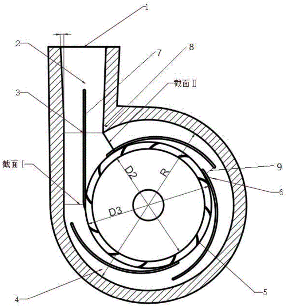
the utility model provides a spiral case of large-scale engineering pump, it includes spiral case export (1), diffuser section (2), throat (3), fixed multithread way (4), activity stator (5), stator (6), export stator (7), separate tongue/tongue portion (8), runner clearance (9), the exit end of pressurized-water chamber is equipped with the diffuser section, the exit end of diffuser section has the spiral case export, connecting portion between pressurized-water chamber and the diffuser section are the throat, the impeller periphery is equipped with the diffuser, the diffuser includes a plurality of movable stator that distribute along circumference, constitute between diffuser section and the spiral case wall and separate the tongue, its characterized in that: the periphery of the movable guide vane (5) is provided with a plurality of fixed guide vanes (6), the fixed guide vanes divide a volute flow passage into fixed multi-flow passages, the center line/axis of the outlet guide vane is collinear/parallel with the center line/axis of the diffusion section, the outlet guide vane is generally tangent to a pumping chamber inlet base circle D3, a flow passage gap (9) is formed between the outlet end of the fixed guide vane and the inlet end of the fixed guide vane or the pumping chamber inlet base circle D3 on the radial inner side adjacent to the outlet guide vane, the inlet end of the outlet guide vane is provided with a section I, the partition tongue is provided with a section II, the volute is an annular volute from the section II to the section I in the flow direction, and the flow passage cross section flow areas of the volute are basically the same.
Further, the volute adopts a generally eccentric oval-section annular volute, and the size of the oval eccentric long part is 2-4 times that of the short part in the oval long axis direction.
Further, the fixed guide vanes (6) are arc-shaped guide vanes, have different central angles, and the central angles are gradually increased from the section II to the section I in the flow direction; from section II to section I in the direction of flow, the downstream central angle is 1.05-1.25 times the upstream central angle.
Further, the flow channel gap (9) gradually increases from the section II to the section I in the flow direction; and the flow channel gap at the downstream is 1.05-1.2 times of the flow channel gap at the upstream from the section II to the section I in the flow direction.
Further, the fixed guide vane (6) is provided with a downstream end/tail edge end (61), the downstream end is in a tapered conical shape or an arc shape, the downstream end is provided with a first groove (62) and a second groove (63), the first grooves are arranged on the radial inner side surface of the downstream end, and the second grooves are arranged on the radial outer side surface of the downstream end; the first groove and the second groove are of semicircular structures.
Further, the number of the first grooves (62) is larger than that of the second grooves (63), and the number of the first grooves is 1.5-3.0 times that of the second grooves.
Furthermore, the diffusion section is a pump body outlet, the diffusion section is from the throat to a volute outlet, the area of a water flow channel is gradually increased, and the section of the diffusion section comprises a shape consisting of a rectangle and/or an arc; the shape of the cross section of the water pumping chamber at the throat part is the same as and coincided with the shape of the end face of the diffusion section, and the structure ensures the smooth transition of the water pumping chamber and the diffusion section.
A design method for a volute of a large-scale engineering pump is characterized in that a volute with fixed guide vanes and movable guide vanes is adoptedThe annular volute structure determines the geometric parameters of the volute based on a volute speed coefficient method according to given working conditions, wherein the geometric parameters comprise the inlet base circle diameter D of the pumping chamber3Width of inlet of pumping water chamber B3Radius of outer contour line of volute, number of movable vanes Z1Fixed number of guide blades Z2The divergence angle θ;
the method comprises the following design steps:
(1) Design of the base diameter D of the inlet of the pumping chamber3
D3=D2+2b2
In the formula:
b2-movable guide vane radius, mm;
D2-pump impeller outer diameter, mm;
D3-pump water chamber inlet base circle diameter, mm;
(2) design pump pressure water chamber inlet width B3
B3=B2+0.05D3
In the formula:
B2-pump impeller outlet axial width, mm;
D3-pump water chamber inlet base circle diameter, mm;
B3-width of inlet of pumping water chamber, mm;
(3) designing the outer contour line radius R of the volute:
Figure BDA0003113146920000041
in the formula:
AI-area value of volute I section, mm;
r-the radius of the outer contour line of the volute chamber, mm;
(4) design of number of movable vanes Z1
Z1=8~14
In the formula:
Z1-number of active guide vanes;
(5) design of fixed number of guide vanes Z2
Z2=3~5
In the formula:
Z2-a fixed number of guide vanes;
(6) designing a diffusion angle of a diffusion section:
Figure BDA0003113146920000042
in the formula:
AI-area value of volute I section, mm;
DS-volute exit diameter, mm;
l-the length of the volute diffusion section is mm;
theta-spread angle, °;
the theta is adopted to be 6-12 degrees.
The invention has the beneficial technical effects that:
(1) by adopting the structure of the annular volute, compared with a typical spiral volute, the annular volute has symmetrical overflowing flow channels, and a larger gap is formed between the partition tongue and the impeller outlet, so that the traditional volute is replaced by the annular volute, the pump pressure pulsation and the radial force can be reduced, and the operation stability is improved. The clearance between the periphery of the impeller and the volute partition tongue is increased, the volute partition tongue structure has the advantages that the collision of water flow on the volute partition tongue is reduced, and the increase of the clearance between the partition tongue and the impeller can reduce pressure pulsation and integral radial force.
(2) By further designing the stay vanes with different central angles and increasing the central angle from section II to section I in the flow direction. The flow channel gap gradually increases from section II to section I in the flow direction. The pressure pulsation and the radial force in the operation process of the pump can be further reduced, the corner vortex at the outlet of the fixed guide vane is reduced, the pressure fluctuation and the pressure loss of the annular volute are reduced, and the operation safety and the stability of the pump under various working conditions are enhanced. According to the invention, through the design of the first groove and the second groove, the corner vortex at the outlet of the fixed guide vane can be further reduced, and the pressure fluctuation and pressure loss of the annular volute are reduced, so that the operation safety and stability of the pump under various working conditions are enhanced.
(3) The double rows of guide vanes (movable guide vanes and fixed guide vanes) are arranged in the volute to collect high-speed liquid thrown out by the impeller, and the high-speed liquid is uniformly guided to an inlet or an extrusion chamber of the next-stage impeller, and partial kinetic energy of the liquid can be converted into pressure energy in the guide vanes, so that the efficiency of the pump is improved. Compared with the fixed guide vane-free or single-row fixed guide vane, the hydraulic performance of the double-row guide vane is greatly improved. And the cross section of the volute is combined to adopt an eccentric elliptical cross section, the influence of the cross section shape on the hydraulic performance of the centrifugal pump is analyzed, and the elliptical cross section shape under the annular volute can provide a pump head higher than a trapezoidal, semicircular or rectangular shape.
Drawings
FIG. 1 is a schematic diagram of the construction of an annular volute for a pump of the present invention;
FIG. 2 is a partial comparison of an annular volute and a spiral volute, (a) the annular volute, and (b) the spiral volute;
FIG. 3 is a comparison of spiral and ring volute cross-sections (A is spiral volute and B is ring volute);
FIG. 4 is a graph of toroidal and spiral volutes versus pump performance;
FIG. 5 is a partial enlarged schematic view of another embodiment of a stay vane of the present invention.
In the figure: the volute comprises a volute outlet 1, a diffusion section 2, a throat 3, a fixed multi-channel 4, a movable guide vane 5, a fixed guide vane 6, an outlet guide vane 7, a partition tongue/tongue portion 8, a flow channel gap 9, a D2 impeller outer diameter, a D3 pumping chamber inlet base circle diameter, an R volute outer contour line radius, a downstream end/trailing edge end 61, a first groove 62 and a second groove 63.
Detailed Description
In order to make the objects, technical solutions and advantages of the embodiments of the present invention clearer, the technical solutions in the embodiments of the present invention will be clearly and completely described below with reference to the drawings in the embodiments of the present invention, and it is obvious that the described embodiments are some, but not all, embodiments of the present invention. All other embodiments, which can be derived by a person skilled in the art from the embodiments given herein without making any creative effort, shall fall within the protection scope of the present invention.
The present invention will be described in further detail with reference to the accompanying drawings.
As shown in fig. 1-2, a design method of a large-scale engineering pump volute and the volute thereof, which comprises a volute outlet 1, a diffuser 2, a throat 3, a fixed multi-flow channel 4, a movable guide vane 5, a fixed guide vane 6, an outlet guide vane 7, a tongue/tongue portion 8 and a flow channel gap 9, wherein the diffuser 2 is arranged at the outlet end of a pressurized water chamber, the volute outlet 1 is arranged at the outlet end of the diffuser 2, the throat 3 is arranged at the connecting part between the pressurized water chamber and the diffuser 2, a diffuser is arranged at the periphery of an impeller and comprises a plurality of movable guide vanes 5 distributed along the circumferential direction, and the tongue 8 is formed between the diffuser 2 and the volute wall, and is characterized in that: the periphery of the movable guide vane 5 is provided with a plurality of fixed guide vanes 6, the fixed guide vanes 6 divide a volute flow passage into fixed multi-flow passages 4, the center line/axis of the outlet guide vane 7 is collinear/parallel with the center line/axis of the diffusion section 2, the outlet guide vane 7 is generally tangent to a pumping chamber inlet base circle D3, a flow passage gap 9 is formed between the outlet end of the fixed guide vane 6 and the inlet end of the fixed guide vane 6 at the radial inner side adjacent to the outlet end of the fixed guide vane 6 or the pumping chamber inlet base circle D3, the inlet end of the outlet guide vane 7 is provided with a section I, a section II is arranged at the partition tongue 8, the section II is from the section II to the section I in the flow direction, the volute is an annular volute, and the flow passage cross section flow areas of the volutes are the same.
Further, as shown in fig. 3, the volute employs a substantially eccentric oval-section annular volute B, and the size of the oval eccentric long portion is 2 to 4 times, preferably 2.5 times, the size of the short portion in the oval long axis direction (X-axis direction).
Further, the stay vanes 6 are arc-shaped vanes, and the stay vanes 6 have the same or different central angles. Preferably, the stay vanes 6 have different central angles and the central angles increase progressively from section II to section I in the direction of flow. Specifically, from section II to section I in the flow direction, the downstream central angle is 1.05-1.25 times the upstream central angle.
Further, the flow passage gap 9 gradually increases from the section II to the section I in the flow direction. Specifically, the downstream flow channel gap 9 is 1.05-1.2 times the upstream flow channel gap 9 from section II to section I in the flow direction.
As shown in fig. 1, the volute has substantially the same cross-sectional flow area in the direction of flow from cross-section II to cross-section I, and then the clearance between the impeller outer circumference and the volute tongue 8 is increased, which has the advantage of reducing the impact of solid particles on the volute tongue, and the increased clearance between the tongue and the impeller reduces pressure pulsations and overall radial forces.
The diffusion section 2 is a pump body outlet, the diffusion section is from the throat 3 to the volute outlet 1, the area of a water flow channel is gradually increased, and the cross section of the diffusion section comprises a shape formed by a rectangle and/or an arc. The shape of the cross section of the water pumping chamber at the throat part 3 is the same as and coincided with the shape of the end surface of the diffuser section 2, and the structure ensures the smooth transition of the water pumping chamber and the diffuser section.
As shown in fig. 2, the annular volute has a larger, more uniform cross-sectional flow area than a conventional spiral volute. Too small a cross-sectional area of the volute can cause a hump in the pump head curve, thereby causing surge in the piping system. Under a rated working condition, the hydraulic performance is slightly reduced along with the increase of the overflowing area of the volute; when the operation of the pump deviates from the rated working condition, the hydraulic performance is improved under the condition that the flow area of the volute is larger; furthermore, as the volute flow area increases, the high efficiency zone will widen.
Instead of a conventional trapezoidal or semi-circular volute cross-section, the volute has a generally eccentric elliptical cross-section, which is advantageous for reducing pressure pulsations in the volute.
By using an annular volute, as shown in fig. 4(a), the radial force can be reduced in the low flow range; also, these volutes produce more lift and efficiency when the pump is operating below the optimum efficiency point. The interaction between the impeller blades and the volute diaphragm is reduced in these volutes due to the larger tip clearance, and therefore the pressure distribution around the impeller becomes more uniform. At design time, the pressure distribution around the impeller is not uniform due to the constant cross-sectional area volute, which results in the point of minimum radial force being at low flow, not the design flow.
The radial force distribution is shown as a quadrilateral from fig. 4(b), consistent with the impeller blade angle; in addition, along with the increase of the flow rate, the quadrangle rotates clockwise, the increase of the flow area of the volute can reduce the magnitude of radial force acting on the shaft, and particularly under the conditions of nominal flow rate and large flow rate, the vibration of the pump can be reduced, so that the operation stability of the pump is improved.
As shown in fig. 4(c), as can be seen from the broken line distribution of the fluctuation intensity coefficient in the center-of-annulus volute, the coefficient increases as a whole with the increase in flow rate; in addition, the polyline all shows four peaks, which correspond to the number of impeller blades, the equivalent deflection angle of the four peaks is 90 °, the maximum pressure pulsation occurs at about 30 ° behind the volute tongue, which means that the interaction between the impeller trailing edge and the volute tongue is the main cause of the pressure pulsation in the volute. Additionally, the increase in volute flow area will mitigate pressure pulsations in the volute regardless of the operating conditions of the pump.
Preferably, the stator vanes 6 are further designed to have different central angles, and the central angles gradually increase from section II to section I in the flow direction. The flow channel gap 9 gradually increases from section II to section I in the flow direction. The pressure pulsation and the radial force in the operation process of the pump can be further reduced, the corner vortex at the outlet of the fixed guide vane is reduced, the pressure fluctuation and the pressure loss of the annular volute are reduced, and the operation safety and the stability of the pump under various working conditions are enhanced.
As shown in fig. 5, in an embodiment, the stationary vane 6 has a downstream/trailing end 61, the downstream/trailing end 61 is tapered or curved, the downstream end 61 has a first groove 62 and a second groove 63, the first grooves 62 are disposed on a radially inner side of the downstream end 61, and the second grooves 63 are disposed on a radially outer side of the downstream end 61; the first groove 62 and the second groove 63 are semi-circular structures. Through the design of the first groove 62 and the second groove 63, the corner vortex at the outlet of the fixed guide vane can be further reduced, and the pressure fluctuation and the pressure loss of the annular volute are reduced, so that the operation safety and the stability of the pump under various working conditions are enhanced.
Further, the number of the first grooves 62 is greater than the number of the second grooves 63, and preferably, the number of the first grooves 62 is 1.5 to 3.0 times the number of the second grooves 63.
A design method of a volute of a large-scale engineering pump adopts an annular volute structure with fixed guide vanes and movable guide vanes, and determines geometric parameters of the volute based on a volute speed coefficient method according to given working conditions, wherein the geometric parameters comprise a basic circle diameter D of an inlet of a pumping chamber3Width of inlet of pumping water chamber B3Radius of outer contour line of volute, number of movable vanes Z1Fixed number of guide vanes z2The divergence angle θ;
the method comprises the following design steps:
(1) design of the base diameter D of the inlet of the pumping chamber3
D3=D2+2b2
In the formula:
b2-movable guide vane radius, mm;
D2-pump impeller outer diameter, mm;
D3-pump water chamber inlet base circle diameter, mm;
(2) design pump pressure water chamber inlet width B3
B3=B2+0.05D3
In the formula:
B2-pump impeller outlet axial width, mm;
D3-pump water chamber inlet base circle diameter, mm;
B3-width of inlet of pumping water chamber, mm;
(3) designing the outer contour line radius R of the volute:
Figure BDA0003113146920000091
in the formula:
AI-area value of volute I section, mm;
r-the radius of the outer contour line of the volute chamber, mm;
(4) designing movable guide vanesNumber Z1
Z1=8~14
In the formula:
Z1-number of active guide vanes;
(5) design of fixed number of guide vanes Z2
Z2=3~5
In the formula:
Z2-a fixed number of guide vanes;
(6) designing a diffusion angle of a diffusion section:
Figure BDA0003113146920000101
in the formula:
AI-area value of volute I section, mm;
DS-volute exit diameter, mm;
l-the length of the volute diffusion section is mm;
theta-spread angle, °;
the theta is adopted to be 6-12 degrees.
In order to reduce the volume of the pump, the diameter of a discharge pipeline and the loss of the pipeline, thereby reducing the lift of the pump, reducing the power of the pump, saving energy, reducing the operation cost, and taking the discharge caliber to be smaller than the suction caliber. The diameter of the outlet of the pump is preliminarily determined and then should be rounded according to the diameter series of the standard pipeline, and the height L of the diffusion pipe/diffusion section should be measured to a small value as much as possible under the condition of ensuring the diffusion angle, processing and bolt connection so as to reduce the size of the pump.
The invention has the beneficial technical effects that:
(1) by adopting the structure of the annular volute, compared with a typical spiral volute, the annular volute has symmetrical overflowing flow channels, and a larger gap is formed between the partition tongue and the impeller outlet, so that the traditional volute is replaced by the annular volute, the pump pressure pulsation and the radial force can be reduced, and the operation stability is improved. The clearance between the periphery of the impeller and the volute partition tongue is increased, the volute partition tongue structure has the advantages that the collision of water flow on the volute partition tongue is reduced, and the increase of the clearance between the partition tongue and the impeller can reduce pressure pulsation and integral radial force.
(2) By further designing the stay vanes with different central angles and increasing the central angle from section II to section I in the flow direction. The flow channel gap gradually increases from section II to section I in the flow direction. The pressure pulsation and the radial force in the operation process of the pump can be further reduced, the corner vortex at the outlet of the fixed guide vane is reduced, the pressure fluctuation and the pressure loss of the annular volute are reduced, and the operation safety and the stability of the pump under various working conditions are enhanced. According to the invention, through the design of the first groove and the second groove, the corner vortex at the outlet of the fixed guide vane can be further reduced, and the pressure fluctuation and pressure loss of the annular volute are reduced, so that the operation safety and stability of the pump under various working conditions are enhanced.
(3) The double rows of guide vanes (movable guide vanes and fixed guide vanes) are arranged in the volute to collect high-speed liquid thrown out by the impeller, and the high-speed liquid is uniformly guided to an inlet or an extrusion chamber of the next-stage impeller, and partial kinetic energy of the liquid can be converted into pressure energy in the guide vanes, so that the efficiency of the pump is improved. Compared with the fixed guide vane-free or single-row fixed guide vane, the hydraulic performance of the double-row guide vane is greatly improved. And the cross section of the volute is combined to adopt an eccentric elliptical cross section, the influence of the cross section shape on the hydraulic performance of the centrifugal pump is analyzed, and the elliptical cross section shape under the annular volute can provide a pump head higher than a trapezoidal, semicircular or rectangular shape.
The above-described embodiments are illustrative of the present invention and not restrictive, it being understood that various changes, modifications, substitutions and alterations can be made herein without departing from the principles and spirit of the invention, the scope of which is defined by the appended claims and their equivalents.

Claims (8)

1.一种大型工程泵的蜗壳,其包括蜗壳出口(1)、扩散段(2)、喉部(3)、固定式多流道(4)、活动导叶(5)、固定导叶(6)、出口导叶(7)、隔舌/舌部(8)、流道间隙(9),压水室的出口端设有扩散段,扩散段的出口端具有蜗壳出口,压水室与扩散段之间的连接部为喉部,叶轮外周设有扩压器,扩压器包括多个沿周向分布的活动导叶,扩散段与蜗壳壁之间构成隔舌,其特征在于:活动导叶(5)的外周设置有多个固定导叶(6),固定导叶将蜗壳流道分隔为固定式多流道,出口导叶的中线/轴线与扩散段的中线/轴线共线/平行,出口导叶大体上与压水室进口基圆D3相切,固定导叶的出口端与与其相邻的径向内侧的固定导叶的进口端或压水室进口基圆D3之间具有流道间隙(9),出口导叶的进口端具有截面I,隔舌处具有截面II,在流动方向上从截面II到截面I,蜗壳为环形蜗壳,蜗壳的流道横截面流通面积基本相同。1. A volute of a large engineering pump, comprising a volute outlet (1), a diffuser section (2), a throat (3), a fixed multi-flow channel (4), a movable guide vane (5), a fixed guide Leaf (6), outlet guide vane (7), separating tongue/tongue (8), flow channel gap (9), the outlet end of the pressure water chamber is provided with a diffuser section, and the outlet end of the diffuser section has a volute outlet, the pressure The connection part between the water chamber and the diffuser section is the throat, and the outer periphery of the impeller is provided with a diffuser. The diffuser includes a plurality of movable guide vanes distributed along the circumferential direction, and a separation tongue is formed between the diffuser section and the volute wall, which It is characterized in that: the outer periphery of the movable guide vane (5) is provided with a plurality of fixed guide vanes (6), the fixed guide vanes divide the volute flow channel into fixed multi-flow channels, the center line/axis of the outlet guide vane and the center line of the diffuser section / The axis is collinear/parallel, the outlet guide vane is substantially tangent to the base circle D3 of the inlet of the pressurized water chamber, and the outlet end of the fixed guide vane is adjacent to the radially inner side of the fixed guide vane's inlet end or the base of the pressurized water chamber inlet There is a flow channel gap (9) between the circles D3, the inlet end of the outlet guide vane has a section I, and the tongue has a section II, from section II to section I in the flow direction, the volute is an annular volute, and the volute of the volute is an annular volute. The cross-sectional flow area of the flow channel is basically the same. 2.如权利要求1所述的一种大型工程泵的蜗壳,其特征在于,所述蜗壳采用大体上偏心的椭圆形截面环形蜗壳,在椭圆形长轴方向上,椭圆形偏心的长的部分的尺寸为短的部分的尺寸的2-4倍。2. The volute of a large-scale engineering pump as claimed in claim 1, wherein the volute adopts a generally eccentric elliptical cross-section annular volute, and in the direction of the long axis of the ellipse, the elliptical eccentric The size of the long part is 2-4 times the size of the short part. 3.如权利要求2所述的一种大型工程泵的蜗壳,其特征在于,所述固定导叶(6)为弧形导叶,固定导叶具有不同的圆心角,且在流动方向上从截面II到截面I,圆心角逐渐增大;且在流动方向上从截面II到截面I,下游的圆心角为上游的圆心角的1.05-1.25倍。3. The volute of a large-scale engineering pump according to claim 2, wherein the fixed guide vane (6) is an arc guide vane, and the fixed guide vane has different central angles and is in the flow direction. From section II to section I, the central angle gradually increases; and from section II to section I in the flow direction, the downstream central angle is 1.05-1.25 times the upstream central angle. 4.如权利要求3所述的一种大型工程泵的蜗壳,其特征在于,在流动方向上从截面II到截面I,流道间隙(9)逐渐增大;且在流动方向上从截面II到截面I,下游的流道间隙为上游的流道间隙的1.05-1.2倍。4. the volute of a kind of large-scale engineering pump as claimed in claim 3 is characterized in that, from section II to section I in the flow direction, the flow channel gap (9) gradually increases; and in the flow direction from the section II to section I, the downstream runner gap is 1.05-1.2 times the upstream runner gap. 5.如权利要求4所述的一种大型工程泵的蜗壳,其特征在于,所述固定导叶(6)具有下游端/尾缘端(61),下游端呈渐缩的锥形或弧形,下游端具有第一凹槽(62)、第二凹槽(63),多个第一凹槽设置于下游端的径向内侧面,多个第二凹槽设置于下游端的径向外侧面;第一凹槽、第二凹槽为半圆形结构。5. The volute of a large engineering pump according to claim 4, characterized in that, the fixed guide vane (6) has a downstream end/trailing edge end (61), and the downstream end is a tapered tapered or Arc-shaped, the downstream end has a first groove (62) and a second groove (63), a plurality of first grooves are arranged on the radially inner side of the downstream end, and a plurality of second grooves are arranged on the radially outer side of the downstream end Side; the first groove and the second groove are semicircular structures. 6.如权利要求5所述的一种大型工程泵的蜗壳,其特征在于,所述第一凹槽(62)的数量大于第二凹槽(63)的数量,且第一凹槽的数量是第二凹槽数量的1.5-3.0倍。6. The volute of a large engineering pump according to claim 5, wherein the number of the first grooves (62) is greater than the number of the second grooves (63), and the number of the first grooves The number is 1.5-3.0 times the number of the second grooves. 7.如权利要求5所述的一种大型工程泵的蜗壳,其特征在于,扩散段为泵体出口,扩散段为自喉部至蜗壳出口,水流通道面积逐渐增大,扩散段断面包括由矩形和/或圆弧组成的形状;喉部位置的压水室的断面形状与扩散段的端面形状相同且重合,该结构以保证压水室与扩散段平滑过渡。7. The volute of a large-scale engineering pump as claimed in claim 5, wherein the diffusion section is the pump body outlet, the diffusion section is from the throat to the volute outlet, the area of the water flow channel increases gradually, and the section of the diffusion section is It includes shapes composed of rectangles and/or arcs; the cross-sectional shape of the pressurized water chamber at the throat is the same and coincident with the end face shape of the diffuser section, and this structure ensures a smooth transition between the pressurized water chamber and the diffuser section. 8.如权利要求1所述的一种大型工程泵的蜗壳的设计方法,其特征在于,采用带固定导叶及活动导叶的环形蜗壳结构,根据给定工况,基于蜗壳速度系数法确定蜗壳的几何参数,包括压水室进口基圆直径D3,泵压水室进口宽度B3,蜗室的外轮廓线半径R,活动导叶数Z1,固定导叶数Z2,,扩散角θ;8. The design method of the volute of a large-scale engineering pump as claimed in claim 1, wherein the annular volute structure with fixed guide vanes and movable guide vanes is adopted, and according to a given working condition, based on the speed of the volute The geometric parameters of the volute are determined by the coefficient method, including the base circle diameter D 3 of the inlet of the pressurized water chamber, the width of the inlet of the pump pressurized water chamber B 3 , the radius R of the outer contour of the volute chamber, the number of movable guide vanes Z 1 , and the number of fixed guide vanes Z 2 , the diffusion angle θ; 其包括如下设计步骤:It includes the following design steps: (1)设计压水室进口基圆直径D3(1) Design the base circle diameter D 3 of the inlet of the pressurized water chamber: D3=D2+2b2 D 3 =D 2 +2b 2 式中:where: b2-活动导叶半径,mm;b 2 - radius of movable guide vane, mm; D2-泵叶轮外径,mm;D 2 - Outer diameter of pump impeller, mm; D3-泵压水室进口基圆直径,mm;D 3 - The diameter of the base circle of the inlet of the pump pressure water chamber, mm; (2)设计泵压水室进口宽度B3(2) Design the inlet width B 3 of the pump pressure chamber: B3=B2+0.05D3 B 3 =B 2 +0.05D 3 式中:where: B2-泵叶轮出口轴向宽度,mm;B 2 - the axial width of the pump impeller outlet, mm; D3-泵压水室进口基圆直径,mm;D 3 - The diameter of the base circle of the inlet of the pump pressure water chamber, mm; B3-泵压水室进口宽度,mm;B 3 - Inlet width of pump pressure water chamber, mm; (3)设计蜗室的外轮廓线半径R:(3) The outer contour line radius R of the designed scroll chamber:
Figure FDA0003113146910000031
式中:where: AI-蜗壳第I截面的面积值,mm;A I - the area value of the first section of the volute, mm; R-蜗室的外轮廓线半径,mm;R- the radius of the outer contour of the volute chamber, mm; (4)设计活动导叶数Z1(4) Design the number of movable guide vanes Z 1 : Z1=8~14Z1=8~14 式中:where: Z1-活动导叶数,个;Z 1 - the number of active guide vanes, pcs; (5)设计固定导叶数Z2(5) Design the number of fixed guide vanes Z 2 : Z2=3~5Z 2 =3~5 式中:where: Z2-固定导叶数,个;Z 2 - the number of fixed guide vanes, pcs; (6)设计扩散段扩散角:(6) Design the diffusion angle of the diffusion section:
Figure FDA0003113146910000032
式中:where: AI-蜗壳第I截面的面积值,mm;A I - the area value of the first section of the volute, mm; DS-蜗壳出口直径,mm;D S - volute outlet diameter, mm; L-蜗壳扩散段长度,mm;L - the length of the diffuser section of the volute, mm; θ-扩散角,°;θ-diffusion angle, °; 采用θ取6°~12°。Use θ to take 6° to 12°.
CN202110658301.3A 2021-06-11 2021-06-11 A design method of a large engineering pump volute and its volute Active CN113236607B (en)

Priority Applications (2)

Application Number Priority Date Filing Date Title
CN202110658301.3A CN113236607B (en) 2021-06-11 2021-06-11 A design method of a large engineering pump volute and its volute
JP2022046608A JP7689689B2 (en) 2021-06-11 2022-03-23 Design method for pump volute for large construction and its volute

Applications Claiming Priority (1)

Application Number Priority Date Filing Date Title
CN202110658301.3A CN113236607B (en) 2021-06-11 2021-06-11 A design method of a large engineering pump volute and its volute

Publications (2)

Publication Number Publication Date
CN113236607A true CN113236607A (en) 2021-08-10
CN113236607B CN113236607B (en) 2022-06-28

Family

ID=77139829

Family Applications (1)

Application Number Title Priority Date Filing Date
CN202110658301.3A Active CN113236607B (en) 2021-06-11 2021-06-11 A design method of a large engineering pump volute and its volute

Country Status (2)

Country Link
JP (1) JP7689689B2 (en)
CN (1) CN113236607B (en)

Cited By (7)

* Cited by examiner, † Cited by third party
Publication number Priority date Publication date Assignee Title
CN113653655A (en) * 2021-08-13 2021-11-16 鑫磊压缩机股份有限公司 Double-stage air suspension centrifugal compressor capable of reducing radial force
CN113833673A (en) * 2021-11-04 2021-12-24 杭州老板电器股份有限公司 A volute structure, a fan and a range hood
CN114925481A (en) * 2022-06-30 2022-08-19 江苏大学 Hydraulic model library centrifugal pump performance improving method based on energy efficiency index
CN115289073A (en) * 2022-01-06 2022-11-04 浙江理工大学 A kind of steady flow device for centrifugal pump and centrifugal pump
CN116335948A (en) * 2023-04-28 2023-06-27 江苏大学流体机械温岭研究院 A fire pump for fire fighting system
CN120367868A (en) * 2025-06-12 2025-07-25 浙江铭振电子股份有限公司 Efficient guide vane structure and fan provided with same
CN120520820A (en) * 2025-05-25 2025-08-22 台州市黄岩星泰塑料模具有限公司 A volute for a variable flow and multi-working condition automobile water pump and its mold

Families Citing this family (12)

* Cited by examiner, † Cited by third party
Publication number Priority date Publication date Assignee Title
CN116306015B (en) * 2023-04-11 2025-08-26 中国电建集团贵阳勘测设计研究院有限公司 A design method for spatial guide vanes of molten salt pumps with long and short blades
CN116816722A (en) * 2023-05-15 2023-09-29 中国农业大学 Pump body inlet structure and axial-flow impeller pump
CN116305669B (en) * 2023-05-18 2023-08-01 陕西空天信息技术有限公司 Method, device, equipment and medium for obtaining design parameters of axial flow impeller
CN116696850A (en) * 2023-07-07 2023-09-05 广西玉柴船电动力有限公司 Centrifugal water pump capable of reducing cavitation and improving hydraulic efficiency
CN117216889B (en) * 2023-08-10 2025-04-01 天津大学 A design method for double-channel volute
CN117450000A (en) * 2023-09-20 2024-01-26 贵州乌江水电开发有限责任公司 A stable operation hydraulic turbine and working condition testing method
CN118242306B (en) * 2024-04-16 2025-10-03 江苏大学 A structure for balancing radial forces of multi-stage side channel pumps
CN118911089B (en) * 2024-07-29 2025-05-02 武汉大学 Inlet/outlet body shape next to draft tube
CN119042157B (en) * 2024-08-22 2025-09-12 浙江宏业装备科技有限公司 A supply device for a mushroom production workshop
CN119288907B (en) * 2024-11-06 2025-08-15 利欧集团浙江泵业有限公司 Fire pump with improved runner
CN119467431B (en) * 2024-11-15 2025-06-27 东莞市创升机械设备有限公司 Diversion pump
CN120930545B (en) * 2025-07-29 2026-04-14 三联泵业股份有限公司 Simulation method of correspondence between partition tongue position and flow field of half-spiral suction chamber

Citations (5)

* Cited by examiner, † Cited by third party
Publication number Priority date Publication date Assignee Title
US20060177305A1 (en) * 2005-02-07 2006-08-10 Hoang Khanh C Centrifugal volute pump with discontinuous vane-island diffuser
JP2012072735A (en) * 2010-09-29 2012-04-12 Kobe Steel Ltd Centrifugal compressor
CN208364486U (en) * 2018-06-14 2019-01-11 安徽虎渡科达流体机械有限公司 A kind of high-speed centrifugal blower inlet guide vane and diffuser vane joint debugging mechanism
CN110701110A (en) * 2019-10-30 2020-01-17 江苏大学 A volute centrifugal pump with movable guide vanes
US20200263559A1 (en) * 2019-02-20 2020-08-20 Jimmy L. Blaylock Turbocharger With A Pivoting Sliding Vane For Progressively Variable A/R Ratio

Family Cites Families (8)

* Cited by examiner, † Cited by third party
Publication number Priority date Publication date Assignee Title
JPS6045798A (en) * 1983-08-23 1985-03-12 Mitsubishi Heavy Ind Ltd Diffuser pump
DE4016195C1 (en) * 1990-05-19 1991-05-23 Mtu Muenchen Gmbh
JPH04124498A (en) * 1990-09-11 1992-04-24 Proizv Ob Nevskij Z Im V I Lenina Centrifugal compressor
JP2002021772A (en) 2000-07-03 2002-01-23 Hitachi Ltd Hydraulic machinery
AU2003902255A0 (en) 2003-05-09 2003-05-29 Queensland University Of Technology Motor
JP2010174726A (en) 2009-01-29 2010-08-12 Ihi Corp Centrifugal compressor
JP2014214741A (en) 2013-04-30 2014-11-17 株式会社日立製作所 Centrifugal pump
JP6670736B2 (en) 2016-11-15 2020-03-25 株式会社東芝 Hydraulic machine and its operation method

Patent Citations (5)

* Cited by examiner, † Cited by third party
Publication number Priority date Publication date Assignee Title
US20060177305A1 (en) * 2005-02-07 2006-08-10 Hoang Khanh C Centrifugal volute pump with discontinuous vane-island diffuser
JP2012072735A (en) * 2010-09-29 2012-04-12 Kobe Steel Ltd Centrifugal compressor
CN208364486U (en) * 2018-06-14 2019-01-11 安徽虎渡科达流体机械有限公司 A kind of high-speed centrifugal blower inlet guide vane and diffuser vane joint debugging mechanism
US20200263559A1 (en) * 2019-02-20 2020-08-20 Jimmy L. Blaylock Turbocharger With A Pivoting Sliding Vane For Progressively Variable A/R Ratio
CN110701110A (en) * 2019-10-30 2020-01-17 江苏大学 A volute centrifugal pump with movable guide vanes

Cited By (10)

* Cited by examiner, † Cited by third party
Publication number Priority date Publication date Assignee Title
CN113653655A (en) * 2021-08-13 2021-11-16 鑫磊压缩机股份有限公司 Double-stage air suspension centrifugal compressor capable of reducing radial force
CN113833673A (en) * 2021-11-04 2021-12-24 杭州老板电器股份有限公司 A volute structure, a fan and a range hood
CN115289073A (en) * 2022-01-06 2022-11-04 浙江理工大学 A kind of steady flow device for centrifugal pump and centrifugal pump
CN114925481A (en) * 2022-06-30 2022-08-19 江苏大学 Hydraulic model library centrifugal pump performance improving method based on energy efficiency index
CN116335948A (en) * 2023-04-28 2023-06-27 江苏大学流体机械温岭研究院 A fire pump for fire fighting system
CN116335948B (en) * 2023-04-28 2024-03-08 江苏大学流体机械温岭研究院 A fire pump for fire protection systems
US12540630B2 (en) 2023-04-28 2026-02-03 Wenling Fluid Machinery Technology Institute of Jiangsu University Fire pump for fire fighting system
CN120520820A (en) * 2025-05-25 2025-08-22 台州市黄岩星泰塑料模具有限公司 A volute for a variable flow and multi-working condition automobile water pump and its mold
CN120367868A (en) * 2025-06-12 2025-07-25 浙江铭振电子股份有限公司 Efficient guide vane structure and fan provided with same
CN120367868B (en) * 2025-06-12 2026-04-10 浙江铭振电子股份有限公司 A high-efficiency guide vane structure and a fan equipped with the guide vane structure.

Also Published As

Publication number Publication date
JP2022189718A (en) 2022-12-22
JP7689689B2 (en) 2025-06-09
CN113236607B (en) 2022-06-28

Similar Documents

Publication Publication Date Title
CN113236607B (en) A design method of a large engineering pump volute and its volute
CN110529410A (en) A mixed flow fan
CN113309734B (en) Semi-open impeller for controlling clearance leakage of centrifugal pump
KR101226363B1 (en) Centrifugal compressor
CN108361205A (en) A kind of centrifugal pump impeller and the LNG immersed pumps comprising the centrifugal pump impeller
CN115013318A (en) Double-suction impeller structure for multistage centrifugal pump and design method thereof
CN104832460A (en) Diffuse type diversion ring matched with radial asymmetric guide blade bodies of pump
CN212225601U (en) High-efficiency energy-saving centrifugal pump
CN101634305A (en) Rotary diffusing wall type adjustable compressor device
CN113446258A (en) Booster-type pump device
CN110080999B (en) Centrifugal blower
CN111271205A (en) Water turbine runner with vortex inhibiting function and using method
CN214998231U (en) Mining centrifugal energy-saving water pump
CN102667176B (en) Centrifugal pump
CN107120314A (en) Axle envelope formula core main pump pumping chamber
WO2019127870A1 (en) Impeller, centrifugal compressor and fuel cell system
CN217381021U (en) Pneumatic component, dust collector and compressor comprising axial diffuser
CN207814036U (en) Impeller, centrifugal compressor and fuel cell system
CN206957988U (en) Axle envelope formula core main pump pumping chamber
CN110748504A (en) Hydraulic structure of side channel pump body
CN212536242U (en) Volute type discharging section structure for multi-stage pump and multi-stage pump
CN211778224U (en) Two-section diffuser
CN214577785U (en) Centrifugal fan
CN117329168A (en) Multi-blade axial rectifying tube and centrifugal pump
RU2754049C1 (en) Stage of a multi-stage vane pump

Legal Events

Date Code Title Description
PB01 Publication
PB01 Publication
SE01 Entry into force of request for substantive examination
GR01 Patent grant
GR01 Patent grant