CN1133882C - High fidelity vibratory source seismic prospecting method with source separation - Google Patents
High fidelity vibratory source seismic prospecting method with source separation Download PDFInfo
- Publication number
- CN1133882C CN1133882C CNB971912777A CN97191277A CN1133882C CN 1133882 C CN1133882 C CN 1133882C CN B971912777 A CNB971912777 A CN B971912777A CN 97191277 A CN97191277 A CN 97191277A CN 1133882 C CN1133882 C CN 1133882C
- Authority
- CN
- China
- Prior art keywords
- matrix
- frequency
- vibrations
- source
- vibrator
- Prior art date
- Legal status (The legal status is an assumption and is not a legal conclusion. Google has not performed a legal analysis and makes no representation as to the accuracy of the status listed.)
- Expired - Lifetime
Links
Images





Classifications
-
- G—PHYSICS
- G01—MEASURING; TESTING
- G01V—GEOPHYSICS; GRAVITATIONAL MEASUREMENTS; DETECTING MASSES OR OBJECTS; TAGS
- G01V1/00—Seismology; Seismic or acoustic prospecting or detecting
- G01V1/28—Processing seismic data, e.g. for interpretation or for event detection
- G01V1/36—Effecting static or dynamic corrections on records, e.g. correcting spread; Correlating seismic signals; Eliminating effects of unwanted energy
- G01V1/37—Effecting static or dynamic corrections on records, e.g. correcting spread; Correlating seismic signals; Eliminating effects of unwanted energy specially adapted for seismic systems using continuous agitation of the ground, e.g. using pulse compression of frequency swept signals for enhancement of received signals
- G01V1/375—Correlating received seismic signals with the emitted source signal
-
- G—PHYSICS
- G01—MEASURING; TESTING
- G01V—GEOPHYSICS; GRAVITATIONAL MEASUREMENTS; DETECTING MASSES OR OBJECTS; TAGS
- G01V2210/00—Details of seismic processing or analysis
- G01V2210/10—Aspects of acoustic signal generation or detection
- G01V2210/12—Signal generation
- G01V2210/127—Cooperating multiple sources
-
- G—PHYSICS
- G01—MEASURING; TESTING
- G01V—GEOPHYSICS; GRAVITATIONAL MEASUREMENTS; DETECTING MASSES OR OBJECTS; TAGS
- G01V2210/00—Details of seismic processing or analysis
- G01V2210/20—Trace signal pre-filtering to select, remove or transform specific events or signal components, i.e. trace-in/trace-out
- G01V2210/26—Modulation or demodulation, e.g. for continuous sources
Landscapes
- Engineering & Computer Science (AREA)
- Remote Sensing (AREA)
- Physics & Mathematics (AREA)
- Life Sciences & Earth Sciences (AREA)
- Acoustics & Sound (AREA)
- Environmental & Geological Engineering (AREA)
- Geology (AREA)
- General Life Sciences & Earth Sciences (AREA)
- General Physics & Mathematics (AREA)
- Geophysics (AREA)
- Geophysics And Detection Of Objects (AREA)
- Measurement Of Mechanical Vibrations Or Ultrasonic Waves (AREA)
Abstract
Description
根据美国法典第35编第120条,本申请要求1995年9月29日提交的题目为“地震震动信号源分离的方法和装置”的第08/556302号未审定申请的优先权。本申请还与1995年5月5日提交的第08/435940号未审定申请,现在为第5550786号美国专利有关。This application claims priority under 35 USC § 120 to co-pending application serial number 08/556,302, filed September 29, 1995, entitled "Method and Apparatus for Seismic Vibration Signal Source Separation." This application is also related to co-pending application Serial No. 08/435940, filed May 5, 1995, now US Patent No. 5,550,786.
技术领域technical field
本发明涉及地质勘探领域,尤其涉及地震勘测中记录的震动信号的分析。The invention relates to the field of geological prospecting, in particular to the analysis of vibration signals recorded in seismic surveying.
背景技术Background technique
众所周知,在石油和天然气勘探领域中,常常对大地进行地震勘测,以确定勘测区下面是否可能有石油储油层。在通常意义上,传统的地震勘测是在大地一处或多处产生已知的声能或震动能,在离开能量产生位置的地方检测这一能量。所产生的能量从源位置传播到在大地中,并被地下的地层所折射以及被地层之间的界面所反射。测量能量从源传播到接收器所需的时间可以指示能量传播路径的长度,由此可导出各地质形成的深度。It is well known that in the field of oil and gas exploration, seismic surveys of the earth are often carried out to determine whether there may be oil reservoirs beneath the survey area. In a general sense, traditional seismic surveys generate known acoustic or vibrational energy at one or more locations on the ground and detect this energy at locations away from where the energy was generated. The generated energy propagates from the source location into the earth and is refracted by subsurface formations and reflected by interfaces between formations. Measuring the time it takes for energy to travel from source to receiver can indicate the length of the energy travel path and from this the depth of each geological formation can be derived.
人们还熟知,通常可以采用不同类型的震动源能量和震动源设备。一种重要的陆上地震勘测法采用地震震动器源。在这种勘测中,将多个震动器放在勘测区中所需的位置上,同时对大地施加强震动。通常,震动器为一辆其底板与大地接触的大型卡车或其它车辆。每个震动器中液压起重器与重型(例如,两吨量级)的反作用质量块一起工作,产生的震动通过底板进入到大地中,由与震动器阵列相隔一定距离的地震检波器阵列进行检测。1991年3月19日颁发的第5000285号美国专利描述了传统的安装在卡车上的地震震动器的一个例子,该专利已转让给大西洋里奇菲尔德公司,这里引作参考。这种测量在大地中产生的震动能量通常是变频的,以便能够确定从源到检测器的传播时间,这也是众所周知的。通常,在下限(如5Hz)与上限(如150Hz)之间,或是采用固定幅度或是采用与频率有关的幅度“包络”,震动随时间线性变化。根据这种变频的产生能量的每一序列通常被称为“扫描”或是“线性调频脉冲”。It is also well known that different types of vibrator energy and vibrator equipment can generally be employed. One important method of land seismic surveying employs seismic vibrator sources. In this type of survey, multiple vibrators are placed at desired locations in the survey area while simultaneously applying strong vibrations to the ground. Typically, the vibrator is a large truck or other vehicle whose floor is in contact with the ground. The hydraulic jacks in each vibrator work with a heavy (e.g., two-ton) reaction mass, and the resulting vibrations enter the ground through the base plate and are recorded by an array of geophones at a distance from the vibrator array. detection. An example of a conventional truck-mounted seismic vibrator is described in US Patent No. 5,000,285, issued March 19, 1991, assigned to Atlantic Ridgefield Corporation, and incorporated herein by reference. It is also well known that the vibrational energy generated by such measurements in the ground is usually frequency-converted so that the travel time from source to detector can be determined. Typically, the vibration varies linearly with time between a lower limit (eg, 5 Hz) and an upper limit (eg, 150 Hz), either with a fixed amplitude or with a frequency-dependent amplitude "envelope". Each sequence of energy generated according to this frequency conversion is commonly referred to as a "sweep" or "chirp".
地震勘测是费时的任务,所花费的时间主要与产生和记录震动能量所需的时间直接有关,这也是众所周知的。照此,许多的现代震动地震勘测是这样进行的,从多个源位置同时向大地施加能量,以致每一个地震检波器将检测来自多个源的被折射和反射的能量复合。然后在位于勘测区中的记录站,在时间窗口上记录下检测到的复合能量,提供每个地震检波器位置的扫描的地震记录。在这种同时激励多个源的勘测中,对地震检波器的地震记录的处理必须把检测到的能量从多个源中的每个源分离出来,以便提供有关能量经地下路径从每个源到地震检波器的信息。Seismic surveys are also well known to be time-consuming tasks, the time taken being primarily directly related to the time required to generate and record the seismic energy. As such, many modern vibroseismic surveys are conducted by simultaneously applying energy to the ground from multiple source locations such that each geophone will detect a combination of refracted and reflected energy from multiple sources. The detected composite energy is then recorded over time windows at recording stations located in the survey area, providing a seismic record of the sweep for each geophone location. In such surveys in which multiple sources are excited simultaneously, the processing of the seismic records of the geophones must separate the detected energy from each of the multiple sources in order to provide information about the energy that passes through the subsurface from each source. Information to the geophones.
根据复合记录能够轻易地确定多个源中每个源的贡献,用这种方法,通过对源能量进行编码通常有助于根据源的复合记录的分离。这种编码的一个例子被称作0°-180°编码,在第4159463号美国专利中对此作了描述。在这个例子中,两次同时激励两个震动源,在大地中产生两次震动扫描。在第二次扫描中,两个源中每个源的能量与第一次扫描中相等,不同的是第一个源的能量的相位相对第一次扫描相差180°。将两次扫描的两个记录相加将隔离第二个源的贡献(180°的相位差消除第一个源的贡献);两个记录相加前让记录中的一个记录相移180°,那么将隔离第一个源的贡献。第4715020号美国专利描述了一种更通用的对两个以上的多个震动源进行相位编码的方法,根据这种方法,再次扫描的次数等于同时激励的震动器的数目。The contribution of each of the multiple sources can be readily determined from the composite record, and in this way the separation of the composite record from the source is often facilitated by encoding the energy of the source. An example of such an encoding is known as a 0°-180° encoding and is described in US Patent No. 4,159,463. In this example, two vibratory sources are excited twice simultaneously, producing two vibratory sweeps in the ground. In the second scan, the energy of each of the two sources is equal to that in the first scan, except that the phase of the energy of the first source is out of phase by 180° relative to the first scan. Adding the two records from the two scans will isolate the contribution from the second source (a phase difference of 180° cancels the contribution from the first source); phase shift one of the records by 180° before adding the two records, The contribution of the first source will then be isolated. US Patent No. 4715020 describes a more general method of phase encoding multiple vibratory sources of more than two, according to which the number of rescans is equal to the number of vibrators simultaneously excited.
根据另一种已知的相位编码方案,选择给定扫描中每个源的相移,以致通过对多次扫描记录的相移和求和可以隔离每个源的贡献。根据这个例子,下表列出在1至4次扫描中四个震动A、B、C、D的相移(这种相移以度表示,相对第一次扫描中震动器A的相位而言):According to another known phase encoding scheme, the phase shift of each source in a given scan is chosen such that the contribution of each source can be isolated by phase shifting and summing recorded over multiple scans. Following this example, the following table lists the phase shifts of the four vibrations A, B, C, D in
震 动 器vibrator
A B C DA A B B C D
扫描1 0 90 90 180
扫描2 90 0 180 90
扫描3 90 180 0 90Scan 3 90 180 0 90
扫描4 180 90 90 0
根据这种方法,通过使扫描2的记录相移-90°、扫描3的记录相移-90°、扫描4的记录相移180°,以及将四条记录加在一起,可隔离震动器A的贡献;在这种情况下,经求和的记录是震动器A记录的四倍,所有其它贡献相互抵消。同样,为了分辨震动器B,在求和前,使扫描1和4的记录相移-90°,扫描3的记录相移180°。通过相移与相加的组合,从而隔离四个震动源中每个源的贡献,同样可确定其它源的贡献。According to this method, by phase-shifting the recording of
作为进一步的背景,第4545039号美国专利描述了一种利用震动脉冲的伪随机选择的震动地震勘测技术。根据这种方法,由每个震动器产生不同的非相关的扫描,对每条记录进行多次相关(对应每个震动器/编码采用一次),在这之后,将对应于每个震动器的分离的记录叠加起来,以分离每个源对记录的贡献。As further background, US Patent No. 4,545,039 describes a vibroseismic surveying technique that utilizes a pseudo-random selection of seismic pulses. According to this method, different uncorrelated scans are generated by each vibrator, multiple correlations are performed on each record (one for each vibrator/code), after which the Separate records are superimposed to separate each source's contribution to the record.
根据这些技术中的每种技术,通过确定地震记录中出现源震动的时间,可确认从源到地震检波器的传播时间。这种确定可通过检查地震记录,识别其中频率-变量的源震动的贡献来进行。这种识别可以通过时域中源震动波形与地震检波器检测到震动(分离之后)的互相关以自动方式来进行。相关图的幅度最大值(源和接收器震动的最大相关度的指示)出现在对应于震动传播时间的相关时间滞后处。在对源震动和检测震动进行傅里叶变换运算后,在频域中也能够进行这种相关。在频域中,将源频谱的复共轭乘以检测震动的频域表示,这个乘积的逆变换产生时域的相关输出。According to each of these techniques, the travel time from the source to the geophones can be determined by determining when the source vibrations occur in the seismic record. This determination can be made by examining the seismic record, identifying the contribution of frequency-variable source vibrations therein. This identification can be done in an automatic fashion by cross-correlating the source shock waveform in the time domain with the shock detected by the geophones (after separation). The magnitude maxima of the correlogram (an indication of the greatest degree of correlation of the source and receiver shocks) occur at correlation time lags corresponding to the travel times of the shocks. This correlation can also be performed in the frequency domain after performing a Fourier transform operation on the source and detection vibrations. In the frequency domain, the complex conjugate of the source spectrum is multiplied by the frequency domain representation of the detected vibration, and the inverse transformation of this product produces the time domain correlated output.
作为进一步的背景,第3332511号美国专利描述了一种获得震动地震勘测的方法和系统,这里,通过测量震动器附近的大地位置上产生的源震动获得相关运算中使用的源信号。然而,将源能量与检测到地震记录进行相关的传统技术通常采用源能量波形(即“导频”信号)的理想表示作为相关算子,而不是利用相关中震动器实际产生的震动的测量结果。这是因为实际震动通常富含谐波,在相关结果主瓣的两侧产生旁瓣假信号;这些旁瓣的假信号使相关结果大大模糊,因而对勘测准确度产生不利影响。于是,阻碍了在现有技术中采用实际震动器测量作为震动地震勘测中的相关算子。As further background, US Patent No. 3,332,511 describes a method and system for obtaining a seismic seismic survey, where source signals used in correlation operations are obtained by measuring source vibrations generated at ground locations near vibrators. However, conventional techniques for correlating source energy with detected seismic records typically use an idealized representation of the source energy waveform (i.e., the "pilot" signal) as the correlation operator, rather than measurements of the actual shaking produced by the vibrator in the correlation . This is because actual vibrations are usually rich in harmonics, which produce sidelobe artifacts on both sides of the main lobe of the correlation results; these sidelobe artifacts greatly blur the correlation results, thus adversely affecting the accuracy of the survey. Thus, the use of actual vibrator measurements as correlation operators in vibroseismic surveys has been hindered in the prior art.
除了上述的谐波以外还观测到,实际的源能量波形被产生震动的液压机械系统中的非线性度、被震动系统通过震动系统底板弯曲与大地耦合的非线性度、以及被其它非线性因素而畸变,偏离理想的输入波形。源能量相对导频信号的这些畸变在实际传递到大地中时极大地增加了用传统相关技术精确确定能量从源到接收器的过渡时间的难度。有些非线性度的频率依变性使检测到的地震记录与导频波形之间的相关性在一些频率上更差,进一步增加了这一难度。考虑到检测到的每条地震记录还包含来自所关心的源以外的其它源的能量,在同时激励多个源的震动地震勘测中,这种相关结果的不精确度尤其会带来麻烦。In addition to the above-mentioned harmonics, it is also observed that the actual source energy waveform is affected by the nonlinearity in the vibrating hydromechanical system, the nonlinearity of the vibrating system coupled with the ground through the bending of the vibrating system floor, and by other nonlinear factors. Distortion, on the other hand, deviates from the ideal input waveform. These distortions of the source energy relative to the pilot signal greatly increase the difficulty of accurately determining the transition time of energy from the source to the receiver using traditional correlation techniques when it is actually transferred into the ground. The frequency dependence of some nonlinearities makes the correlation between the detected seismic record and the pilot waveform worse at some frequencies, further adding to this difficulty. This inaccuracy in correlation results is especially troublesome in vibroseismic surveys in which multiple sources are excited simultaneously, considering that each seismic record detected also contains energy from sources other than the source of interest.
作为进一步的背景,现已观察到,在地震勘测中,震动源的激励常常是不重复的。例如,多个震动源中的一个在给定的扫描期间可以不激励,或者激励中伴有大量噪声。如果在扫描时间在现场中检测到,这种失败会需要重新进行一次扫描;然而,如果在勘测期间在现场中未检测到,那么这种情况会损害该扫描的地震记录,相应地降低勘测中所获得的数据量。As further background, it has been observed that in seismic surveys the excitation of the vibratory source is often non-repetitive. For example, one of the vibratory sources may not be excited during a given scan, or the excitation may be accompanied by a large amount of noise. If detected in the field at the time of the scan, such a failure would require a rescan; however, if not detected in the field during the survey, this condition would impair the seismic record for that scan, reducing the survey in-progress accordingly. The amount of data obtained.
即使在根据这些传统技术进行相对多个源的相关,勘测的分辨率通常被限于把多个震动源当作单个源来对待。照此,空间分辨率通常是相当粗的,不能提供地下地质的高分辨率描述。Even when relative multiple source correlations are performed according to these conventional techniques, the resolution of the survey is usually limited to treating multiple vibratory sources as a single source. As such, the spatial resolution is usually rather coarse and cannot provide a high resolution description of the subsurface geology.
作为进一步的背景,1987年2月24日颁发的第4646274号美国专利,现已转让给大西洋里奇菲尔德公司,描述了在研制相位畸变校正用的逆滤波器中采用震动地震动源产生的地面力的实际测量结果。As further background, U.S. Patent No. 4,646,274, issued February 24, 1987, and now assigned to Ridgefield Atlantic Corporation, describes the use of ground vibrations generated by seismic sources in the development of inverse filters for phase distortion correction. Actual measurement of force.
发明内容Contents of the invention
本发明的目的是提供一种计及非线性和与频率有关效应的分析震动地震记录的改进方法。It is an object of the present invention to provide an improved method of analyzing vibroseismic recordings which takes into account non-linear and frequency-dependent effects.
本发明的进一步目的是提供一种能够计及其中一个震动源已经失败或是噪声的扫描的方法。It is a further object of the present invention to provide a method that takes into account sweeps in which one of the vibratory sources has failed or is noisy.
本发明的进一步目的是提供一种能够对包含多个同时激发震动源引起的谐波效应的震动地震记录进行处理的方法。It is a further object of the present invention to provide a method capable of processing vibroseismic records containing harmonic effects caused by multiple simultaneously excited vibratory sources.
本发明的进一步目的是提供一种能够提高勘测分辨率以致对震动源分别进行处理,而不是将分辨率限于震动源阵列的方法。It is a further object of the present invention to provide a method which enables the resolution of the survey to be increased so that the vibratory sources are processed individually, rather than limiting the resolution to an array of vibratory sources.
对本领域专业人员而言,参看以下说明并结合附图,本发明的其它目的和优点是显而易见的。Other objects and advantages of the present invention will be apparent to those skilled in the art with reference to the following description in conjunction with the accompanying drawings.
本发明可以被引入到同时激励多个震动源进行震动地震勘测的方法和系统中。根据源和扫描当中所选的编码方案,利用多个源进行多次扫描。在震动器以及与其隔开一段距离的位置上同时测量源震动被地质结构和界面反射和折射后的震动。对应每一次扫描,每个地震检波器产生一个记录,该记录是源震动被每个源与地震检波器之间路径反射和折射的复合。本发明根据震动器上实际测得的源震动,在每一个感兴趣的频率下,通过产生一个逆矩阵算符,在频域中对地震记录进行分析。在该频率下将逆矩阵算符用于每一个记录,产生该频率下每条源-地震检波器路径的传递函数;然后,对于记录中的每一个感兴趣频率重复这一过程。本方法产生每个震动源的每个地震检波器位置的传递函数,将每个源的能量路径与阵列中的其它源相分离。该传递函数代表在源-地震检波器路径上大地对源震动的响应。本方法便于计及理想源波形与实际源震动之间的非线性和谐波畸变,并能够计及扫描中一个震动器是噪声或缺少一个震动器的扫描。根据本发明的另一个实施例,在每次扫描中切断一个源,以方便分离。根据本发明的又一个实施例,可以采用对扫描动作的测量来降低或消除勘测中动作差扫描的贡献。根据本发明的再一个实施例,进行多于震动器数目的多次扫描,在确定大地对源震动的响应中以提供更健全的解决办法。The present invention can be incorporated into methods and systems for vibroseismic surveys that simultaneously excite multiple vibratory sources. Multiple scans are performed with multiple sources, depending on the encoding scheme selected in Sources and Scans. Simultaneously measure the vibration of the source vibration reflected and refracted by the geological structure and interface at the vibrator and at a distance from it. For each scan, each geophone produces a record that is a composite of source vibrations reflected and refracted by the path between each source and the geophone. According to the source vibration actually measured on the vibrator, the invention analyzes the seismic record in the frequency domain by generating an inverse matrix operator at each frequency of interest. The inverse matrix operator is applied to each record at that frequency, yielding a transfer function for each source-geophone path at that frequency; this process is then repeated for each frequency of interest in the record. The method produces a transfer function for each geophone location for each vibratory source, separating the energy path of each source from the other sources in the array. The transfer function represents the response of the ground to source vibrations on the source-geophone path. The method facilitates accounting for non-linear and harmonic distortions between ideal source waveforms and actual source vibrations, and is able to account for scans in which one vibrator is noisy or one vibrator is missing. According to another embodiment of the invention, one source is switched off in each scan to facilitate separation. According to yet another embodiment of the present invention, the measurement of scanning motion can be used to reduce or eliminate the contribution of motion-poor scanning in the survey. According to yet another embodiment of the present invention, multiple scans are performed that are greater than the number of vibrators to provide a more robust solution in determining the ground response to source vibrations.
根据本发明的另一方面,通过将被分离记录震动的矩阵表示除以在特定震动器上测得的信号的矩阵表示,进行分离检测记录的相关。然后应用最小相位滤波器产生沿指定震动器-检测器路径上大地反射率的表示。According to another aspect of the invention, the correlation of the separate detection recordings is performed by dividing the matrix representation of the separately recorded vibrations by the matrix representation of the signals measured on the particular vibrator. A minimum phase filter is then applied to produce a representation of the ground reflectivity along the specified vibrator-detector path.
附图说明Description of drawings
图1是依照本发明较佳实施例在大地上进行震动地震勘测的大地截面的示意图。Fig. 1 is a schematic diagram of a section of the ground for vibroseismic surveying on the ground according to a preferred embodiment of the present invention.
图2是依照本发明较佳实施例用于执行本方法的计算机系统的示意图。Fig. 2 is a schematic diagram of a computer system for performing the method according to a preferred embodiment of the present invention.
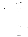
图3是表明依照本发明较佳实施例进行震动地震勘测的方法的流程图。Figure 3 is a flow chart illustrating a method of conducting a vibroseismic survey in accordance with a preferred embodiment of the present invention.
图4是说明依照本发明第一替代实施例,在图1所示的勘测中分离多个震动器中每一个与地震检波器中每一个之间的每条路径的大地响应的方法的流程图。4 is a flowchart illustrating a method of separating the ground response for each path between each of the plurality of vibrators and each of the geophones in the survey shown in FIG. 1 in accordance with a first alternative embodiment of the present invention .
图5是说明依照本发明第二替代实施例在图1所示的勘测中分离多个震动器中每一个与地震检波器中每一个之间的每条路径的大地响应的方法的流程图。5 is a flowchart illustrating a method of separating the ground response for each path between each of the plurality of vibrators and each of the geophones in the survey shown in FIG. 1 in accordance with a second alternative embodiment of the present invention.
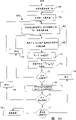
图6a和6b是说明根据本发明较佳实施例从分离过程结果产生地震勘测的另外两种方法的流程图。Figures 6a and 6b are flowcharts illustrating two other methods of generating a seismic survey from the results of the separation process in accordance with a preferred embodiment of the present invention.
图7a和7b分别是根据传统相位分离技术和根据本发明较佳实施例产生的一示范勘测的地震轨迹。Figures 7a and 7b are seismic traces of an exemplary survey produced according to conventional phase separation techniques and according to a preferred embodiment of the present invention, respectively.
图8是说明根据本发明另一实施例从分离过程结果中产生地震勘测的方法的流程图。8 is a flowchart illustrating a method of generating a seismic survey from the results of a separation process according to another embodiment of the invention.
图9是根据图8中所示的本发明实施例说明本方法所使用的逆过程的详细流程图。FIG. 9 is a detailed flowchart illustrating the inverse process used in the method according to the embodiment of the present invention shown in FIG. 8 .
图10是说明根据本发明的较佳实施例,在分离过程前进行的将记录数据变换到频域的另一替代方法的详细流程图。Figure 10 is a detailed flowchart illustrating an alternative method of transforming recorded data into the frequency domain prior to the separation process in accordance with the preferred embodiment of the present invention.
具体实施方式Detailed ways
首先参考图1,图中示出依照本发明的较佳实例正在进行两维(2-D)震动地震勘测的大地截面。以下的描述将针对大地的陆上勘测,当然应当明白,本发明也可用于海中地震勘测。Referring first to FIG. 1, there is shown a cross-section of the earth through which a two-dimensional (2-D) seismic seismic survey is being conducted in accordance with a preferred embodiment of the present invention. The following description will be directed to onshore surveys of the earth, it being understood, of course, that the invention may also be used in marine seismic surveys.
在图1所示的示范勘测中,将四个震动器VA至VD放在大地表明S。震动器V是一般的震动源,如安装在卡车上的这种震动器。传统震动器V的例子有1991年3月19日颁发的第5000285号美国专利中所描述的,该专利已转让给大西洋里奇菲尔德公司,这里引作参考;另一方面可以采用其它的震动地震勘测性能传统震动器。此外,也可以采用以编码方式产生地震能量的其它类型的致动器代替震动器V。在这个示范勘测中,震动器VA至VD相互靠近,但是隔开一段短距离。相邻震动器V之间的距离根据勘测设计而定,但是通常在40英尺的量级上。此外,在图1所示的两维示范勘测中,示出的震动器VA至VD是相互共线的。为了三维测量,震动器V可以按照非共线方式放在勘测区中。此外,无论是两维勘测还是三维勘测,对于图1所示位置中的震动器V进行所需次数的扫描后,将震动器V移动到勘测区的不同位置,以同样的方式激励。In the exemplary survey shown in Figure 1, four vibrators V A through V D are placed on ground surface S. The vibrator V is a general vibration source, such as this vibrator mounted on a truck. An example of a conventional vibrator V is described in U.S. Patent No. 5,000,285, issued March 19, 1991, assigned to Ridgefield Atlantic Corporation, which is incorporated herein by reference; alternatively other vibrating seismic Survey performance of traditional shakers. In addition, instead of the vibrator V, other types of actuators that generate seismic energy in an encoded manner may also be used. In this exemplary survey, vibrators VA through VD are close to each other, but separated by a short distance. The distance between adjacent vibrators V depends on the survey design, but is typically on the order of 40 feet. Furthermore, in the two-dimensional exemplary survey shown in Figure 1, the vibrators V A through V D are shown collinear with each other. For three-dimensional measurement, vibrators V can be placed in the survey area in a non-collinear manner. In addition, no matter it is two-dimensional survey or three-dimensional survey, after the vibrator V in the position shown in Fig. 1 is scanned for the required number of times, the vibrator V is moved to different positions in the survey area and excited in the same way.
在本发明的这个实施例中,敏感器5与每个震动器V以及震动分离系统10相连接;敏感器5检测震动器V的运动或力,给震动分离系统10产生一个对应于其有关的震动器V传给大地的实际源能量的信号。每个敏感器5可以是一个安装在震动器V反作用质量块或底板上或是直接与大地表面邻接的加速度计、测量震动器V激发腔体中压差的传感器、附着在震动器V底板上的负载单元、或是测量震动器V实际输出的其它传统传感器。由敏感器5进行的测量通常是实际震动的最小相位相对值,因此代表了由有关震动器V传给大地的实际源震动。In this embodiment of the invention, a
还是如图1的勘测所示,在与震动器V间隔一定距离的勘测区中,在大地表面S上设置地震检波器G1至G5。地震检波器G具有传统的结构,与传统震动地震勘测中通常采用的一样;另一方面,当然根据具体的勘测位置(陆上或海上)和能量类型,可以采用其它的传统检测器代替地震检波器G。此外,在震动地震勘测中,通常采用5个以上的多个地震检波器G;为简便起见,图1中仅仅示出5个地震检波器G。另外,图中示出的这5个地震检波器G相互共线,地震检波器G也可以按照非共线的排列结构而排列,或者根据勘测设计和所需结果,地震检波器G按照行列阵列的形式排列。地震检波器G直接的间隔可以很小,如在15至40英尺的量级。震动器V与地震检波器G组之间的距离根据具体勘测情况以及震动器V通过勘测区的滚降而改变。确实,在某些地震检波器G以阵列排列的勘测中,在勘测中震动器V实际上可以几次位于地震检波器阵列的区域中。As also shown in the survey of FIG. 1 , geophones G 1 to G 5 are arranged on the surface S of the earth in the survey area at a distance from the vibrator V. As shown in FIG. The geophone G is of conventional construction, as is commonly used in conventional vibro-seismic surveys; on the other hand, of course, depending on the specific survey location (onshore or offshore) and energy type, other conventional detectors may be used instead of geophones Device G. In addition, more than five geophones G are usually used in seismic surveying; for simplicity, only five geophones G are shown in FIG. 1 . In addition, the five geophones G shown in the figure are collinear with each other, and the geophones G can also be arranged in a non-collinear arrangement structure, or according to the survey design and the required results, the geophones G are arranged in a row-column array arranged in the form. The spacing between geophones G can be very small, such as on the order of 15 to 40 feet. The distance between the vibrator V and the set of geophones G varies according to the specific survey conditions and the roll-off of the vibrator V through the survey area. Indeed, in some surveys where geophones G are arranged in arrays, vibrators V may actually be located in the region of the geophone array several times during the survey.
正如图1所示,震动能量从每个震动器V传播到在勘测区中的地震检波器G。每个地震检波器G实际接收到的震动由于受到与震动器V与地震检波器G之间震动路径地质特性相对应的传递函数h的影响,将依赖于每个震动器V给出的输入震动信号。通过震动能量被地质结构的折射和反射将可确定这一传递函数h。以地震检波器G1为例,如图1所示,各个传递函数hA至hD是由大地给出的,对应于一端为震动器VA至VD、另一端为地震检波器G1的四条不同路径。因此,传递函数hA对应于震动器V1与地震检波器G1之间路径上的大地响应,它包括大地上层(如层2)中的折射效应和地下各层之间界面(如2、4层之间的界面I)的反射效应。大地的这两种物理效应引起地震检波器G1接收到的震动能量延迟以及与震动器VA传给大地的震动能量有所改变。因此,传递函数hA对应于当与源震动波形卷积时(在时域中)或者当与源震动频谱相乘时(在频域中)产生地震检波器G1记录信号的函数,正如本领域众所周知的。As shown in Figure 1, seismic energy propagates from each vibrator V to a geophone G in the survey area. The actual vibration received by each geophone G will depend on the input vibration given by each vibrator V due to the influence of the transfer function h corresponding to the geological characteristics of the vibration path between the vibrator V and the geophone G Signal. This transfer function h will be determined by the refraction and reflection of seismic energy by geological formations. Taking the geophone G 1 as an example, as shown in Fig. 1, each transfer function h A to h D is given by the earth, corresponding to vibrators V A to V D at one end and geophone G 1 at the other end four different paths. Therefore, the transfer function h A corresponds to the ground response on the path between the vibrator V1 and the geophone G1 , which includes the refraction effect in the upper layer of the earth (such as layer 2) and the interface between the subsurface layers (such as 2, Reflection effects at the interface I) between the 4 layers. These two physical effects of the earth cause the vibration energy received by the geophone G 1 to be delayed and the vibration energy transmitted to the earth by the vibrator V A to be changed. Thus, the transfer function h A corresponds to the function that produces the recorded signal of geophone G1 when convolved with the source shock waveform (in the time domain) or when multiplied with the source shock spectrum (in the frequency domain), as in this Well known in the field.
除了大地根据源震动产生的这些反射和折射效应以外,传递函数h还包括检测点(即敏感器5置于特定震动器V上的位置)与大地表面之间存在的相应震动V的动力学效应。例如,如果敏感器5作为测量震动器VA激发腔体中差压的传感器,传递函数hA还将包括通过监测差压测量源震动中不准确度的效应。由于这些动力学通常是最小相位效应,然而,如下所述,在接下来的滤波和处理中能够轻易地去除这些不准确性。In addition to these reflection and refraction effects of the ground in response to source vibrations, the transfer function h also includes the dynamic effects of the corresponding vibrations V existing between the detection point (i.e. the position where the
正如将要详细描述的,在震动勘测中利用同时进行多次扫描提供勘测所需时间的缩短,但是,对于进行的每一次扫描,导致每个地震检波器G记录一条根据每个震动器V提供震动能量的复合地震记录。地震检波器G记录的地震记录被存入震动分离系统10,由其进行分析。As will be described in detail, the use of simultaneous multiple scans in seismic surveys provides a reduction in the time required for the survey, but, for each scan taken, results in each geophone G recording a Composite seismic records of energy. The seismic records recorded by the geophones G are stored in the
现在参考图2,根据本发明的较佳实施例,用于分析震动器V和地震检波器G所记录地震震动的震动分离系统10,从每个地震检波器G中分离出每个震动器V对记录的地震信号的贡献。如图2所示,本发明较佳实施例的系统包括震动分离系统计算机24。系统计算机24可以用任何普通个人计算机或工作站来实现,较佳地采用基于UNIX的工作站,如Sun Microsystems公司提供的SPARC工作站,或是以独立方式或是作为网络配置的一部分来实现。根据本发明的较佳实施例,系统计算机24主要在图形显示器27上或是另外通过打印机28给出输出;进一步在另外实施例中,系统计算机24可以将以下所述的分析结果存在磁盘存储装置29中,供以后使用和进一步分析。给系统计算机24设置键盘26和点操作装置(例如,鼠标器、跟踪球等)25,以便能够进行交互操作。系统计算机24能够与磁盘存储装置,包括网络上的外部硬盘存储器和软磁盘驱动器进行通讯。正如图2所示,震动分离系统10既可以位于远离勘测区的数据中心,另一方面(较佳地)也可以位于勘测现场,提供对勘测结果的实时分析。Referring now to FIG. 2, a
如图2所示,设置记录单元21、23,记录勘测的震动信号。在这个例子中,记录单元23接收震动器V上加速度计的时域电信号,而记录单元21接收地震检波器G的时域电信号。记录单元21、23与磁盘存储装置30(如果需要,或者通过系统计算机)通讯,将震动器V和地震检波器G的电信号转变为数字数据,存储在磁盘存储装置30上。照此,记录单元21、23具有本领域人员熟知的普通结构。在本发明的这个实施例中,系统计算机24能够从一个或多个磁盘存储装置30中对代表检测到震动的存储数据进行检索。虽然图2示出磁盘存储装置30直接与系统计算机24连接,也可以设想,磁盘存储装置30可以通过局域网或是通过遥控进行存取。此外,虽然磁盘存储装置29、30是作为分别的装置示出的,当然在适当的时候也可采用单个的磁盘存储装置来存储任何的和所有的测量数据。As shown in FIG. 2 , recording units 21 and 23 are provided to record the surveyed vibration signals. In this example, the recording unit 23 receives the time-domain electrical signal of the accelerometer on the vibrator V, while the recording unit 21 receives the time-domain electrical signal of the geophone G. The recording units 21 , 23 communicate with the disk storage device 30 (or via the system computer if necessary), and convert the electrical signals of the vibrator V and the geophone G into digital data for storage on the disk storage device 30 . As such, the recording units 21, 23 have a common structure well known to those skilled in the art. In this embodiment of the invention, system computer 24 is capable of retrieving stored data representative of detected shocks from one or more disk storage devices 30 . Although FIG. 2 shows the disk storage device 30 directly connected to the system computer 24, it is contemplated that the disk storage device 30 could be accessed through a local area network or by remote control. Furthermore, while the disk storage devices 29, 30 are shown as separate devices, of course a single disk storage device could be used to store any and all of the measurement data, as appropriate.
现在参考图3并结合图1和2,将详细描述根据本发明较佳实施例进行震动地震勘测和分析其结果的方法。图3的方法将针对图1所示的震动器V和地震检波器G单一布局而描述,当然将会明白,对于整个勘测区上的震动器V和地震检波器G的多种布局通常可以重复应用和执行图3所述的方法。照此,图3所示方法中数据处理部分既可以实时(即在进行下一位置的勘测前对每个布局的信息进行处理)进行也可以在完成整个勘测区的数据获取后接下来进行批处理操作。Referring now to FIG. 3 in conjunction with FIGS. 1 and 2, a method of conducting a vibroseismic survey and analyzing the results thereof according to a preferred embodiment of the present invention will be described in detail. The method of Figure 3 will be described for the single arrangement of vibrators V and geophones G shown in Figure 1, although it will be understood that it can generally be repeated for multiple arrangements of vibrators V and geophones G over the entire survey area The method described in FIG. 3 is applied and executed. As such, the data processing part in the method shown in Figure 3 can either be performed in real time (that is, the information of each layout is processed before the survey of the next location) or it can be performed in batches after the data acquisition of the entire survey area is completed. Processing operations.
根据本发明的较佳实施例,过程32通过同时激励震动器V进行第一次扫描而开始勘测,在这一步中,每个震动器V使大地在一段频率范围下震动。根据所需勘测类型,可以由任何已知技术确定震动器V扫描的特定频率。典型地,频率上扫描或下扫描将产生震动波形V(t),在线性情况下为:
因此,过程32以传统方式按照所需方法激励震动器V扫描。在过程34中,由勘测中震动器V的敏感器5还有每个地震检波器G二者在时域中记录震动。记录单元21、23在适当的时候(或是在下一次扫描前或是在完成所有扫描后)将记录的震动信号传送到震动分离系统10中的磁盘存储装置30,完成过程34。正如本领域众所周知,存储的震动信号将是时域中敏感器5和地震检波器G接收的模拟震动的一系列数字取样值。Thus,
然后进行决断35,确定勘测中在震动器V对地震检波器G的特定位置上是否要进行附加扫描,在这种情况下,在过程36中以传统方式调节下一次扫描的扫描编码。然后,对于其余扫描重复过程32、34。根据本发明的第一实施例,进行扫描的次数(即经过过程32、34的次数)等于勘测中震动器V的数目。对于图1的例子而言,这里采用四个震动器VA至VD,进行四次扫描。A
完成所需次数的扫描,震动分离系统10,具体是指系统计算机24在过程38中根据震动器V记录的信号以及地震检波器G记录的信号,对记录的震动信号进行傅里叶变换,将存储的时域表示变换为频域的数字表示。过程38中采用的傅里叶变换技术是传统技术,通常称为离散傅里叶变换(DFT)或快速傅里叶变换(FFT)。然后把过程38的结果存入震动分离系统10的存储器,或是在系统计算机24的随机存取存储器中或是在磁盘存储装置30中。Complete the required number of scans, the
在一定的情况下,根据扫描编码,也可以对信号数据进行压缩,以便于进一步处理。现在参考图10,过程38’不仅将记录的信号变换到频域而且还对信号数据进行压缩,现在将说明这种压缩。过程38’是过程38的另一个实施例,在对多次扫描进行相互相位编码的情况中,它是特别有用的。Under certain circumstances, according to the scan coding, the signal data can also be compressed for further processing. Referring now to Figure 10, process 38' not only transforms the recorded signal into the frequency domain but also compresses the signal data, which compression will now be described. Process 38' is another embodiment of
过程38’从过程138由系统计算机24从存储器中检索震动器V的导频信号开始;由于在这种情况中对扫描进行相位编码,对于一次次扫描,除了相移外,加到震动器V上的导频信号是互相相同的。然后,对于单个记录信号Ri进行过程140,该信号或是一个地震检波器G记录的信号或是一个震动器V上敏感器5监测的信号,将记录信号Ri与过程138中检索到的导频信号进行相关。根据传统技术进行过程140相关。然后在过程142中用系统计算机24框出所需“监听”时间内的这些相关结果,以便可以放弃关心范围以外时间的数据。然后,在过程144中,系统计算机24对框出的记录信号Ri的相关结果进行DFT或FFT,将这些相关结果变换到频域中。决断145确定是否继续对附加记录信号Ri进行处理(包括地震检波器G记录的信号以及震动器V上敏感器5记录的这些信号二者);如果是,增加指数i并控制返回到相关过程140。完成过程144对每条记录信号Ri的相关和框出结果的FFT后,完成过程38’。Process 38' begins at
于是,根据以下所述的方法,任选过程38’能够大大地降低系统计算机24处理的数据量。过程38’的结果是导频信号和测量记录之间相关性的FFT,仅限于关心的时间窗口。此外,在过程之前进行这个压缩,因此,大大地提高了这里所述分离方法的效率。Thus, the optional process 38' can greatly reduce the amount of data processed by the system computer 24 according to the methods described below. The result of process 38' is an FFT of the correlation between the pilot signal and the measurement record, limited to the time window of interest. Furthermore, this compression is performed prior to the process, thus greatly increasing the efficiency of the separation method described here.
本领域的专业人员将会看到,任选过程38’可以根据系统计算机24的配置以及扫描编码的类型以不同的方法对信号数据进行变换和压缩。例如,可以在频域中而不是在时域中进行过程140、142的相关和框出,在这种情况下,可以在完成过程144后进行过程140、142。对于本领域的专业人员而言从这一描述中显然易见,也可以进行其它类型的传统处理。Those skilled in the art will appreciate that the optional process 38' can transform and compress the signal data in different ways depending on the configuration of the system computer 24 and the type of scan coding. For example, the correlating and framing of
根据本发明的较佳实施例,在过程40中,根据过程38中产生的记录震动的频域表示,进行震动器V到地震检波器G每条路径的大地响应的分离。这个分离既利用地震检波器G的记录震动又利用震动器V检测的震动;这与包括相位编码分离的传统分离技术不同,它们是根据导频信号(即输入震动的理想表示)分离的。这使得本发明能够更准确地确定大地对震动的响应,在分离过程中计及了寄生噪声、非线性、耦合不完善、底板弯曲以及有关各个震动器的工作问题。此外,根据本发明较佳实施例的分离方法逐个频率地而不是象传统分离技术那样以与频率无关的方式确定每条路径上的大地响应。结果,本发明在分离过程中能够处理与频率有关的效应,包括谐波耦合以及其它动作。According to a preferred embodiment of the present invention, in
现在参考图4并结合图1,对于多个震动器V与一个地震检波器G之间的多个大地响应路径,进一步详细描述分离过程40;当然应当明白,对于勘测区中的每个地震检波器G,也可以进行这一过程。如图1所示,每一个震动器VA至VD产生震动,通过各条物理路径传给地震检波器G1。每条路径对应于一个响应,或传递函数hA至hD分别对应于地震检波器G1与震动器VA至VD之间的路径。不管采用的震动扫描类型,传递函数h当然表示大地对震动能量响应的贡献,包括反射和折射,因此在产生区域地震勘测以及确定地下界面位置和各种地质形成中是有用信息。Referring now to FIG. 4 in conjunction with FIG. 1 , the
对于四个源VA至VD的四次一组震动扫描,可以考虑把地震检波器G1记录的频域表示作为DFT中每个频率的一个方程式系,表示为:R1=A1·hA+B1·hB+C1·hC+D1·hDR2=A2·hA+B2·hB+C2·hC+D2·hDR3=A3·hA+B3·h8+C3·hC+D3·hDR4=A4·hA+B4·hB+C4·hC+D4·hD式中Rn是第n次扫描地震检波器G在规定频率下记录的复合频域表示系数,An是第n次扫描震动器VA测量的在规定频率下的源震动系数,Bn是第n次扫描震动器VB测量的在规定频率下的源震动系数,以此类推。当然,在这个系中每个系数是复数。由于对于每一次扫描,在过程34中已经记录了震动器V上震动,对于每一次扫描已经获得地震检波器G1上地震记录,因此它们是已知的,上述系具有四个未知数的四个方程式,由此可以确定规定频率的传递函数hA至hD的解。For a group of four vibration scans of four sources V A to V D , the frequency domain representation recorded by geophone G 1 can be considered as an equation system for each frequency in DFT, expressed as: R 1 =A 1 · h A +B 1 h B +C 1 h C +D 1 h D R 2 =A 2 h A +B 2 h B +C 2 h C +D 2 h D R 3 =A 3 ·h A +B 3 ·h 8 +C 3 ·h C +D 3 ·h D R 4 =A 4 ·h A +B 4 ·h B +C 4 ·h C +D 4 ·h D where R n is the complex frequency domain expression coefficient recorded by the geophone G at the specified frequency in the nth scan, A n is the source vibration coefficient at the specified frequency measured by the vibrator V A in the nth scan, and B n is the nth scan The source vibration coefficient at the specified frequency measured by the sub-scan vibrator V B , and so on. Of course, in this system each coefficient is complex. Since for each scan the vibrations on vibrator V have been recorded in
可以用矩阵形式将上述的系表示为:
以下的描述将源震动表示的逆矩阵称为[S-1]。The following description refers to the inverse matrix of the source vibration representation as [S −1 ].
如上所述,在扫描中通常利用相位编码。在这种情况下,每个源震动表示An、Bn、Cn、Dn为复数。以上述的传统相位编码为例,理想的输入波形(即扫描的波形是严格地由震动器V产生的)将具有下表所给出的相位关系(以度表示):As mentioned above, phase encoding is usually utilized in scanning. In this case, each source vibration represents A n , B n , C n , D n as complex numbers. Taking the conventional phase encoding described above as an example, an ideal input waveform (i.e. the scanned waveform is strictly generated by the vibrator V) would have the phase relationship (expressed in degrees) as given in the following table:
震 动 器vibrator
A B C D扫描1 0 90 90 180扫描2 90 0 180 90扫描3 90 180 0 90扫描4 180 90 90 0
在这种理想情况下,矩阵[S]由下式表示,式中i是虚数指示(即-1的平方根,对应于90°相移):
然而,已经观察到,由一般的震动器传给大地的实际震动能量略微偏离理想的输入波形。这是由于震动器V工作中的非线性使所需波形从控制信号到实际震动的不良转换、震动器V与大地的不良耦合、底板弯曲以及震动器V中的声耦合造成的。此外,已经观察到,传统的震动器V在一次次扫描中其输出不是完全重复的。当采用理想波形的相位矩阵时,这些效应中每一种都会把误差引入到分离和分析过程中。However, it has been observed that the actual vibration energy delivered to the earth by typical vibrators deviates slightly from the ideal input waveform. This is due to non-linearities in the operation of the vibrator V causing poor conversion of the desired waveform from the control signal to the actual vibration, poor coupling of the vibrator V to ground, base plate bending, and acoustic coupling in the vibrator V. Furthermore, it has been observed that the output of a conventional vibrator V is not perfectly repeatable from scan to scan. Each of these effects introduces errors into the separation and analysis process when using a phase matrix of ideal waveforms.
于是,如上所述,根据本发明的这个实施例,过程40中采用的矩阵[S]及其逆矩阵[S-1]是基于震动器V的实际震动测量结果,例如用图1中敏感器(加速度计)5以及可用于测量震动器V实际工作的这类其它传统传感器获得的。此外,由于许多畸变效应(尤其是谐波效应)与震动的频率有关,依照本发明较佳实施例的方法,利用在震动器V和地震检波器G二者上测得的复数频域系数,分别根据范围内的离散频率进行工作。Thus, as mentioned above, according to this embodiment of the invention, the matrix [S] and its inverse matrix [S -1 ] employed in
参考图4,照此分离过程40从过程42开始,在过程42中,确定第一频率fK下的逆复数矩阵[S-1]。系统计算机24通过从存储器检索震动器V在频率fK下的频域震动测量结果的幅度和相位,确定这个频率fK下的逆矩阵,接着利用传统的数值分析技术确定原始矩阵[S]的行列式和余因子,产生逆矩阵[S-1]的系数。从以下,逆矩阵[S-1]是基于过程32中震动器V在产生震动能量中的实际动作。Referring to Figure 4, as such the
例如,如果在第一次扫描中震动器VA完全未能工作,如果震动器VD在第四次扫描中具有相位和幅度误差,对于给定的频率fK,对于上述相位编码的四次一组扫描,矩阵[S]将以下式出现:
根据本发明的较佳实施例,接着进行过程45,从过程42建立逆矩阵[S-1]的质量值。对于这里所述的分离过程30而言,过程45是任选的,相信对分辨这样的频率是有用的,即在这些频率下,解是如此不稳定以致对这里所述的频域处理打折扣。例如,在扫描范围以外的频率上,频率响应是乎是不可靠的,因为在这些频率上谐波效应是很严重的。在这里所述的过程45的例子中,确定质量值,作为频率fK下传递或响应函数的结果能够与之相乘的加权因子(动作好的操作接收最大加权因子1)。另一方面,可以用质量因子导出施加到分离最终结果的滤波器,或作为现场质量控制测量,以致如果质量值太低,可以重新进行一次或多次扫描。According to a preferred embodiment of the present invention,
如图4所示,通过计算频率fK下的矩阵[S]的本征值λ,也称为特征值,过程44起动过程45。正如本领域人员所熟知的,根据本发明的这一实施例,复数矩阵,如矩阵[S]的本征值本身就是复数。已经观察到,对于矩阵[S]特性差的这些情况,即当矩阵[S]的本征值λ中的一个或多个很小时的情况,大地响应函数h的确定是不可靠的。因此,根据本发明这个实施例,决断43是确定质量值QV,该值与矩阵[S]本征值的大小有关,尤其与最小本征值的大小有关。例如,质量值QV可以定义为下式:
根据本发明的较佳实施例,过程45(如果进行的话)之后,接下来进行过程47,确定勘测区中震动器VA至VD到地震检波器G的所有路径的传递函数hA至hD(在这个例子中)。可以依照不同替代技术进行过程47,现在将对此进行描述。According to a preferred embodiment of the present invention, process 45 (if performed) is followed by
如上所讨论的,以地震检波器G1为例,下面的矩阵方程式对应于给勘测区施加源能量:As discussed above, taking geophone G1 as an example, the following matrix equation corresponds to applying source energy to the survey area:
[R]=[S]●[h]式中[R]是四次扫描时地震检波器G1的地震记录集合,[S]是在四次扫描中由震动器VA至VD施加的源能量矩阵,[h]是传递函数矩阵。照此,由于通过过程34的测量,[R]和[S]是已知的,在过程42中找出逆矩阵[S-1],通过下列矩阵相乘,可以由过程47求解频率fk下的传递函数[h]:[R]=[S]•[h] where [R] is the set of seismic records of geophone G 1 in four scans, and [S] is applied by vibrators V A to V D in four scans source energy matrix, [h] is the transfer function matrix. As such, since [R] and [S] are known through the measurement of
[h]=[S-1]●[R][h] = [S -1 ] [R]
通过上述的系统计算机24能够方便地进行这个矩阵相乘,对于本专业人员而言将是显而易见的。It will be apparent to those skilled in the art that this matrix multiplication can be conveniently performed by the system computer 24 described above.
然后进行决断48,决定是否通过分离过程40继续对增大的频率进行分析。如果是,控制进到过程49,在这个过程中,将频率指数k增大到测量震动频域表示的下一个离散频率。当然,如果没有另外的频率要分析,控制进到图3的过程50。A
上面的方法采用传统相位编码方案,在该方案中,在每次扫描期间,在过程32中对每个震动器V进行激励。由于本发明的这个实施例考虑了在一定的扫描中失去震动器或震动器不工作,根据本发明的另一替代实施例,在过程32中每一次扫描期间有意地关闭一个震动器V或者不激励它。根据本发明的这个替代实施例,不必进行相位编码(即所有的震动是相互同相的)。于是,在本发明的这个替代实施例中,理想源震动矩阵[S](对于所有频率)则为:
再说,矩阵[S-1]的实际值将依赖于震动器V上测得的震动。除了采用不同的编码方案外,根据本发明这个实施例的方法,其余的部分按照如上所述的过程进行。Again, the actual value of the matrix [S -1 ] will depend on the vibrations measured on the vibrator V. Except for adopting different encoding schemes, according to the method of this embodiment of the present invention, the rest of the process is performed as described above.
现在参考图5,将描述依照本发明另一替代实施例的分离过程40’。过程40’与上述的过程40类似,是确定震动器VA至VD到地震检波器G的所有路径的传递函数h。然而,根据过程40’,通过对基于该过程的方程式系的过指定并结合利用震动源上测得的实际震动,可增大确定大地响应的可靠性。Referring now to FIG. 5, a separation process 40' according to another alternative embodiment of the present invention will be described. Process 40', similar to process 40 described above, is to determine the transfer function h for all paths from vibrators VA through VD to geophone G. However, according to the process 40', the reliability of the determination of the ground response can be increased by over-specifying the system of equations based on the process in conjunction with the use of actual vibrations measured at the vibrating source.
在消除记录地震震动中噪声影响中,由本发明这个替代实施例获得的这个可靠性增加是特别有用的。众所周知,勘测中地震检波器G经常检测到与震动器V产生的震动能量无关的震动,或者会产生与任何震动无关的信号;这种无关震动或寄生信号通常被称为噪声,显然,它们降低了准确区分和分析所产生震动能量的勘测能力。The increased reliability obtained by this alternative embodiment of the invention is particularly useful in eliminating the effects of noise in recorded seismic vibrations. It is well known that the geophone G in the survey often detects vibrations unrelated to the vibration energy produced by the vibrator V, or produces signals unrelated to any vibrations; such extraneous vibrations or spurious signals are often called noise, and obviously, they reduce The ability to accurately distinguish and analyze the vibration energy generated.
因此,在通常意义上,可以考虑下式表示的多次扫描中第n次扫描的单个地震检波器G记录的复合地震记录Rn:Therefore, in a general sense, the composite seismic record Rn recorded by a single geophone G of the nth scan among multiple scans can be considered as follows:
Rn=An·hA+Bn·hB+Cn·hC+Dn·hD+Nn R n =A n h A +B n h B +C n h C +D n h D +N n
如前所述,Rn是第n次扫描的地震检波器G记录的复合频域表示,An是第n次扫描的震动器VA的源震动数据,Bn是第n次扫描的震动器VB的源震动数据,以此类推。此外,在这个方程式中有一个Nn项,表示噪声对扫描的贡献。由此可见,对于大地响应或传递函数h,由于存在该噪声项Nn,上式所表示的方程式系的解将变得复杂化。因此,降低记录的地震记录中噪声影响,提高震动地震勘测的准确度和分辨率是有用的。As before, R n is the composite frequency domain representation of the geophone G record for scan n, An is the source vibration data for vibrator V A for scan n, and B n is the vibration for scan n The source vibration data of the device V B , and so on. Additionally, there is an N term in this equation that represents the noise contribution to the scan. It can be seen that for the ground response or transfer function h, due to the existence of the noise term N n , the solution of the equation system represented by the above formula will become complicated. Therefore, it is useful to reduce the effect of noise in recorded seismic records and to improve the accuracy and resolution of seismic seismic surveys.
根据过程40’,该过程是上式分离过程的另一替代实施例,降低记录的地震记录中噪声影响。现已观察到,震动地震勘测中记录的噪声最主要的是所谓的随机噪声;换句话说,一次扫描中记录的噪声通常与以后各次扫描中记录的噪声不相关。正如现在说明的,过程40’利用记录的噪声的随机性消除它在多次扫描中的影响。According to process 40', which is another alternative embodiment of the above separation process, the effect of noise in the recorded seismic record is reduced. It has been observed that the noise recorded in vibroseismic surveys is predominantly so-called random noise; in other words, the noise recorded in one scan is generally uncorrelated with the noise recorded in subsequent scans. As now explained, the process 40' exploits the randomness of the recorded noise to cancel its effects over multiple scans.
首先,根据本发明的这个实施例,在过程32(图3)中必须进行多于勘测中震动器V个数的多次扫描。换句话说,必须对地震记录Rn的方程式系进行过指定。较佳地以某种方式,如上述的相位编码,对每个震动器VA至VD的能量进行编码;多出的这次扫描(即四个震动器的第五次扫描)可以简单地重复以前进行的一次扫描,或者代之以相位编码方案预计进行的第五次扫描。在图1所示的勘测中,激励四个震动器VA至VD,由下式表示五次扫描的过指定:First, according to this embodiment of the invention, more than the number of vibrators V in the survey must be scanned in process 32 (FIG. 3). In other words, the system of equations for the seismic record R n must be specified. The energy of each vibrator V A through V D is preferably encoded in some manner, such as phase encoding as described above; the extra scan (i.e., the fifth scan of the four vibrators) can be simply Repeat the previous scan, or substitute the fifth scan expected by the phase-encoding scheme. In the survey shown in Figure 1, four vibrators V A through V D are excited, and the five-sweep overspecification is expressed by:
R1=A1·hA+B1·hB+C1·hC+D1·hD+N1 R 1 =A 1 ·h A +B 1 ·h B +C 1 ·h C +D 1 ·h D +N 1
R2=A2·hA+B2·hB+C2·hC+D2·hD+N2 R 2 =A 2 ·h A +B 2 ·h B +C 2 ·h C +D 2 ·h D +N 2
R3=A3·hA+B3·hB+C3·hC+D3·hD+N3 R 3 =A 3 ·h A +B 3 ·h B +C 3 ·h C +D 3 ·h D +N 3
R4=A4·hA+B4·hB+C4·hC+D4·hD+N4 R 4 =A 4 ·h A +B 4 ·h B +C 4 ·h C +D 4 ·h D +N 4
R5=A5·hA+B5·hB+C5·hC+D5·hD+N5式中Nn项对应于方程式系中的记录噪声。假设噪声项Nn是随机的,在关心的频率上∑Nn=0,记录Rn表示为以下的系组:
[R]=[S]·[h][R]=[S]·[h]
然而,由于扫描次数大于震动器-地震检波器路径的数目(即矩阵[S]代表一个过指定的系),矩阵[S]不是正方矩阵。于是,必须经过几个步骤才能进行传递函数[h]的上述矩阵方程式的解。例如,可以在以上方程式的两边乘以转置矩阵[ST],得到下列方程式:However, because the number of scans is greater than the number of vibrator-geophone paths (ie, matrix [S] represents an overspecified frame), matrix [S] is not a square matrix. Then, the solution of the above matrix equation of the transfer function [h] must be performed through several steps. For example, the transpose matrix [S T ] can be multiplied on both sides of the above equation to obtain the following equation:
[ST][R]=[STS]·[h][S T ][R]=[S T S]·[h]
因此,利用矩阵[S]的“广义逆”可以求每条震动器路径的传递函数[h]的解,表示为:Therefore, the transfer function [h] for each vibrator path can be solved using the "generalized inverse" of the matrix [S], expressed as:
[h]=[STS]-1·[ST][R][h]=[S T S] -1 ·[S T ][R]
这些关系用在图5所示的分离过程40’中,现在将对此进行描述。分离过程40’从过程52开始,在这个过程中,系统计算机24对震动器V在频率fk下测得的震动的幅度和相位信息(即矩阵[S])进行检索;过程52进一步包括从矩阵[S]确定转置矩阵[ST]。众所周知,通过每个矩阵元的位置指数倒转(即行变成列)可以简单地进行过程52中转置矩阵[ST]的确定,由系统计算机24能够方便地进行转置矩阵的确定。较佳地,只要系统计算机24编制的程序在接下来的步骤中能以转置方式检索矩阵[S]的复数系数,在过程52中不必增加对转置矩阵[ST]的矩阵元的存储。These relationships are used in the separation process 40' shown in Figure 5, which will now be described. Separation process 40' begins with
接着进行过程54,在这个过程中,系统计算机24产生频率fk下的逆矩阵[STS]-1。较佳地,过程54首先进行矩阵相乘[ST]·[S],然后在系统计算机24的能力范围内通过一般的数值步骤,确定逆矩阵[STS]-1,如上所述,它涉及乘积矩阵[STS]的行列式和余因子的计算。如果需要那么可以进行任选过程56,它与上述的分离过程40中过程45相类似,是确定频率fk下勘测中进行的扫描正则性的加权因子指数(即“动作是如何好”)。正如针对过程45所述的,可以用这个加权因子调节这些频率下的勘测结果,这里,噪声、非线性、谐波或其它现象对该频率fk下的结果带来一定疑问。
过程54或过程56之后,根据具体情况,分离过程40’确定各个震动器V与地震检波器G1之间每条路径的大地响应,按照传递函数矩阵[h]给出的。这是在过程57中进行的,在该过程中,通过系统计算机24进行一般数值矩阵乘法运算,将复数逆矩阵[STS]-1加在每次扫描的地震检波器G1的记录上(即加到乘积矩阵上[ST][R])。于是,过程57的结果是,通过分离过程40’确定地震检波器G1对应于每条震动器-地震检波器路径的传递函数[h]集合。Following
当然,虽然以上所述的分离过程40’仅针对一个地震检波器G1,但是应当明白,对于勘测区中的每个地震检波器G在频率fk下都可进行过程40’。Of course, while the separation process 40' has been described above for only one geophone G1 , it should be understood that the process 40' can be performed at frequency fk for each geophone G in the survey area.
过程57之后,进行决断58,确定是否继续根据分离过程40’对增大的频率进行分离。如果是,频率指数k增大到频域数据中对应震动器V和地震检波器G检测到震动数据的下一个离散频率。然后对于该频率重复过程40’。一旦完成对所有的所需频率的分离(即决断58返回到“否”),控制进入到过程50,进行勘测数据的进一步处理。After
回过来参考图3,完成分离过程40或是40’,现在可以利用地震勘测中产生的每条震动器-地震检波器路径的分离的大地响应函数进行过程50。根据每条路径找出的传递函数和大地响应产生地震勘测结果的具体方法是本领域常用方法,根据地质专家的需要选择特定过程。Referring back to FIG. 3, having completed the
现在参考图6a和6b,详细描述根据上述的分离过程40、40’结果进行地震勘测的过程50的另外两个实施例。图6a和6b所示的过程50a和50b相互分别等同,图6a所示过程50a是在频域中进行的,图6b所示的过程50b是在时域中进行的。从以下的描述中显而易见,过程50a、50b在系统计算机24的能力之内。Referring now to Figures 6a and 6b, two further embodiments of a
首先参考图6a,先进行过程62,在这一步中选择分析用的特定地震检波器Gn;然后,过程64选择第一震动器Vi,因此选择了过程50a第一步中分析用的震动器Vi与地震检波器Gn之间的路径。然后进行过程66,在这个过程中,由系统计算机24从存储器中检索与震动器Vi与地震检波器Gn之间路径相对应的传递函数hin的系数,作为频域表示中的每个频率点。照此,检索过程66对传递函数hin复数系数的频域谱进行检索。如上所述,传递函数hin中的这些系数也可以包括上述过程45产生的加权因子或者被这些加权因子修改,以致如果监测到的源震动系数矩阵特征不好可以对特定频率下的系数进行某个程度的折算。Referring first to Fig. 6a,
在过程68中,频域系数hin与第一次扫描j中震动器Vi监测到的源震动的频域系数Ij相乘。过程68中这个相乘仅仅是传递函数hin中每个系数与扫描j监测到系数Ij集合中相同频率系数的点-点相乘。然后,过程70进行hin·Ij这个乘积的逆离散傅里叶变换,将这个结果变换到时域中。因此,过程70的结果是利用它们之间路径的传递函数hin,与地震检波器Gn上实际检测到的唯一基于震动器Vi源震动的震动相对应的震动的时域表示;因此,这个结果是实际检测到震动的理想表示,这里,将震动器Vi的贡献从其它震动器V的贡献中分离出来。In
然后进行过程72,通过这个过程,扫描j中用于驱动震动器Vi的导频信号与乘积hin·Ij的时域表示互相关。因此,过程72的结果是震动能量到达地震检波器Gn的时基指示,由此可导出反射界面的深度。当然,众所周知,通过将多条记录叠加(在这当中信号将得到加强,而随机噪声趋于抵消)可以消除随机噪声对这种时基记录的影响。于是,决断71确定是否继续对地震检波器Gn进行震动器Vi的附加扫描数据的分析;如果是,那么增大扫描指数(过程73)控制进行到过程68,在这个过程中,再次进行下一次扫描的传递函数hin与源震动Ij的乘积,重复以上的过程。
对于勘测中震动器Vi的所有次扫描,完成频域相乘(过程68)、逆DFT(过程70)和互相关(过程72)后,在过程74中系统计算机24将震动器Vi与地震检波器Gn之间能量的互相关记录叠加。因此,产生的叠加记录适合在传统地震勘测方法中使用,指示震动器Vi与地震检波器Gn之间产生的源震动的延时。After frequency-domain multiplication (process 68), inverse DFT (process 70), and cross-correlation (process 72) have been performed for all scans of vibrator V in the survey, system computer 24 in
如图6a所示,对于从每个震动器Vi到地震检波器Gn的能量可以重复这一过程,通过决断75确定是否对地震检波器Gn进行增加的震动器Vi的分析;如果是,增大震动器指数i(过程76),控制进行到过程66,重复对下一个震动器Vi的分析。如果对于地震检波器Gn已经进行了所有震动器V的分析,那么决断77类似地确定是否以上述方式对增加的地震检波器G进行分析;如果是,那么增大地震检波器指数n(过程78),控制返回到过程64,在这个过程中,对于下一个地震检波器Gn敏感到其产生能量的所有震动器V,重复上述过程。As shown in Fig. 6a, this process may be repeated for the energy from each vibrator Vi to geophone Gn , with
对勘测中所有震动器V和所有地震检波器G,在完成过程50a后,然后进行过程80,通过这个过程,按照所需方式安排地震勘测,就象通常对震动地震勘测那样。例如,过程80可以包括共深度点(CDP)收拢、正常时差(NMO)操作等,它们给出更便于地质专家使用形成的勘测数据。然后完成图3所示的勘测方法。After completion of
在上述的过程50a中,该方法中绝大部分是针对频域系数进行的。这种类型的运算尤其适合于对于装入数字信号处理器(DSP)的现代系统计算机24,因此,这种计算机特别地适于进行频域运算和逆DFT运算。然而,许多常规的系统计算机较为适合于时域运算,如卷积运算。图6b所示的过程50b较为适合于这种类型的计算机。在图6a和6b中,用相同标号表示过程50a中与过程50b中相同的步骤。In the above-mentioned
在图6b所示的过程50b中,与先前一样进行过程62、64、66,从而由系统计算机24从存储器中检索所有频率下分析用的对应震动器Vi与地质检波器Gn路径的hin传递函数系数。在过程66中检索到的系数已经被上述过程45产生的加权因子修改,对系统中特性差的这些频率上的系数进行折算。然后在过程82中,系统计算机24进行传递函数系数hin的逆DFT,产生一系列时域系数δin代表大地对震动地震能量的时域脉冲响应。In
对于第一次扫描j,进行过程84,在这一步中,将脉冲响应序列δin与扫描j中震动器Vi监测到的源震动的时域记录Ij(t)进行卷积。正如以上针对图3所讨论的,在过程34中记录敏感器5监测到源震动,作为时域信号,然后通过过程38的DFT,将其转换到频域中。因此,如果把过程50b当作分析过程,保留过程34的源震动的时域记录,供过程84之用是较佳的。当然,如果未保留时域表示(但是已经存储了频域转换表示),在进行过程84的卷积前,通过逆DFT运算可获得时域信号Ij(t)。众所周知,脉冲响应序列δin(t)与扫描j中震动器Vi的源震动Ij(t)的时域卷积将产生一个对应于震动器Vi对第j次扫描中地震检波器Gn记录震动的分离贡献的时域表示。For the first scan j,
根据图6b所示的过程50b,然后将过程84的卷积乘积与第j次扫描中用于驱动震动器Vi的导频信号进行互相关。以在过程50a中所述的方式进行这个互相关,产生震动能量到达地震检波器Gn的时基指示,在推导反射界面深度中它是有用的。According to
与图6a所示过程50a的情况一样,对于一对震动器-地震检波器Vi,Gn进行的每一次扫描,重复过程68、70、72,接着将互相关记录叠加,去除随机噪声的影响,结束过程50b。然后,对于勘测中所关心的每一个震动器V和每一个地震检波器G进行上述过程,接着根据所需格式、收拢和时差校正安排过程80中的勘测。As in the case of
根据过程50a、50b中任一过程,从每个地震检波器G记录的复合震动中分离各震动器V的贡献,从而对地震勘测作出准确判定。具体说,根据本发明这个实施例的分离震动信号的能力大大改善了勘测的分辨率,因为,能够对各个震动器与地震检波器之间的路径进行分析,而不再象现有技术的通常情况那样,限于对整个源阵列与每个地震检波器之间路径的广义分析。当然,分辨率的提高将会改善地震勘测的准确度及其对比较小但是很重要的地质特征的灵敏度。According to either of the
现在参考图7a和7b,介绍震动地震勘测的一个例子。图7a示出从排成一行距震动器位置VA不同距离的地震检波器上记录的一系列轨迹。在图7a中,每一条垂直轨迹对应于一个地震检波器的记录,图中以常规方式显示,图中时轴从图的上部到下部,自震动器位置VA的距离从右到左增大。图7a所示的例子表明在同时使四个震动器V工作并根据本发明背景中所给出的表进行相位编码的勘测中对震动器VA的能量贡献。然后采用相对该相位编码技术的相位分离的传统方法产生图7a的曲线。Referring now to Figures 7a and 7b, an example of a vibroseismic survey is presented. Figure 7a shows a series of traces recorded from geophones lined up at different distances from vibrator position VA . In Fig. 7a, each vertical trace corresponds to a geophone record, shown in a conventional manner in the figure, where the time axis runs from the upper part of the figure to the lower part of the figure, and the distance from the vibrator position V A increases from right to left . The example shown in Figure 7a shows the energy contribution to vibrator V A in a survey with four vibrators V operating simultaneously and phase encoded according to the table given in the Background of the Invention. The curve of Figure 7a is then generated using the conventional method of phase separation relative to this phase encoding technique.
现在参考图7b,该图示出图7a的勘测中震动器VA的贡献,这里,根据本发明的较佳实施例进行震动器VA贡献的分离。然后,在每个频率下对每个地震检波器,通过将(震动器VA)传递函数hA与震动器VA测得的源震动相乘,接着对其结果进行逆DFT产生时域轨迹,产生图7b所示的轨迹。Referring now to FIG. 7b, which shows the vibrator VA contribution in the survey of FIG. 7a, where separation of the vibrator VA contribution is performed in accordance with a preferred embodiment of the present invention. Then, for each geophone at each frequency, time-domain traces are generated by multiplying the (vibrator V A ) transfer function h A by the source vibration measured at vibrator V A , followed by inverse DFT of the result , yielding the trajectory shown in Fig. 7b.
将图7a与图7b进行比较,表明通过上述的本发明较佳实施例得到的改善。首先,图7b区域88b所示的首次到达时间比图7a区域88a所示的首次到达时间规则和一致得多,因此,当利用近表面层中折射波的速度进行静态校正时,改善了计及近表面层厚度偏差的能量。图7a、7b中区域90a、90b分别对应正在发生反射情况(即检测到地下界面的时间和距离)的勘测部分;比较图7a、7b,表明在这个情况上区域90b的保真度大大高于区域90a的保真度,方便了反射情况的分析和识别。此外,对图7a与7b之间区域91a与91b、92a与92b分别进行比较,表明本发明的较佳实施例通过降低更深勘测部分的高频噪声而改善勘测结果。Comparing Figure 7a with Figure 7b shows the improvement achieved by the preferred embodiment of the invention described above. First, the times of first arrival shown in region 88b of Fig. 7b are much more regular and consistent than those shown in region 88a of Fig. The energy of the near-surface layer thickness deviation. Regions 90a and 90b in Figures 7a and 7b respectively correspond to the portion of the survey where reflection conditions (i.e. the time and distance at which the subsurface interface is detected) are occurring; comparison of Figures 7a and 7b shows that in this case the fidelity of region 90b is much higher than The fidelity of the region 90a facilitates the analysis and identification of reflection conditions. Furthermore, a comparison of regions 91a and 91b, 92a and 92b between Figures 7a and 7b, respectively, shows that the preferred embodiment of the present invention improves survey results by reducing high frequency noise in deeper survey portions.
根据本发明的另一实施例,可以执行过程50,通过1995年5月5日提交的S.N.08/435940申请中所述的逆过程,应用频域传递函数[h],该申请已转让给美孚石油公司,美孚石油公司允许这里引作参考。According to another embodiment of the present invention,
根据这个方法,频域中的每个传递函数hv-g(f)(这里v和g表示指定震动器-地震检波器路径的震动器和地震检波器指数)对应于反射率函数E乘以最小相位函数M。最小相位函数M加入了大地的一些影响(例如,风化的近表面层)以及在产生输入震动能量中的震动器V的阻抗。According to this approach, each transfer function h vg (f) in the frequency domain (where v and g denote the vibrator and geophone indices specifying the vibrator-geophone path) corresponds to the reflectivity function E times the minimum phase function M. The minimum phase function M incorporates some influence of the earth (eg, weathered near-surface layers) and the impedance of the vibrator V in generating the input shock energy.
如上讨论的,根据本发明的较佳实施例,由敏感器5测得直接来自震动器V的与大地表面中产生的有效力有关的最小相位信号。照这样,在这个分析过程中采用实际信号代替现有技术通常采用的理论导频信号。正如这里引用的1996年8月27日颁发的第5550786号美国专利中所述,以不必知道实际施加的力的方法进行震动运动的记录和对记录地震数据的处理。唯一重要的因素是测量量直接与施加的实际力成正比。用这种方式,能够通过除法消除实际力。As discussed above, in accordance with the preferred embodiment of the present invention, the minimum phase signal from the vibrator V is measured by the
根据本发明的这个实施例发现,震动器V上敏感器5测得的运动与通过频域中最小相位传递函数传到大地中的实际输出力或信号有关。因此,在频域中,测得的输出力信号S对应于震动器真实输出U与最小相位传递函数T的乘积:According to this embodiment of the invention it is found that the motion measured by the
S=U·T式中:·代表频域中的相乘。传递函数T是真实的震动器输出U与测得的震动器运动U关联的最小相位、因果、线性的系。在这个方程式中最小相位传递函数T和实际输出源的力U都是未知的。 S = U·T where: · Represents multiplication in the frequency domain. The transfer function T is the minimum phase, causal, linear relationship between the true vibrator output U and the measured vibrator motion U. Both the minimum phase transfer function T and the actual output source force U are unknown in this equation.
在频域中用实际源的力U的时间导数与大地反射率E的卷积表示地震检波器G检测到的地震记录R,如下式所示:R=jω·U·E式中:R代表测得的地震数据,jω代表时间导数,E代表大地反射率函数。In the frequency domain, the seismic record R detected by the geophone G is represented by the convolution of the time derivative of the force U of the actual source and the reflectivity E of the ground, as shown in the following formula: R = jω·U·E where: R represents For the measured seismic data, jω represents the time derivative, and E represents the earth reflectance function.
通过利用最小相位带通滤波器的反向滤波,能够方便地计算R/S比。这个比值从下式的方程式中消除未知的U、源输出力:
现在用R/S表示地震图,与最小相位函数jω/T进行卷积(在时域中),该图构成大地反射率E的所需答复。最小相位函数的特点是它们的导数和它们的倒数也是最小相位。用最小相位的反卷积能够对地震图进一步进行处理,以获得E,频域中大地的反射率脉冲响应。本质上,R/S地震图是频带限制的脉冲地震图。它是与大地响应有关的因果和最小相位。这种方法的准确度高,因为已经不依赖于实际的、还是未知的源震动运动。Now denoting the seismogram by R/S, convolved (in time domain) with the minimum phase function jω/T, this map constitutes the desired answer for the reflectivity E of the earth. Minimum phase functions are characterized in that their derivatives and their reciprocals are also minimum phase. The seismogram can be further processed by deconvolution with minimum phase to obtain E, the reflectivity impulse response of the ground in the frequency domain. Essentially, R/S seismograms are band-limited pulsed seismograms. It is causal and minimal phase related to the earth's response. The accuracy of this method is high because it is no longer dependent on the actual, still unknown, source vibration motion.
参考以上所讨论的方法,主要是针对过程47,系统计算机24进行矩阵运算,提供[R]/[S];换句话说,这个比是[S-1]·[R],或者传递函数[h]。如上所述,传递函数[h]是在每个频率fk下从震动器V敏感器5测量结果的源震动逆矩阵[S-1]与基于地震检波器G记录的震动的矩阵[R]的乘积:With reference to the methods discussed above, primarily for
[h]=[S-1]●[R][h] = [S -1 ] [R]
在这个例子中,对于频率fk下震动器VA至VD与地震检波器G1之间所有四条路径,这个乘积产生频率上的传递函数h的矩阵[h]。实际上,对记录R进行分离,提供每个地震检波器对于各个震动器V的轨迹。当然,如上所述,对于勘测中所关心的每一个地震检波器G可进行类似的操作。In this example , this product yields a matrix [h] of transfer functions h over frequency for all four paths between vibrators VA through VD and geophone G1 at frequency fk. In effect, the records R are separated, providing traces for each vibrator V for each geophone. Of course, similar operations can be performed for each geophone G of interest in the survey, as described above.
现在参考图8和9,详细描述根据本发明的这个替代实施例由系统计算机24进行过程50”,这里,对每个地震检波器G的分离传递函数h集合,通过上述矩阵反演确定反射率E。如图8所示,过程50”从过程100开始,通过从存储器进行检索,系统计算机24(在过程40中)产生记录数据。如上所述,这个数据包括在所有感兴趣的频率上震动器VA至VD与地震检波器G1之间所有四条路径的传递函数矩阵[h]。可以将根据每条路径和每个频率的质量值QV产生的加权因子加到这个检索数据中,从而对扫描频率特性差的贡献进行折算。Referring now to FIGS. 8 and 9, the
过程52对应于对地震检波器G测得的信号进行除法和逆运算过程。过程52代表本发明和传统处理之间存在明显区别。在传统处理中,检索数据与导频信号相关,该导频是对实际传给大地表面的震动的响应所假设的理想波形。然而,如上所述,诸如耦合不良、非线性、底板弯曲等畸变效应会导致偏离这种理想情况的畸变。在本发明中,正如将要对图9所述的,逆过程102取消了以前关于注入到大地中震动器力所作的这些假设。
现在参看图9,详细描述根据本发明这个实施例的逆过程102的操作。过程102从过程120开始,在这一步中,辨认首次通过该过程的感兴趣的地震检波器Gn;在过程122中,系统计算机24从存储器中检索频率上地震检波器Gn的特定传递函数[h]。如上所述,利用以前确定的分离传递函数h对应地震检波器G记录的信号R除以震动器V测得的震动S,但是,这里是在分离特定震动器V对复合记录R的贡献后进行这种除法。过程124指明将要进行这个逆通过的特定震动器Vi,因而限定这个逆通过中所关心的震动器Vi到地震检波器Gn的特定路径。Referring now to FIG. 9, the operation of the
一旦确定路径,对于感兴趣的所有频率,过程126选择震动器Vi对整个记录矩阵[D]贡献的传递函数hi。一旦确定频率上的传递函数hi,在过程127中,应用球形发散滤波器校正每条轨迹中在以后时间上信号幅度的衰减(即使得信号对应于统计静止过程)。然后,过程128将最小相位滤波器应用到频率上的传递函数hi(例如,用最小相位滤波器的时域反卷积),因此消除其中的最小相位函数jω/T的影响并隔离震动器Vi与地震检波器Gn之间路径的大地反射率E。这个滤波可以通过频域的除法或是通过时域的反卷积来完成,与具体的系统计算机24有关。Once the path is determined, for all frequencies of interest,
然后,以嵌套顺序以及指数增大步骤130、132进行决断129、131,对于勘测中震动器Vi与地震检波器Gn的每一种组合,进行反演和最小相位滤波。结果,对于勘测中所关心的每条路径,提供一反射率记录E。
在过程104中,产生勘测中每条路径的模型轨迹。这个模型轨迹基本是一条用尖峰信号记录原始数据相位和幅度的轨迹。后来利用产生的这种模型轨迹可去除任何在本发明预处理中引入的相位误差。In process 104, model trajectories for each path in the survey are generated. This model trace is basically a trace that records the phase and magnitude of the raw data with spikes. Any phase error introduced in the preprocessing of the present invention can be removed later using this model trajectory generated.
在过程106中,根据过程104的除法过程结果进行接收器反卷积。在较佳实施例中,这个接收器反卷积具有公共接收器收拢格式。在本发明中采用了Wiener-Levinson尖峰信号群反卷积,然而,可以采用任何采用公共接收器收拢格式去除各个接收器之间偏差带来的影响的反卷积。In process 106 , receiver deconvolution is performed based on the result of the division process of process 104 . In a preferred embodiment, this receiver deconvolution has a common receiver shrunk format. In the present invention, Wiener-Levinson spike group deconvolution is used, however, any deconvolution that uses a common receiver wrapping format to remove the effects of bias between receivers can be used.
过程108对过程106的数据进行接收器静力学校正。在较佳实施例中,不变的源位置收拢去除接收器静力学(即内群静力学)。然后,在过程110中利用不变源位置,用可变接收器收拢去除地面滚动,进行F-K滤波。在较佳实施例中,对于静力学校正和F-K滤波的采用相同收拢。在过程112中,对已经过校正的数据进行散粒反卷积。这个反卷积也具有Wiener-Levinson尖峰信号群反卷积类型。然而,象以前进行接收器反卷积一样,任何具有去除散粒噪声的公共散粒收拢类型的反卷积都是可以接受的。然后,过程114对已经承受接收器和散粒反卷积和静力学校正的数据进行零相位尖峰信号反卷积。这个反卷积是降低单色噪声的光谱白噪声化反卷积。这群尖峰信号反卷积对滤除最小相位大地的高频和短时间周期以及阻抗效应是适用的;这些最小相位效应包括震动器V上监测点之间存在的相应震动器V的动力学、大地表面的风化层效应、以及特定反射效应。然后把经过滤波的传递函数应用到尖峰信号反卷积过程,如Robinson和Treitel在
地球 物理学第29卷第3册(1964年6月)“数字滤波原理”以及Peacock和Treitel在
地球物理学第34卷第2册(1969年4月)“预计反卷积:理论与实践”中所述,这两册都由Robinson & Treitel Reader(SSC,1969)重印,对应于震动能量沿特定路径双程时间的时域表示(即反射序列)。Process 108 applies receiver statics correction to the process 106 data. In a preferred embodiment, constant source position shuffling removes receiver statics (ie, ingroup statics). Then, FK filtering is performed in process 110 with constant source position and variable receiver pinching to remove ground roll. In a preferred embodiment, the same wrapping is used for both statics correction and FK filtering. In process 112, shot deconvolution is performed on the corrected data. This deconvolution is also of the Wiener-Levinson spike group deconvolution type. However, any type of deconvolution with common shot-shrinking to remove shot noise is acceptable, as before with receiver deconvolution. Process 114 then performs zero-phase spike deconvolution on the data that has been subjected to receiver and shot deconvolution and static correction. This deconvolution is a spectral whitening deconvolution that reduces monochromatic noise. Deconvolution of this group of spikes is suitable for filtering out high frequency and short time period and impedance effects of the minimum phase ground; these minimum phase effects include the dynamics of the corresponding vibrator V existing between the monitoring points on the vibrator V, Regolith effects on the Earth's surface, and certain reflection effects. The filtered transfer function is then applied to the spike deconvolution process, as in Robinson and Treitel in Geophysics Vol. 29, No. 3 (June 1964) "Principles of Digital Filtering" and Peacock and Treitel in Geophys . As described in
然后在过程116中进行模型相移,利用过程104中为每条路径产生的模型轨迹,记录原始相位和幅度,去除任何通过以前的处理步骤可能引入的相位误差。Model phase shifting is then performed in process 116, using the model traces produced in process 104 for each path, recording the raw phase and magnitude, removing any phase errors that may have been introduced by previous processing steps.
因此,现已描述了本发明对高分辨率震动源数据进行记录和预处理的方法,它包括对测得信号的逆变换、接收器和散粒群反卷积、静力学校正、噪声的F-K滤波、零相位尖峰信号反卷积和模型相移等步骤。如前所述,利用与测得震动器运动提供信号有关的有效震动器信号对数据进行处理。该数据除以频域中实际传输的信号。然后通过正常收集和叠加过程(即图8中过程118),象通常进行震动器地震勘测一样,进行这一过程,产生地下地质和岩层位置和深度的截面估计结果。Thus, the method of the present invention for recording and preprocessing high-resolution vibrator data has been described, which includes inverse transformation of measured signals, receiver and shot population deconvolution, statics correction, noise Steps such as F-K filtering, zero phase spike deconvolution and model phase shifting. The data is processed using the available vibrator signal relative to the signal provided by the measured vibrator motion, as previously described. This data is divided by the actual transmitted signal in the frequency domain. This process is then performed through the normal collection and stacking process (ie, process 118 in FIG. 8), as is commonly done with vibrator seismic surveys, producing cross-sectional estimates of subsurface geology and formation location and depth.
根据上述替代实施例中的任何一个,本发明勘测区中每个地震检波器提供了允许分离震动勘测中同时激励的各个震动器的大地响应的重要能力。这种经过改善的分离是以允许同时激励多个震动器的方法进行的,因此提高了勘测工作的总体效率。这种经过改善的分离考虑了震动器工作中的非线性、震动器与大地的不良耦合、震动器的非重复能力以及其它的不理想特性,因此提高了勘测结的准确度和勘测的分辨率。通过采用本发明,一个或多个震动器工作的间歇故障或噪声不会迫使重复一次扫描。参考本说明书,对于本领域普通专业人员而言,本发明的其它好处和优点是显而易见的。According to any of the alternative embodiments described above, each geophone in the survey area of the present invention provides the significant capability to allow separation of the ground response of the individual vibrators simultaneously excited in a seismic survey. This improved separation is done in a way that allows multiple vibrators to be excited simultaneously, thus increasing the overall efficiency of the survey. This improved separation accounts for non-linearities in vibrator operation, poor coupling of the vibrator to ground, non-repeatability of the vibrator, and other non-ideal characteristics, thereby increasing the accuracy of the survey junction and the resolution of the survey . By employing the present invention, intermittent failure or noise in the operation of one or more vibrators will not force a scan to be repeated. Other benefits and advantages of the present invention will be apparent to those of ordinary skill in the art upon reference to this specification.
虽然这里针对本发明的较佳实施例对其进行了描述,当然可以预料到,参考本说明书及其附图能够对这些实施例进行改进和替代,对于本领域普通专业人员而言是显而易见的,这些改进和替代能够获得本发明的优点和好处。预期这些改进和替代将落在权利要求中所述的本发明的范围内。Although the preferred embodiments of the present invention have been described here, it is certainly expected that these embodiments can be improved and replaced with reference to this specification and the accompanying drawings, which will be obvious to those skilled in the art. These modifications and substitutions achieve the advantages and benefits of the present invention. Such modifications and substitutions are intended to fall within the scope of the invention described in the claims.
Claims (20)
Applications Claiming Priority (2)
| Application Number | Priority Date | Filing Date | Title |
|---|---|---|---|
| US08/717,176 | 1996-09-20 | ||
| US08/717,176 US5721710A (en) | 1995-09-29 | 1996-09-20 | High fidelity vibratory source seismic method with source separation |
Publications (2)
| Publication Number | Publication Date |
|---|---|
| CN1205084A CN1205084A (en) | 1999-01-13 |
| CN1133882C true CN1133882C (en) | 2004-01-07 |
Family
ID=24881006
Family Applications (1)
| Application Number | Title | Priority Date | Filing Date |
|---|---|---|---|
| CNB971912777A Expired - Lifetime CN1133882C (en) | 1996-09-20 | 1997-09-19 | High fidelity vibratory source seismic prospecting method with source separation |
Country Status (12)
| Country | Link |
|---|---|
| US (1) | US5721710A (en) |
| EP (1) | EP0927369B1 (en) |
| CN (1) | CN1133882C (en) |
| AR (1) | AR008461A1 (en) |
| BR (1) | BR9706780A (en) |
| CA (1) | CA2237408C (en) |
| DE (1) | DE69728411T2 (en) |
| DZ (1) | DZ2310A1 (en) |
| ID (1) | ID20030A (en) |
| NO (1) | NO319308B1 (en) |
| PE (1) | PE103098A1 (en) |
| WO (1) | WO1998012578A1 (en) |
Cited By (1)
| Publication number | Priority date | Publication date | Assignee | Title |
|---|---|---|---|---|
| CN106094024A (en) * | 2016-06-21 | 2016-11-09 | 中国石油天然气集团公司 | A kind of controlled source slip scan data acquisition treatment method and device |
Families Citing this family (123)
| Publication number | Priority date | Publication date | Assignee | Title |
|---|---|---|---|---|
| US6023443A (en) * | 1997-01-24 | 2000-02-08 | Baker Hughes Incorporated | Semblance processing for an acoustic measurement-while-drilling system for imaging of formation boundaries |
| US6427124B1 (en) | 1997-01-24 | 2002-07-30 | Baker Hughes Incorporated | Semblance processing for an acoustic measurement-while-drilling system for imaging of formation boundaries |
| CA2277119C (en) * | 1997-11-14 | 2003-06-03 | Western Atlas International, Inc. | Seismic data acquisition and processing using non-linear distortion in a groundforce signal |
| US6522974B2 (en) * | 2000-03-01 | 2003-02-18 | Westerngeco, L.L.C. | Method for vibrator sweep analysis and synthesis |
| US6035719A (en) * | 1998-08-05 | 2000-03-14 | Kabushiki Kaisha Alpha Tsushin | Noise/vibration measuring and disclosing system |
| GB9927395D0 (en) * | 1999-05-19 | 2000-01-19 | Schlumberger Holdings | Improved seismic data acquisition method |
| US6327537B1 (en) | 1999-07-19 | 2001-12-04 | Luc T. Ikelle | Multi-shooting approach to seismic modeling and acquisition |
| GB2359363B (en) * | 2000-02-15 | 2002-04-03 | Geco Prakla | Processing simultaneous vibratory seismic data |
| US6381544B1 (en) | 2000-07-19 | 2002-04-30 | Westerngeco, L.L.C. | Deterministic cancellation of air-coupled noise produced by surface seimic sources |
| JP4815661B2 (en) * | 2000-08-24 | 2011-11-16 | ソニー株式会社 | Signal processing apparatus and signal processing method |
| AU1176802A (en) * | 2000-10-17 | 2002-04-29 | Westerngeco Llc | Method of using cascaded sweeps for source coding and harmonic cancellation |
| AU2005202928B2 (en) * | 2000-10-17 | 2006-11-16 | Westerngeco Seismic Holdings Limited | Method of using cascaded sweeps for source coding and harmonic cancellation |
| FR2818753B1 (en) * | 2000-12-21 | 2003-03-21 | Inst Francais Du Petrole | METHOD AND DEVICE FOR SEISMIC PROSPECTION BY SIMULTANEOUS EMISSION OF SEISMISK SIGNALS OBTAINED BY CODING A SIGNAL BY RANDOM PSEUDO SEQUENCES |
| US6545944B2 (en) | 2001-05-30 | 2003-04-08 | Westerngeco L.L.C. | Method for acquiring and processing of data from two or more simultaneously fired sources |
| AUPS051102A0 (en) * | 2002-02-13 | 2002-03-07 | Curtin University Of Technology | Method of producing continuous, orthogonal signals and method of their use for examining and for detecting changes in a body |
| GB2387226C (en) * | 2002-04-06 | 2008-05-12 | Westerngeco Ltd | A method of seismic surveying |
| FR2845484B1 (en) * | 2002-10-08 | 2005-03-11 | Inst Francais Du Petrole | METHOD FOR SEPARATING MICROSISMICITY SIGNALS FROM SEISMIC SIGNALS ISSUED BY ONE OR MORE SOURCES |
| US7260021B1 (en) * | 2003-01-08 | 2007-08-21 | Westerngeco L.L.C. | Method of harmonic noise attenuation in correlated sweep data |
| FR2853075B1 (en) * | 2003-03-24 | 2005-06-10 | Centre Nat Rech Scient | METHOD FOR DETERMINING IMPULSE RESPONSES OF A MEDIUM FOR TRANSMISSION OF WAVES BETWEEN DIFFERENT POINTS |
| WO2004095073A2 (en) | 2003-04-01 | 2004-11-04 | Exxonmobil Upstream Research Company | Shaped high frequency vibratory source |
| FR2855617B1 (en) * | 2003-05-28 | 2005-09-02 | Sercel Rech Const Elect | TRANSMISSION OF SEISMIC VIBRATIONS BY A TRUCK OF VIBRATOR TRUCKS |
| US20060164916A1 (en) * | 2003-08-11 | 2006-07-27 | Krohn Christine E | Method for continuous sweepting and separtion of multiple seismic vibrators |
| GB2408101B (en) * | 2003-11-14 | 2007-04-04 | Schlumberger Holdings | High-frequency processing of seismic vibrator data |
| US8208341B2 (en) * | 2003-11-14 | 2012-06-26 | Schlumberger Technology Corporation | Processing of combined surface and borehole seismic data |
| US20050128874A1 (en) * | 2003-12-15 | 2005-06-16 | Chevron U.S.A. Inc. | Methods for acquiring and processing seismic data from quasi-simultaneously activated translating energy sources |
| FR2874270B1 (en) * | 2004-08-12 | 2006-11-17 | Geophysique Cie Gle | SEISMIC EXPLORATION METHOD |
| AU2006297766B2 (en) * | 2005-09-19 | 2011-04-28 | Exxonmobil Upstream Research Company | Method for performing controlled source electromagnetic surveying with multiple transmitters |
| US9279897B2 (en) * | 2005-12-12 | 2016-03-08 | Hannes Zuercher | Locating oil or gas passively by observing a porous oil and gas saturated system giving off its characteristic resonance response to ambient background noise, including optional differentiation of oil, locatinggas and water |
| US20070274155A1 (en) * | 2006-05-25 | 2007-11-29 | Ikelle Luc T | Coding and Decoding: Seismic Data Modeling, Acquisition and Processing |
| US7382684B2 (en) * | 2006-06-13 | 2008-06-03 | Seispec, L.L.C. | Method for selective bandlimited data acquisition in subsurface formations |
| US8467266B2 (en) * | 2006-06-13 | 2013-06-18 | Seispec, L.L.C. | Exploring a subsurface region that contains a target sector of interest |
| US7295490B1 (en) | 2006-07-20 | 2007-11-13 | Conocophillips Company | System and method of phase encoding for high fidelity vibratory seismic data |
| WO2008033184A2 (en) * | 2006-09-13 | 2008-03-20 | Exxonmobil Upstream Research Company | Rapid inversion of electromagnetic reconnaissance survey data |
| RU2435215C2 (en) | 2006-09-28 | 2011-11-27 | Эксонмобил Апстрим Рисерч Компани | Iterative inversion of data from simultaneous geophysical sources |
| US8000168B2 (en) * | 2006-12-08 | 2011-08-16 | Conocophillips Company | Dynamic source parameter selection for seismic vibrator data acquisition |
| US8248886B2 (en) * | 2007-04-10 | 2012-08-21 | Exxonmobil Upstream Research Company | Separation and noise removal for multiple vibratory source seismic data |
| US7859945B2 (en) * | 2007-07-06 | 2010-12-28 | Cggveritas Services Inc. | Efficient seismic data acquisition with source separation |
| GB2451630B (en) * | 2007-08-04 | 2009-12-09 | Westerngeco Seismic Holdings | Composite sweeps of high and low frequency part |
| US20090040227A1 (en) * | 2007-08-06 | 2009-02-12 | Vrba Joseph A | Indicators for Interactive Analysis of Virtual Three-Dimensional Machine Data |
| US8648860B2 (en) * | 2007-08-06 | 2014-02-11 | Csi Technology, Inc. | Graphics tools for interactive analysis of three-dimensional machine data |
| CA2694633C (en) * | 2007-08-10 | 2015-09-01 | Marvin L. Johnson | Bottom referenced vibratory sources for shallow water acquisition |
| US7869304B2 (en) * | 2007-09-14 | 2011-01-11 | Conocophillips Company | Method and apparatus for pre-inversion noise attenuation of seismic data |
| US7639567B2 (en) * | 2007-09-17 | 2009-12-29 | Ion Geophysical Corporation | Generating seismic vibrator signals |
| US7864630B2 (en) * | 2007-11-01 | 2011-01-04 | Conocophillips Company | Method and apparatus for minimizing interference between seismic systems |
| CA2711126C (en) | 2008-03-21 | 2016-07-19 | Exxonmobil Upstream Research Company | An efficient method for inversion of geophysical data |
| US8892410B2 (en) * | 2008-08-11 | 2014-11-18 | Exxonmobil Upstream Research Company | Estimation of soil properties using waveforms of seismic surface waves |
| US8077547B2 (en) * | 2008-09-26 | 2011-12-13 | Providence technologies, Inc. | Method and apparatus for seismic exploration |
| US9213119B2 (en) * | 2008-10-29 | 2015-12-15 | Conocophillips Company | Marine seismic acquisition |
| US8094514B2 (en) * | 2008-11-07 | 2012-01-10 | Pgs Geophysical As | Seismic vibrator array and method for using |
| US9052410B2 (en) | 2009-02-12 | 2015-06-09 | Conocophillips Company | Multiple seismic signal inversion |
| US8274862B2 (en) | 2009-10-09 | 2012-09-25 | CGG Veritas | System and method for determining a frequency sweep for seismic analysis |
| CA2775150C (en) | 2009-12-02 | 2015-05-19 | Conocophillips Company | Extraction of discrete records from continuous seismic recordings |
| US8553496B2 (en) * | 2010-02-09 | 2013-10-08 | Ion Geophysical Corporation | Seismic source separation |
| US8537638B2 (en) * | 2010-02-10 | 2013-09-17 | Exxonmobil Upstream Research Company | Methods for subsurface parameter estimation in full wavefield inversion and reverse-time migration |
| US8223587B2 (en) * | 2010-03-29 | 2012-07-17 | Exxonmobil Upstream Research Company | Full wavefield inversion using time varying filters |
| US8694299B2 (en) | 2010-05-07 | 2014-04-08 | Exxonmobil Upstream Research Company | Artifact reduction in iterative inversion of geophysical data |
| US8756042B2 (en) | 2010-05-19 | 2014-06-17 | Exxonmobile Upstream Research Company | Method and system for checkpointing during simulations |
| US20110305107A1 (en) | 2010-06-07 | 2011-12-15 | Conocophillips Company | Flaring methodologies for marine seismic data acquisition |
| US8767508B2 (en) | 2010-08-18 | 2014-07-01 | Exxonmobil Upstream Research Company | Using seismic P and S arrivals to determine shallow velocity structure |
| US8437998B2 (en) | 2010-09-27 | 2013-05-07 | Exxonmobil Upstream Research Company | Hybrid method for full waveform inversion using simultaneous and sequential source method |
| EP2622457A4 (en) | 2010-09-27 | 2018-02-21 | Exxonmobil Upstream Research Company | Simultaneous source encoding and source separation as a practical solution for full wavefield inversion |
| BR112013008503A2 (en) | 2010-12-01 | 2016-08-16 | Exxonmobil Upstream Res Co | simultaneous source inversion for marine streamer data with cross-correlation objective function |
| US9134442B2 (en) * | 2010-12-16 | 2015-09-15 | Bp Corporation North America Inc. | Seismic acquisition using narrowband seismic sources |
| EP2691795A4 (en) | 2011-03-30 | 2015-12-09 | Convergence rate of full wavefield inversion using spectral shaping | |
| SG193233A1 (en) | 2011-03-31 | 2013-10-30 | Exxonmobil Upstream Res Co | Method of wavelet estimation and multiple prediction in full wavefield inversion |
| WO2012158452A1 (en) * | 2011-05-13 | 2012-11-22 | Saudi Arabian Oil Company | Couple time-distance dependent swept frequency source acquisition design and data de-noising |
| WO2012158456A1 (en) | 2011-05-13 | 2012-11-22 | Saudi Arabian Oil Comapny | Frequency-varying filtering of simultaneous source seismic data |
| US8958267B2 (en) | 2011-05-13 | 2015-02-17 | Conocophillips Company | Seismic true estimated wavelet |
| WO2013032573A2 (en) | 2011-09-02 | 2013-03-07 | Exxonmobil Upstream Research Company | Using projection onto convex sets to constrain full-wavefield inversion |
| FR2981758B1 (en) | 2011-10-19 | 2013-12-06 | Cggveritas Services Sa | . |
| FR2981746B1 (en) | 2011-10-19 | 2014-11-21 | Cggveritas Services Sa | SOURCE AND METHOD OF SEISMIC MARINE ACQUISITION |
| FR2981759B1 (en) * | 2011-10-19 | 2014-07-18 | Cggveritas Services Sa | METHOD AND DEVICE FOR DETERMINING A CONTROL SIGNAL FOR VIBROSISMIC MARINE SOURCES |
| US9176930B2 (en) | 2011-11-29 | 2015-11-03 | Exxonmobil Upstream Research Company | Methods for approximating hessian times vector operation in full wavefield inversion |
| US8773950B2 (en) | 2011-12-27 | 2014-07-08 | Cggveritas Services Sa | Method and seismic sources with high productivity |
| US8675447B2 (en) * | 2012-01-06 | 2014-03-18 | Cggveritas Services Sa | Device and method for de-blending simultaneous shooting data |
| CA2863705A1 (en) | 2012-02-08 | 2013-08-15 | Inova Ltd. | Method of seismic vibratory limits control at low frequencies |
| CN104204857B (en) | 2012-03-08 | 2017-12-08 | 埃克森美孚上游研究公司 | Orthogonal source and receiver coding |
| US9348050B2 (en) | 2012-05-23 | 2016-05-24 | Exxonmobil Upstream Research Company | Near-surface noise prediction and removal for data recorded with simultaneous seismic sources |
| JP5904540B2 (en) * | 2012-05-30 | 2016-04-13 | オムロン株式会社 | Electret type vibration detection system, external vibration information generation method, external vibration information generation method, external vibration information generation program, external vibration transfer function information generation program |
| AU2013211510A1 (en) | 2012-08-09 | 2014-02-27 | Cgg Services Sa | Adaptive sweep method and device for seismic exploration |
| US9405726B2 (en) * | 2012-10-19 | 2016-08-02 | Cgg Services Sa | Seismic source and method for intermodulation mitigation |
| US8619497B1 (en) | 2012-11-15 | 2013-12-31 | Cggveritas Services Sa | Device and method for continuous data acquisition |
| US8724428B1 (en) * | 2012-11-15 | 2014-05-13 | Cggveritas Services Sa | Process for separating data recorded during a continuous data acquisition seismic survey |
| AU2013353472B2 (en) | 2012-11-28 | 2016-09-22 | Exxonmobil Upstream Research Company | Reflection seismic data Q tomography |
| GB201304866D0 (en) * | 2013-03-18 | 2013-05-01 | Geco Technology Bv | Processing microseismic data |
| CN105308479B (en) | 2013-05-24 | 2017-09-26 | 埃克森美孚上游研究公司 | Multiparameter inversion via offset-dependent elastic FWI |
| US10459117B2 (en) | 2013-06-03 | 2019-10-29 | Exxonmobil Upstream Research Company | Extended subspace method for cross-talk mitigation in multi-parameter inversion |
| WO2014207148A1 (en) | 2013-06-28 | 2014-12-31 | Cgg Services Sa | Vibro seismic source separation and acquisition |
| US9702998B2 (en) | 2013-07-08 | 2017-07-11 | Exxonmobil Upstream Research Company | Full-wavefield inversion of primaries and multiples in marine environment |
| EP3036566B1 (en) | 2013-08-23 | 2018-04-04 | Exxonmobil Upstream Research Company | Simultaneous sourcing during both seismic acquisition and seismic inversion |
| US10036818B2 (en) | 2013-09-06 | 2018-07-31 | Exxonmobil Upstream Research Company | Accelerating full wavefield inversion with nonstationary point-spread functions |
| AU2014375214B2 (en) * | 2013-12-30 | 2020-01-30 | Pgs Geophysical As | Control system for marine vibrators |
| US9726769B2 (en) | 2014-04-04 | 2017-08-08 | Conocophillips Company | Method for separating seismic source data |
| US9910189B2 (en) | 2014-04-09 | 2018-03-06 | Exxonmobil Upstream Research Company | Method for fast line search in frequency domain FWI |
| US10379235B2 (en) | 2014-05-01 | 2019-08-13 | Conocophillips Company | Deterministic phase correction and application |
| WO2015171215A1 (en) | 2014-05-09 | 2015-11-12 | Exxonmobil Upstream Research Company | Efficient line search methods for multi-parameter full wavefield inversion |
| EP2949582B1 (en) * | 2014-05-30 | 2016-09-07 | UHLMANN PAC-SYSTEME GmbH & Co. KG | Device for emptying and subsequent disposal of trays filled with brochures |
| US10185046B2 (en) | 2014-06-09 | 2019-01-22 | Exxonmobil Upstream Research Company | Method for temporal dispersion correction for seismic simulation, RTM and FWI |
| RU2016150545A (en) | 2014-06-17 | 2018-07-17 | Эксонмобил Апстрим Рисерч Компани | FAST VISCOACOUSTIC AND VISCOELASTIC INVERSION OF A FULL WAVE FIELD |
| US10838092B2 (en) | 2014-07-24 | 2020-11-17 | Exxonmobil Upstream Research Company | Estimating multiple subsurface parameters by cascaded inversion of wavefield components |
| US10422899B2 (en) | 2014-07-30 | 2019-09-24 | Exxonmobil Upstream Research Company | Harmonic encoding for FWI |
| US10386511B2 (en) | 2014-10-03 | 2019-08-20 | Exxonmobil Upstream Research Company | Seismic survey design using full wavefield inversion |
| WO2016055826A1 (en) | 2014-10-06 | 2016-04-14 | Cgg Services Sa | Method and system for high productivity seismic source acquisition using time synchronized signals in combination with source location |
| MY182815A (en) | 2014-10-20 | 2021-02-05 | Exxonmobil Upstream Res Co | Velocity tomography using property scans |
| WO2016099747A1 (en) | 2014-12-18 | 2016-06-23 | Exxonmobil Upstream Research Company | Scalable scheduling of parallel iterative seismic jobs |
| US10520618B2 (en) | 2015-02-04 | 2019-12-31 | ExxohnMobil Upstream Research Company | Poynting vector minimal reflection boundary conditions |
| CA2972028C (en) | 2015-02-13 | 2019-08-13 | Exxonmobil Upstream Research Company | Efficient and stable absorbing boundary condition in finite-difference calculations |
| CA2972033C (en) | 2015-02-17 | 2019-07-23 | Exxonmobil Upstream Research Company | Multistage full wavefield inversion process that generates a multiple free data set |
| RU2017145541A (en) | 2015-06-04 | 2019-07-09 | Эксонмобил Апстрим Рисерч Компани | METHOD FOR CONSTRUCTING FREE FROM MULTIPLE WAVES OF SEISMIC IMAGES |
| US10838093B2 (en) | 2015-07-02 | 2020-11-17 | Exxonmobil Upstream Research Company | Krylov-space-based quasi-newton preconditioner for full-wavefield inversion |
| RU2693495C1 (en) | 2015-10-02 | 2019-07-03 | Эксонмобил Апстрим Рисерч Компани | Complete wave field inversion with quality factor compensation |
| MX2018003495A (en) | 2015-10-15 | 2018-06-06 | Exxonmobil Upstream Res Co | Fwi model domain angle stacks with amplitude preservation. |
| US10768324B2 (en) | 2016-05-19 | 2020-09-08 | Exxonmobil Upstream Research Company | Method to predict pore pressure and seal integrity using full wavefield inversion |
| CN109414188B (en) * | 2016-08-09 | 2020-09-29 | 皇家飞利浦有限公司 | Processing device and method for determining a walking motion of a subject |
| US20190317232A1 (en) | 2018-04-17 | 2019-10-17 | Cgg Services Sas | High-productivity seismic data acquisition using calendar-time-based sweep initiation |
| EP3599487A1 (en) | 2018-07-24 | 2020-01-29 | Shell Internationale Research Maatschappij B.V. | System and method for seismic acquisition |
| CN109441541B (en) * | 2018-11-06 | 2020-01-03 | 中国矿业大学 | Coal mine goaf filling body bearing compression rate monitoring system and monitoring method thereof |
| CN111090116B (en) * | 2019-12-13 | 2022-07-08 | 中国海洋石油集团有限公司 | Method and device for determining earthquake observation system based on long base distance |
| EP4339651A4 (en) * | 2021-05-12 | 2025-05-14 | IHI Corporation | METHOD OF USING SEISMIC REFLECTION SURVEYING TO PROCESS RECEIVED DATA |
| CN116047579A (en) * | 2021-10-28 | 2023-05-02 | 中国石油化工股份有限公司 | A vibrator high-fidelity acquisition phase encoding optimization method and system |
| CN115755200B (en) * | 2022-11-15 | 2026-04-07 | 中煤科工西安研究院(集团)有限公司 | A Multi-Frequency Data Anti-Interference Method for Downhole DC Electrical Monitoring |
| NL2036653B1 (en) * | 2023-12-22 | 2025-07-08 | Fnv Ip Bv | Method and related apparatuses for analysing a target region beneath a surface of a bed of a body of water using generated noise |
| CN119986785B (en) * | 2025-02-19 | 2025-09-05 | 中国煤炭地质总局勘查研究总院 | A device and method for processing three-dimensional seismic data |
Family Cites Families (12)
| Publication number | Priority date | Publication date | Assignee | Title |
|---|---|---|---|---|
| US3332511A (en) * | 1964-06-18 | 1967-07-25 | Pan American Petroleum Corp | Obtaining seismic travel time by crosscorrelating the received signal with various portions of the transmitted signal |
| GB1423366A (en) * | 1972-07-21 | 1976-02-04 | Seiscom Ltd | Broad line seismic profiling using simultaneously radiating sources |
| US3984805A (en) * | 1973-10-18 | 1976-10-05 | Daniel Silverman | Parallel operation of seismic vibrators without phase control |
| US4545039A (en) * | 1982-09-09 | 1985-10-01 | Western Geophysical Co. Of America | Methods for seismic exploration |
| US4608673A (en) * | 1983-05-11 | 1986-08-26 | Conoco Inc. | Minimum phase bandpass filtering of seismic signals |
| US4646274A (en) * | 1983-12-21 | 1987-02-24 | Atlantic Richfield Company | Method and apparatus for correcting distorted seismic data |
| US4715020A (en) * | 1986-10-29 | 1987-12-22 | Western Atlas International, Inc. | Simultaneous performance of multiple seismic vibratory surveys |
| US4707812A (en) * | 1985-12-09 | 1987-11-17 | Atlantic Richfield Company | Method of suppressing vibration seismic signal correlation noise |
| US4823326A (en) * | 1986-07-21 | 1989-04-18 | The Standard Oil Company | Seismic data acquisition technique having superposed signals |
| US4982374A (en) * | 1989-10-23 | 1991-01-01 | Halliburton Geophysical Services, Inc. | Method of source coding and harmonic cancellation for vibrational geophysical survey sources |
| US5000285A (en) * | 1990-02-28 | 1991-03-19 | Atlantic Richfield Company | Apparatus for imparting seismic signals into the earth |
| US5550786A (en) * | 1995-05-05 | 1996-08-27 | Mobil Oil Corporation | High fidelity vibratory source seismic method |
-
1996
- 1996-09-20 US US08/717,176 patent/US5721710A/en not_active Expired - Lifetime
-
1997
- 1997-09-17 DZ DZ970160A patent/DZ2310A1/en active
- 1997-09-19 DE DE69728411T patent/DE69728411T2/en not_active Expired - Lifetime
- 1997-09-19 WO PCT/US1997/017001 patent/WO1998012578A1/en not_active Ceased
- 1997-09-19 BR BR9706780-6A patent/BR9706780A/en not_active IP Right Cessation
- 1997-09-19 EP EP97943493A patent/EP0927369B1/en not_active Expired - Lifetime
- 1997-09-19 CN CNB971912777A patent/CN1133882C/en not_active Expired - Lifetime
- 1997-09-19 PE PE1997000838A patent/PE103098A1/en not_active IP Right Cessation
- 1997-09-19 CA CA002237408A patent/CA2237408C/en not_active Expired - Lifetime
- 1997-09-19 AR ARP970104318A patent/AR008461A1/en unknown
- 1997-09-19 ID IDW980027A patent/ID20030A/en unknown
-
1998
- 1998-05-19 NO NO19982271A patent/NO319308B1/en not_active IP Right Cessation
Cited By (1)
| Publication number | Priority date | Publication date | Assignee | Title |
|---|---|---|---|---|
| CN106094024A (en) * | 2016-06-21 | 2016-11-09 | 中国石油天然气集团公司 | A kind of controlled source slip scan data acquisition treatment method and device |
Also Published As
| Publication number | Publication date |
|---|---|
| US5721710A (en) | 1998-02-24 |
| NO982271D0 (en) | 1998-05-19 |
| EP0927369B1 (en) | 2004-03-31 |
| NO319308B1 (en) | 2005-07-11 |
| CN1205084A (en) | 1999-01-13 |
| EP0927369A1 (en) | 1999-07-07 |
| CA2237408A1 (en) | 1998-03-26 |
| WO1998012578A1 (en) | 1998-03-26 |
| NO982271L (en) | 1998-07-17 |
| EP0927369A4 (en) | 2000-12-20 |
| BR9706780A (en) | 2000-01-04 |
| DZ2310A1 (en) | 2002-12-28 |
| PE103098A1 (en) | 1999-01-08 |
| CA2237408C (en) | 2001-01-09 |
| DE69728411T2 (en) | 2004-08-12 |
| ID20030A (en) | 1998-09-10 |
| AR008461A1 (en) | 2000-01-19 |
| DE69728411D1 (en) | 2004-05-06 |
Similar Documents
| Publication | Publication Date | Title |
|---|---|---|
| CN1205084A (en) | High fidelity vibratory source seismic prospecting method with source separation | |
| US5719821A (en) | Method and apparatus for source separation of seismic vibratory signals | |
| CN1188710C (en) | System and method for estimating seismic material properties | |
| CN1166963C (en) | Single-step inversion separation method for multiple vibrators | |
| US7436734B2 (en) | Shaped high frequency vibratory source | |
| CA2534519C (en) | Method for continuous sweeping and separation of multiple seismic vibrators | |
| US6687619B2 (en) | Method of using cascaded sweeps for source coding and harmonic cancellation | |
| US6842701B2 (en) | Method of noise removal for cascaded sweep data | |
| EP2707755B1 (en) | Frequency-varying filtering of simultaneous source seismic data | |
| US20040145968A1 (en) | Method for processing dual sensor seismic data to attenuate noise | |
| US20140039799A1 (en) | Seismic Inversion for Formation Properties and Attentuation Effects | |
| CN1516814A (en) | method of processing data | |
| KR100412097B1 (en) | Method, system and apparatus for processing seismic data using the time-varying optimum offset concept | |
| GB2372567A (en) | Data processing method to estimate subsurface subsidence and compaction over time | |
| CN103238087A (en) | Seismic data filtering based on vibrator-coupled ground model | |
| CN1282424A (en) | Method of stacking seismic traces | |
| US6430508B1 (en) | Transfer function method of seismic signal processing and exploration | |
| Jakka et al. | Guidelines for minimization of uncertainties and estimation of a reliable shear wave velocity profile using MASW testing: a state-of-the-art review | |
| CN1013000B (en) | A method for estimating shear wave reflection data from acquired compression wave reflection data | |
| Mahvelati et al. | Comparison of dispersion-based analysis of surface waves and full waveform inversion in characterizing unknown foundations | |
| CN1033113A (en) | Method from acquired wave of compression reflectance data estimation shearing wave reflectance data | |
| Poletto* et al. | Seismic acquisition and processing of onshore dual fields by a reciprocal experiment | |
| CN1032591A (en) | Method for Estimating Shear Wave Reflection Information from Obtained Compression Wave Reflection Information | |
| Bhaumik et al. | Predominant-Mode Inversion of Surface Waves: Inherently Addressing Inconspicuous Low Frequency Mode Jumps | |
| Mahvelati et al. | Effects of the angle of impact on surface-wave generation |
Legal Events
| Date | Code | Title | Description |
|---|---|---|---|
| C06 | Publication | ||
| PB01 | Publication | ||
| C10 | Entry into substantive examination | ||
| SE01 | Entry into force of request for substantive examination | ||
| C14 | Grant of patent or utility model | ||
| GR01 | Patent grant | ||
| CX01 | Expiry of patent term | ||
| CX01 | Expiry of patent term |
Granted publication date: 20040107 |