CN113419112B - 10kV grounding megger test wire storage device - Google Patents
10kV grounding megger test wire storage device Download PDFInfo
- Publication number
- CN113419112B CN113419112B CN202110609550.3A CN202110609550A CN113419112B CN 113419112 B CN113419112 B CN 113419112B CN 202110609550 A CN202110609550 A CN 202110609550A CN 113419112 B CN113419112 B CN 113419112B
- Authority
- CN
- China
- Prior art keywords
- support
- wall
- gear
- fixedly connected
- test wire
- Prior art date
- Legal status (The legal status is an assumption and is not a legal conclusion. Google has not performed a legal analysis and makes no representation as to the accuracy of the status listed.)
- Active
Links
- 229920001971 elastomer Polymers 0.000 claims abstract description 40
- 230000007246 mechanism Effects 0.000 claims abstract description 19
- 238000004140 cleaning Methods 0.000 claims abstract description 14
- 230000000149 penetrating effect Effects 0.000 claims description 18
- 239000000806 elastomer Substances 0.000 claims description 6
- 230000001680 brushing effect Effects 0.000 claims description 3
- 238000009434 installation Methods 0.000 abstract description 4
- 230000000694 effects Effects 0.000 description 12
- 230000003139 buffering effect Effects 0.000 description 5
- 239000000428 dust Substances 0.000 description 3
- 238000000034 method Methods 0.000 description 3
- 230000004048 modification Effects 0.000 description 2
- 238000012986 modification Methods 0.000 description 2
- 230000008569 process Effects 0.000 description 2
- 230000004075 alteration Effects 0.000 description 1
- 230000009286 beneficial effect Effects 0.000 description 1
- 230000006872 improvement Effects 0.000 description 1
- 238000006467 substitution reaction Methods 0.000 description 1
Images


Classifications
-
- G—PHYSICS
- G01—MEASURING; TESTING
- G01R—MEASURING ELECTRIC VARIABLES; MEASURING MAGNETIC VARIABLES
- G01R27/00—Arrangements for measuring resistance, reactance, impedance, or electric characteristics derived therefrom
- G01R27/02—Measuring real or complex resistance, reactance, impedance, or other two-pole characteristics derived therefrom, e.g. time constant
- G01R27/20—Measuring earth resistance; Measuring contact resistance, e.g. of earth connections, e.g. plates
-
- B—PERFORMING OPERATIONS; TRANSPORTING
- B08—CLEANING
- B08B—CLEANING IN GENERAL; PREVENTION OF FOULING IN GENERAL
- B08B1/00—Cleaning by methods involving the use of tools
- B08B1/10—Cleaning by methods involving the use of tools characterised by the type of cleaning tool
- B08B1/12—Brushes
-
- G—PHYSICS
- G01—MEASURING; TESTING
- G01R—MEASURING ELECTRIC VARIABLES; MEASURING MAGNETIC VARIABLES
- G01R1/00—Details of instruments or arrangements of the types included in groups G01R5/00 - G01R13/00 and G01R31/00
- G01R1/02—General constructional details
-
- G—PHYSICS
- G01—MEASURING; TESTING
- G01R—MEASURING ELECTRIC VARIABLES; MEASURING MAGNETIC VARIABLES
- G01R1/00—Details of instruments or arrangements of the types included in groups G01R5/00 - G01R13/00 and G01R31/00
- G01R1/02—General constructional details
- G01R1/04—Housings; Supporting members; Arrangements of terminals
Landscapes
- Physics & Mathematics (AREA)
- General Physics & Mathematics (AREA)
- Brushes (AREA)
Abstract
The invention discloses a 10kV grounding megger test wire containing device which comprises a disc and a support, wherein the disc is arranged in the support, a cleaning mechanism is arranged in the support, and a buffer mechanism is arranged below the support; the cleaning mechanism comprises a first gear, a second gear, a U-shaped box, a rotating shaft, a roller, an installation block, a brush plate, bristles, a movable rod, a cylindrical rod and a return spring; the buffer mechanism comprises a buffer spring, an elastic body, a first rubber ball and a second rubber ball; the surface of support down has set gradually socket, empty opening, test wire socket from last, one side of socket and one side fixed connection of support. This 10kV ground connection megger test wire storage device can make first gear drive second gear rotation through wearing the mandrel rotation to can make the pivot rotate, can make the cylinder rotate at last, realize the purpose of brush hair to the test wire clearance.
Description
Technical Field
The invention relates to the field of electric power auxiliary tools, in particular to a 10kV grounding megger test wire storage device.
Background
The grounding megger is also called grounding resistance megger, grounding resistance meter, and grounding resistance tester. The grounding megger is divided into a traditional hand-operated type and a battery-driven type according to a power supply mode; the grounding megger is divided into a pointer type and a digital type according to a display mode; the grounding megger is divided into a pile driving type and a clamp type according to the measuring mode. At present, the traditional hand grounding megger is almost not used by people, the popular hand grounding megger is a needle type or digital grounding megger, and the popular hand grounding megger is a clamp type grounding megger in an electric power system and a telecommunication system. 10kV ground connection megger test wire is receiving and releasing the in-process, and the tester is very inconvenient when unwrapping wire and receipts line to lead to the test wire to receive dirty clearance inconvenient when line contact debris. Therefore, a 10kV grounding megger test wire containing device is provided.
Disclosure of Invention
The invention aims to provide a 10kV grounding megger test wire containing device, which solves the problems brought forward by the background.
In order to achieve the purpose, the invention provides the following technical scheme: the 10kV grounding megger test wire containing device comprises a disc and a support, wherein the disc is arranged in the support, a cleaning mechanism is arranged in the support, and a buffer mechanism is arranged below the support;
the cleaning mechanism comprises a first gear, a second gear, a U-shaped box, a rotating shaft, a roller, an installation block, a brush plate, bristles, a movable rod, a cylindrical rod and a return spring;
the buffer mechanism comprises a buffer spring, an elastic body, a first rubber ball and a second rubber ball.
Further, the surface of support is from last down set gradually the socket, empty opening, test wire socket, one side of socket and one side fixed connection of support, one side of empty opening and one side fixed connection of support, one side of test wire socket and one side fixed connection of support.
Further, the fixed cover of disc is established on the outer wall of wearing the mandrel, it is connected with a rotation of support through the bearing to wear the mandrel outer wall, the one end of wearing the mandrel is provided with the first in command, the one side of the first in command and the one end fixed connection who wears the mandrel, anti-skidding line one has been seted up to the outward flange of the first in command, the other end of wearing the mandrel is provided with the second handle, one side of second handle and the other end fixed connection who wears the mandrel, anti-skidding line two has been seted up to the outward flange of second handle, can play skid-proof effect through the anti-skidding line one that sets up at the outward flange of the first in command, avoids appearing the hand skidding phenomenon when rotating the first in command, can play skid-proof effect through the anti-skidding line two that set up at the outward flange of the second in command, avoids appearing the hand skidding phenomenon when rotating the second handle.
Further, the inner wall of first gear and the outer wall fixed connection of axle of wearing, first gear outward flange runs through U type roof portion to extend to in the U type case, the second gear sets up in the U type incasement, the second gear meshes with first gear, the one end of pivot is located U type incasement, the outer wall of pivot one end and the inner wall fixed connection of second gear, the other end and the support internal surface of pivot are passed through bearing two and are rotated and be connected, can make the axle of wearing reverse with the turning to of pivot through first gear, the second gear that sets up, can make the clearance effect better through the opposite of turning to of axle of wearing.
Furthermore, the U-shaped box is arranged below the penetrating shaft, one side of the U-shaped box is fixedly connected with the inner surface of the support, and the U-shaped box is arranged to protect the second gear.
Further, the cylinder sets up the rear at the disc, the inner wall of cylinder and the outer wall fixed connection of pivot, the one end of installation piece and the fixed surface of cylinder are connected, the notch has been seted up at the top of the installation piece other end, the both ends of cylindricality pole and the inner wall fixed connection of notch the one end movable sleeve of movable rod is established at the outer wall of cylindricality pole, brush board fixed mounting is at the other end of movable rod, brush hair fixed mounting is on the brush board, reset spring overlaps the outer wall of establishing at the cylindricality pole, reset spring's one end fixed mounting is at the inner wall of notch, and reset spring's other end fixed mounting can make the movable rod vibration through the reset spring who sets up on the movable rod, can make the dust on the brush hair shake down through the movable rod vibration, avoids influencing the effect of cleaning of brush hair.
Further, the below of support is provided with the removal wheel, remove wheel fixed mounting in the bottom of support column, the bottom of support one end is seted up flutedly, the cylindricality opening has been seted up to one side on support column top, buffer spring sets up in the recess, buffer spring's one end and recessed wall's top fixed connection, buffer spring's the other end and the top fixed connection of support column, the removal wheel through setting up can make things convenient for the device to remove, reaches labour saving and time saving's purpose, can play the effect of buffering through the buffer spring who sets up.
Further, the one end of elastomer and the inner wall fixed connection of recess, the other end of elastomer runs through the cylindricality opening and extends to the inner wall fixed connection with the recess, first rubber ball, second rubber ball set up in the cylindricality opening, the top of first rubber ball and the bottom fixed connection of cylindricality opening inner wall, the bottom of first rubber ball and the top fixed connection of elastomer, the top of second rubber ball and the bottom fixed connection of elastomer, the bottom of second rubber ball and the bottom fixed connection of cylindricality opening inner wall can play the effect of buffering through a rubber ball, the second rubber ball that set up.
The invention provides a 10kV grounding megger test wire containing device. This 10kV ground connection megger test wire storage device possesses following beneficial effect:
(1) according to the 10kV grounding megger test wire containing device, the first gear can drive the second gear to rotate through the rotation of the penetrating shaft, so that the rotating shaft can rotate, and finally the roller can rotate, and the purpose of cleaning the test wire by bristles is achieved;
(2) the 10kV grounding megger test wire containing device can generate a buffering effect in the moving process of the device through the arranged buffer spring, the elastic body, the first rubber ball and the second rubber ball, so that the bumping amplitude is reduced, and a protection effect is realized on a moving wheel;
(3) this 10kV ground connection megger test wire storage device, reset spring through setting up can make the movable rod vibration, can make the dust on the brush hair shake through the movable rod vibration and fall, avoid influencing the cleaning performance of brush hair, it removes to be convenient for the device through the removal wheel that sets up, can reach labour saving and time saving's purpose at last, can play skid-proof effect through the anti-skidding line one that sets up at the first in command outward flange, avoid appearing the hand skidding phenomenon in the rotation first in command, can play skid-proof effect through the anti-skidding line two that sets up at the second in command outward flange, avoid appearing the hand skidding phenomenon in the rotation second in command.
Drawings
In order to make the objects, technical solutions and advantages of the present invention more apparent, the present invention will be further described in detail with reference to the accompanying drawings, in which:
FIG. 1 is a schematic perspective view of the present invention;
FIG. 2 is a schematic cross-sectional view of the back side of FIG. 1 according to the present invention;
FIG. 3 is a schematic top view of the drum of FIG. 2 according to the present invention;
FIG. 4 is an enlarged view of the structure at A in FIG. 3 according to the present invention;
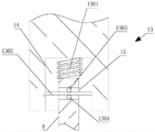
FIG. 5 is a schematic view of a buffering mechanism according to the present invention.
In the figure: 1 disc, 2 supports, 3 sockets, 4 blank openings, 5 first handles, 6 penetrating shafts, 7 test wire sockets, 8 support columns, 9 moving wheels, 10 second handles, 11 cleaning mechanisms, 1101 first gear, 1102 second gear, 1103U-shaped boxes, 1104 rotating shafts, 1105 rollers, 1106 mounting blocks, 1107 brushing plates, 1108 bristles, 1109 movable rods, 1110 cylindrical rods, 1111 return springs, 12 notches, 13 buffer mechanisms, 1301 buffer springs, 1302 elastic bodies, 1303 first rubber balls, 1304 second rubber balls, 14 grooves and 15 cylindrical through openings.
Detailed Description
The technical solutions in the embodiments of the present invention will be clearly and completely described below with reference to the drawings in the embodiments of the present invention, and it is obvious that the described embodiments are only a part of the embodiments of the present invention, and not all of the embodiments.
Examples of which are illustrated in the accompanying drawings, wherein like reference numerals refer to the same or similar elements or elements having the same or similar function throughout. The embodiments described below with reference to the drawings are illustrative and intended to be illustrative of the invention and are not to be construed as limiting the invention.
As shown in the figure, the 10kV grounding megger test wire containing device comprises a disc 1 and a support 2, wherein the outer surface of the support 2 is sequentially provided with a socket 3, an empty opening 4 and a test wire socket 7 from top to bottom, one side of the socket 3 is fixedly connected with one side of the support 2, one side of the empty opening 4 is fixedly connected with one side of the support 2, one side of the test wire socket 7 is fixedly connected with one side of the support 2, the disc 1 is arranged in the support 2, the disc 1 is fixedly sleeved on the outer wall of a penetrating shaft 6, the outer wall of the penetrating shaft 6 is rotatably connected with the support 2 through a bearing, one end of the penetrating shaft 6 is provided with a first handle 5, one side of the first handle 5 is fixedly connected with one end of the penetrating shaft 6, the outer edge of the first handle 5 is provided with a first anti-skid mark, the other end of the penetrating shaft 6 is provided with a second handle 10, one side of the second handle 10 is fixedly connected with the other end of the penetrating shaft 6, the outer edge of the second handle 10 is provided with a second anti-slip pattern, the first anti-slip pattern arranged on the outer edge of the first handle 5 can play a role in anti-slip, the phenomenon of hand slip when the first handle 5 is rotated is avoided, the second anti-slip pattern arranged on the outer edge of the second handle 10 can play a role in anti-slip, the phenomenon of hand slip when the second handle 10 is rotated is avoided, a cleaning mechanism 11 is arranged in the support 2, and a buffer mechanism 13 is arranged below the support 2;
the cleaning mechanism 11 comprises a first gear 1101, a second gear 1102, a U-shaped box 1103, a rotating shaft 1104, a roller 1105, a mounting block 1106, a brushing plate 1107, bristles 1108, a movable rod 1109, a cylindrical rod 1110 and a return spring 1111;
the inner wall of a first gear 1101 is fixedly connected with the outer wall of a through shaft 6, the outer edge of the first gear 1101 penetrates through the top of a U-shaped box 1103 and extends into the U-shaped box 1103, a second gear 1102 is arranged in the U-shaped box 1103, the U-shaped box 1103 is arranged below the through shaft 6, one side of the U-shaped box 1103 is fixedly connected with the inner surface of a support 2, the second gear 1102 is protected by the arranged U-shaped box 1103, the second gear 1102 is meshed with the first gear 1101, the through shaft 6 and a rotating shaft 1104 can be reversely rotated by the arranged first gear 1101 and the arranged second gear 1102, the cleaning effect can be better by the reverse rotation of the through shaft 6 and the rotating shaft 1104, one end of the rotating shaft 1104 is positioned in the U-shaped box 1103, the outer wall at one end of the rotating shaft 1104 is fixedly connected with the inner wall of the second gear 1102, the other end of the rotating shaft is rotatably connected with the inner surface of the support 2 by a second bearing, a roller 1104 is arranged behind the disc 1, the inner wall of a roller 1105 is fixedly connected with the outer wall of a rotating shaft 1104, one end of a mounting block 1106 is fixedly connected with the surface of the roller 1105, the top of the other end of the mounting block 1106 is provided with a notch 12, two ends of a cylindrical rod 1110 and one end of a movable rod 1109 fixedly connected with the inner wall of the notch 12 are movably sleeved on the outer wall of the cylindrical rod 1110, a brush plate 1107 is fixedly installed at the other end of the movable rod 1109, bristles 1108 are fixedly installed on the brush plate 1107, a return spring 1111 is sleeved on the outer wall of the cylindrical rod 1110, one end of the return spring 1111 is fixedly installed on the inner wall of the notch 12, the other end of the return spring 1111 is fixedly installed on the movable rod 1109, the movable rod 1109 can vibrate through the arranged return spring 1111, dust on the bristles 1108 can vibrate down through the vibration of the movable rod 1109, and the cleaning effect of the bristles 1108 is prevented from being influenced;
the buffer mechanism 13 includes a buffer spring 1301, an elastic body 1302, a first rubber ball 1303, and a second rubber ball 1304;
the lower part of the support 2 is provided with a moving wheel 9, the moving wheel 9 is fixedly arranged at the bottom of a support column 8, the moving wheel 9 can be conveniently moved by the device, so that the purpose of time saving and labor saving is achieved, the bottom of one end of the support 2 is provided with a groove 14, one side of the top end of the support column 8 is provided with a cylindrical through hole 15, a buffer spring 1301 is arranged in the groove 14, one end of the buffer spring 1301 is fixedly connected with the top of the inner wall of the groove 14, the other end of the buffer spring 1301 is fixedly connected with the top of the support column 8, one end of an elastic body 1302 is fixedly connected with the inner wall of the groove 14, the other end of the elastic body 1302 extends through the cylindrical through hole 15 to be fixedly connected with the inner wall of the groove 14, a first rubber ball 1303 and a second rubber ball 1304 are arranged in the cylindrical through hole 15, the top of the first rubber ball 1303 is fixedly connected with the bottom of the inner wall of the cylindrical through hole 15, the bottom of the first rubber ball 1303 is fixedly connected with the top of the elastic body 1302, the top of the second rubber ball 1304 is fixedly connected with the bottom of the elastic body 1302, and the bottom of the second rubber ball 1304 is fixedly connected with the bottom of the inner wall of the cylindrical through hole 15.
When the 10kV grounding megger test wire containing device is used, the penetrating shaft 6 can be rotated by rotating the first handle 5 or the second handle 10, finally, the test wire can be contained, the test wire is inevitably polluted in the containing process, the first gear 1101 can be rotated by rotating the penetrating shaft 6, the second gear 1102 can be rotated by rotating the first gear 1101, the rotating shaft 1104 can be rotated by rotating the second gear 1102, the roller 1105 can be rotated by rotating the rotating shaft 1104, the test wire can be cleaned by rotating the roller 1105 and rotating the bristles 1108, when the test wire is contained, a moving device is needed to move, the device can be conveniently moved by the arranged moving wheel 9, the moving wheel 9 can be conveniently moved, the moving wheel 9 can be damaged for a long time or a plurality of times, and the buffer effect can be generated by the arranged buffer spring 1301, the amplitude of the jolt is reduced, meanwhile, the elastic body 1302, the first rubber ball 1303 and the second rubber ball 1304 are arranged to produce a buffering effect, the amplitude of the jolt is reduced, and finally damage to the moving wheel 9 is reduced.
Although embodiments of the present invention have been shown and described above, it is understood that the above embodiments are exemplary and should not be construed as limiting the present invention, and that variations, modifications, substitutions and alterations can be made in the above embodiments by those of ordinary skill in the art without departing from the principle and spirit of the present invention. Any modification, equivalent replacement, or improvement made within the spirit and principle of the present invention should be included in the protection scope of the present invention.
Claims (4)
1.10kV ground connection megger test wire storage device, including disc (1), support (2), disc (1) sets up in support (2), its characterized in that: a cleaning mechanism (11) is arranged in the support (2), and a buffer mechanism (13) is arranged below the support (2);
the cleaning mechanism (11) comprises a first gear (1101), a second gear (1102), a U-shaped box (1103), a rotating shaft (1104), a roller (1105), a mounting block (1106), a brushing plate (1107), bristles (1108), a movable rod (1109), a cylindrical rod (1110) and a return spring (1111); the inner wall of the first gear (1101) is fixedly connected with the outer wall of the through shaft (6), the outer edge of the first gear (1101) penetrates through the top of the U-shaped box (1103) and extends into the U-shaped box (1103), the second gear (1102) is arranged in the U-shaped box (1103), the second gear (1102) is meshed with the first gear (1101), one end of the rotating shaft (1104) is located in the U-shaped box (1103), the outer wall of one end of the rotating shaft (1104) is fixedly connected with the inner wall of the second gear (1102), and the other end of the rotating shaft (1104) is rotatably connected with the inner surface of the bracket (2) through a second bearing; the roller (1105) is arranged at the rear of the disc (1), the inner wall of the roller (1105) is fixedly connected with the outer wall of the rotating shaft (1104), one end of the mounting block (1106) is fixedly connected with the surface of the roller (1105), the top of the other end of the mounting block (1106) is provided with a notch (12), two ends of the cylindrical rod (1110) are fixedly connected with the inner wall of the notch (12), one end of the movable rod (1109) is movably sleeved on the outer wall of the cylindrical rod (1110), the brush plate (1107) is fixedly arranged at the other end of the movable rod (1109), the brush hair (1108) is fixedly arranged on the brush plate (1107), the reset spring (1111) is sleeved on the outer wall of the cylindrical rod (1110), one end of the reset spring (1111) is fixedly arranged on the inner wall of the notch (12), and the other end of the reset spring (1111) is fixedly arranged on the movable rod (1109);
the buffer mechanism (13) comprises a buffer spring (1301), an elastic body (1302), a first rubber ball (1303) and a second rubber ball (1304), a moving wheel (9) is arranged below the support (2), the moving wheel (9) is fixedly installed at the bottom of the support column (8), a groove (14) is formed in the bottom of one end of the support (2), a cylindrical through hole (15) is formed in one side of the top end of the support column (8), the buffer spring (1301) is arranged in the groove (14), one end of the buffer spring (1301) is fixedly connected with the top of the inner wall of the groove (14), the other end of the buffer spring (1301) is fixedly connected with the top of the support column (8), one end of the elastic body (1302) is fixedly connected with the inner wall of the groove (14), and the other end of the elastic body (1302) extends to be fixedly connected with the inner wall of the groove (14) through the cylindrical through hole (15), first rubber ball (1303), second rubber ball (1304) set up in cylindricality opening (15), the top fixed connection of the top of first rubber ball (1303) and cylindricality opening (15) inner wall, the bottom of first rubber ball (1303) and the top fixed connection of elastomer (1302), the top of second rubber ball (1304) and the bottom fixed connection of elastomer (1302), the bottom of second rubber ball (1304) and the bottom fixed connection of cylindricality opening (15) inner wall.
2. The 10kV grounding megger test wire containing device of claim 1, wherein: the surface of support (2) is from last down having set gradually socket (3), empty (4), test wire socket (7) of opening, one side of socket (3) and one side fixed connection of support (2), one side of empty (4) and one side fixed connection of support (2) of opening, one side of test wire socket (7) and one side fixed connection of support (2).
3. The 10kV grounding megger test wire containing device of claim 1, wherein: the disc (1) is fixedly sleeved on the outer wall of the penetrating shaft (6), the outer wall of the penetrating shaft (6) is rotatably connected with the support (2) through a bearing, a first handle (5) is arranged at one end of the penetrating shaft (6), one side of the first handle (5) is fixedly connected with one end of the penetrating shaft (6), a first anti-slip pattern is formed in the outer edge of the first handle (5), a second handle (10) is arranged at the other end of the penetrating shaft (6), one side of the second handle (10) is fixedly connected with the other end of the penetrating shaft (6), and a second anti-slip pattern is formed in the outer edge of the second handle (10).
4. The 10kV grounding megger test wire containing device of claim 1, wherein: the U-shaped box (1103) is arranged below the penetrating shaft (6), and one side of the U-shaped box (1103) is fixedly connected with the inner surface of the support (2).
Priority Applications (1)
| Application Number | Priority Date | Filing Date | Title |
|---|---|---|---|
| CN202110609550.3A CN113419112B (en) | 2021-06-01 | 2021-06-01 | 10kV grounding megger test wire storage device |
Applications Claiming Priority (1)
| Application Number | Priority Date | Filing Date | Title |
|---|---|---|---|
| CN202110609550.3A CN113419112B (en) | 2021-06-01 | 2021-06-01 | 10kV grounding megger test wire storage device |
Publications (2)
| Publication Number | Publication Date |
|---|---|
| CN113419112A CN113419112A (en) | 2021-09-21 |
| CN113419112B true CN113419112B (en) | 2022-08-30 |
Family
ID=77713570
Family Applications (1)
| Application Number | Title | Priority Date | Filing Date |
|---|---|---|---|
| CN202110609550.3A Active CN113419112B (en) | 2021-06-01 | 2021-06-01 | 10kV grounding megger test wire storage device |
Country Status (1)
| Country | Link |
|---|---|
| CN (1) | CN113419112B (en) |
Citations (12)
| Publication number | Priority date | Publication date | Assignee | Title |
|---|---|---|---|---|
| FR527758A (en) * | 1916-03-23 | 1921-10-29 | Adhemar Detraux | Automatic reel for transporting an electric cable |
| WO1988006815A1 (en) * | 1987-03-04 | 1988-09-07 | Mitsubishi Denki Kabushiki Kaisha | Brush device |
| FR2668138A1 (en) * | 1990-10-19 | 1992-04-24 | Electricite De France | Apparatus for unreeling or rewinding one or more wires of great length and application to the measurement of earth-connection resistance |
| EP1245876A2 (en) * | 2001-03-30 | 2002-10-02 | Eagle Engineering Aerospace Co., Ltd. | Brush seal device |
| JP2005319351A (en) * | 2004-05-06 | 2005-11-17 | Honda Motor Co Ltd | Automatic mold cleaning device |
| CN103466394A (en) * | 2013-09-05 | 2013-12-25 | 国家电网公司 | Megger reeling and unreeling machine |
| CN203706838U (en) * | 2014-01-24 | 2014-07-09 | 广西电网公司电力科学研究院 | Electromagnetic coupling coil used for wireless power transmission |
| CN107253643A (en) * | 2017-07-04 | 2017-10-17 | 国网山东省电力公司梁山县供电公司 | A kind of drum of electrical test with automatic wire winding function |
| CN107994492A (en) * | 2017-12-24 | 2018-05-04 | 上力电力科技有限公司 | A kind of cleaning device inside high-tension switch cabinet |
| CN108516423A (en) * | 2018-05-13 | 2018-09-11 | 刘新娟 | A kind of draw off gear of power cable |
| CN109507484A (en) * | 2018-12-27 | 2019-03-22 | 国网青海省电力公司海西供电公司 | Ground resistance measuring instrument electricity box |
| CN109780133A (en) * | 2019-03-27 | 2019-05-21 | 天津鸿瑞特汽车配件有限公司 | A kind of vehicle shock pad that elastic property is good |
Family Cites Families (2)
| Publication number | Priority date | Publication date | Assignee | Title |
|---|---|---|---|---|
| CN108043757A (en) * | 2017-11-10 | 2018-05-18 | 湖南辉讯企业管理有限公司 | A kind of medical apparatus sterilizing cleaning device |
| CN108263918A (en) * | 2018-04-03 | 2018-07-10 | 李耀强 | Winch |
-
2021
- 2021-06-01 CN CN202110609550.3A patent/CN113419112B/en active Active
Patent Citations (12)
| Publication number | Priority date | Publication date | Assignee | Title |
|---|---|---|---|---|
| FR527758A (en) * | 1916-03-23 | 1921-10-29 | Adhemar Detraux | Automatic reel for transporting an electric cable |
| WO1988006815A1 (en) * | 1987-03-04 | 1988-09-07 | Mitsubishi Denki Kabushiki Kaisha | Brush device |
| FR2668138A1 (en) * | 1990-10-19 | 1992-04-24 | Electricite De France | Apparatus for unreeling or rewinding one or more wires of great length and application to the measurement of earth-connection resistance |
| EP1245876A2 (en) * | 2001-03-30 | 2002-10-02 | Eagle Engineering Aerospace Co., Ltd. | Brush seal device |
| JP2005319351A (en) * | 2004-05-06 | 2005-11-17 | Honda Motor Co Ltd | Automatic mold cleaning device |
| CN103466394A (en) * | 2013-09-05 | 2013-12-25 | 国家电网公司 | Megger reeling and unreeling machine |
| CN203706838U (en) * | 2014-01-24 | 2014-07-09 | 广西电网公司电力科学研究院 | Electromagnetic coupling coil used for wireless power transmission |
| CN107253643A (en) * | 2017-07-04 | 2017-10-17 | 国网山东省电力公司梁山县供电公司 | A kind of drum of electrical test with automatic wire winding function |
| CN107994492A (en) * | 2017-12-24 | 2018-05-04 | 上力电力科技有限公司 | A kind of cleaning device inside high-tension switch cabinet |
| CN108516423A (en) * | 2018-05-13 | 2018-09-11 | 刘新娟 | A kind of draw off gear of power cable |
| CN109507484A (en) * | 2018-12-27 | 2019-03-22 | 国网青海省电力公司海西供电公司 | Ground resistance measuring instrument electricity box |
| CN109780133A (en) * | 2019-03-27 | 2019-05-21 | 天津鸿瑞特汽车配件有限公司 | A kind of vehicle shock pad that elastic property is good |
Also Published As
| Publication number | Publication date |
|---|---|
| CN113419112A (en) | 2021-09-21 |
Similar Documents
| Publication | Publication Date | Title |
|---|---|---|
| CN210386834U (en) | Tunnel pipeline surface cleaning device | |
| CN113419112B (en) | 10kV grounding megger test wire storage device | |
| CN210649975U (en) | Grinding device with dustproof function | |
| CN211303948U (en) | Insulator cleaner | |
| CN210125956U (en) | Curved surface grinder is used in panel processing | |
| CN214513587U (en) | House building construction dust collector | |
| CN111362071B (en) | Cable coiling device | |
| KR200450965Y1 (en) | Marine Floor Cleaners | |
| CN103726467B (en) | Main brush of sweeper | |
| CN220800920U (en) | Roller brush module and cleaning equipment | |
| CN205917631U (en) | Square cleaning cart | |
| CN214259211U (en) | Carpet cleaning brush with height adjustment | |
| CN212313606U (en) | Travelling car convenient to mechanical equipment installation | |
| CN103481706A (en) | Blackboard eraser capable of removing accumulated dust | |
| CN214084326U (en) | Wheel changing cart | |
| CN221157797U (en) | Plastic film cleaning equipment with static-removing structure | |
| CN213429916U (en) | Indoor wall surface cleaning device | |
| CN223803338U (en) | A highly flexible omnidirectional wheel | |
| CN210936110U (en) | Arrester curing means | |
| CN119175962B (en) | A caster assembly for a high pressure cleaning machine | |
| US20240365965A1 (en) | Rotating drum push broom | |
| CN221645521U (en) | Marking line clearing device | |
| CN212265473U (en) | Instrument surface rust cleaning mechanism for machining | |
| CN212914935U (en) | Carbon fiber filter screen with S-shaped cross section for industrial air purifier | |
| CN221049752U (en) | Antiskid handcart tire |
Legal Events
| Date | Code | Title | Description |
|---|---|---|---|
| PB01 | Publication | ||
| PB01 | Publication | ||
| SE01 | Entry into force of request for substantive examination | ||
| SE01 | Entry into force of request for substantive examination | ||
| GR01 | Patent grant | ||
| GR01 | Patent grant |