CN113464458A - Condensate pump health state detection system and method - Google Patents
Condensate pump health state detection system and method Download PDFInfo
- Publication number
- CN113464458A CN113464458A CN202110811982.2A CN202110811982A CN113464458A CN 113464458 A CN113464458 A CN 113464458A CN 202110811982 A CN202110811982 A CN 202110811982A CN 113464458 A CN113464458 A CN 113464458A
- Authority
- CN
- China
- Prior art keywords
- bearing
- acceleration
- pump
- condensate pump
- end bearing
- Prior art date
- Legal status (The legal status is an assumption and is not a legal conclusion. Google has not performed a legal analysis and makes no representation as to the accuracy of the status listed.)
- Pending
Links
- 230000036541 health Effects 0.000 title claims abstract description 33
- 238000001514 detection method Methods 0.000 title claims abstract description 24
- 238000000034 method Methods 0.000 title claims description 25
- 230000001133 acceleration Effects 0.000 claims abstract description 146
- 238000012544 monitoring process Methods 0.000 claims abstract description 19
- 230000003862 health status Effects 0.000 claims description 3
- 230000005856 abnormality Effects 0.000 abstract description 3
- 230000002159 abnormal effect Effects 0.000 description 7
- 238000007726 management method Methods 0.000 description 4
- 238000010586 diagram Methods 0.000 description 3
- 230000005540 biological transmission Effects 0.000 description 2
- 238000004891 communication Methods 0.000 description 2
- 238000006073 displacement reaction Methods 0.000 description 2
- 238000011156 evaluation Methods 0.000 description 2
- 239000004519 grease Substances 0.000 description 2
- 238000007689 inspection Methods 0.000 description 2
- 238000009434 installation Methods 0.000 description 2
- 239000003973 paint Substances 0.000 description 2
- 230000003068 static effect Effects 0.000 description 2
- XLYOFNOQVPJJNP-UHFFFAOYSA-N water Substances O XLYOFNOQVPJJNP-UHFFFAOYSA-N 0.000 description 2
- 239000002390 adhesive tape Substances 0.000 description 1
- 230000003321 amplification Effects 0.000 description 1
- 238000010276 construction Methods 0.000 description 1
- 238000003745 diagnosis Methods 0.000 description 1
- 201000010099 disease Diseases 0.000 description 1
- 208000037265 diseases, disorders, signs and symptoms Diseases 0.000 description 1
- 230000000694 effects Effects 0.000 description 1
- 239000000835 fiber Substances 0.000 description 1
- 230000035784 germination Effects 0.000 description 1
- 238000012423 maintenance Methods 0.000 description 1
- 238000003199 nucleic acid amplification method Methods 0.000 description 1
- 230000002688 persistence Effects 0.000 description 1
- 238000010248 power generation Methods 0.000 description 1
- 230000008569 process Effects 0.000 description 1
- 230000000750 progressive effect Effects 0.000 description 1
- 230000004044 response Effects 0.000 description 1
- 238000005070 sampling Methods 0.000 description 1
- 230000009897 systematic effect Effects 0.000 description 1
- 238000012360 testing method Methods 0.000 description 1
Images




Classifications
-
- F—MECHANICAL ENGINEERING; LIGHTING; HEATING; WEAPONS; BLASTING
- F04—POSITIVE - DISPLACEMENT MACHINES FOR LIQUIDS; PUMPS FOR LIQUIDS OR ELASTIC FLUIDS
- F04D—NON-POSITIVE-DISPLACEMENT PUMPS
- F04D15/00—Control, e.g. regulation, of pumps, pumping installations or systems
- F04D15/0088—Testing machines
-
- F—MECHANICAL ENGINEERING; LIGHTING; HEATING; WEAPONS; BLASTING
- F04—POSITIVE - DISPLACEMENT MACHINES FOR LIQUIDS; PUMPS FOR LIQUIDS OR ELASTIC FLUIDS
- F04D—NON-POSITIVE-DISPLACEMENT PUMPS
- F04D13/00—Pumping installations or systems
- F04D13/02—Units comprising pumps and their driving means
- F04D13/06—Units comprising pumps and their driving means the pump being electrically driven
-
- F—MECHANICAL ENGINEERING; LIGHTING; HEATING; WEAPONS; BLASTING
- F04—POSITIVE - DISPLACEMENT MACHINES FOR LIQUIDS; PUMPS FOR LIQUIDS OR ELASTIC FLUIDS
- F04D—NON-POSITIVE-DISPLACEMENT PUMPS
- F04D15/00—Control, e.g. regulation, of pumps, pumping installations or systems
- F04D15/0077—Safety measures
-
- F—MECHANICAL ENGINEERING; LIGHTING; HEATING; WEAPONS; BLASTING
- F04—POSITIVE - DISPLACEMENT MACHINES FOR LIQUIDS; PUMPS FOR LIQUIDS OR ELASTIC FLUIDS
- F04D—NON-POSITIVE-DISPLACEMENT PUMPS
- F04D29/00—Details, component parts, or accessories
- F04D29/04—Shafts or bearings, or assemblies thereof
- F04D29/046—Bearings
Landscapes
- Engineering & Computer Science (AREA)
- Mechanical Engineering (AREA)
- General Engineering & Computer Science (AREA)
- Testing Of Devices, Machine Parts, Or Other Structures Thereof (AREA)
Abstract
The invention relates to a condensate pump health state detection system and a condensate pump health state detection method, wherein the system comprises a plurality of first acceleration sensors, a plurality of second acceleration sensors, a data acquisition unit and a background system, the plurality of first acceleration sensors are all arranged on a pump bearing of a condensate pump and used for measuring vibration data of the pump bearing, the plurality of second acceleration sensors are all arranged on a motor driving end bearing of the condensate pump and used for measuring vibration data of the motor driving end bearing, the background system determines the fault type of the condensate pump according to the vibration data of the pump bearing and the vibration data of the motor driving end bearing, real-time monitoring of the health state of the condensate pump is achieved, fault early warning is given out, timely and accurate feedback can be given when an abnormality occurs, and effective management and control are achieved for equipment management.
Description
Technical Field
The invention relates to the technical field of thermal power generation, in particular to a system and a method for detecting the health state of a condensate pump.
Background
The condensate pump (vertical barrel bag type) is mainly used for conveying condensate in a condenser in a thermal power thermodynamic system, and mainly comprises the following parts: the pump comprises a pump cylinder body, a working part, a water outlet part and a thrust device part. The main component influencing the health state of the condensate pump is a bearing, at present, the health state of the bearing of the condensate pump equipment is detected by adopting a traditional manual handheld equipment detection method, and the health state is estimated in a point inspection mode. However, the method for point inspection has limited sampling data, is difficult to form systematic assessment, and the assessment of the health state is performed by relying on the experience of personnel and matching with factory parameter information and data of equipment, so that irreparable loss is caused when problems are discovered.
Therefore, the prior art has no complete and accurate evaluation basis, cannot obtain timely and accurate feedback when an abnormality occurs, and cannot effectively manage and control equipment management. Therefore, there is a need for a method and system for detecting the health of a condensate pump in real time and providing early warning when the problem is still in the infancy stage.
Disclosure of Invention
The invention aims to provide a condensate pump health state detection system and method, which are used for monitoring the health state of a condensate pump in real time and giving out a fault type for early warning.
In order to achieve the purpose, the invention provides the following scheme:
a condensate pump health detection system, the system comprising: the system comprises a plurality of first acceleration sensors, a plurality of second acceleration sensors, a data acquisition unit and a background system;
the first acceleration sensors are all arranged on a pump bearing of the condensate pump; the plurality of second acceleration sensors are all arranged on a motor driving end bearing of the condensate pump;
the signal output ends of the first acceleration sensors are connected with the input end of the data acquisition unit, and the first acceleration sensors are used for measuring vibration data of the pump bearing;
the signal output ends of the second acceleration sensors are connected with the input end of the data acquisition unit, and the second acceleration sensors are used for measuring vibration data of the motor driving end bearing;
the output end of the data acquisition unit is connected with a background system, and the data acquisition unit is used for acquiring vibration data of the pump bearing and vibration data of the motor driving end bearing and transmitting the vibration data to the background system;
and the background system is used for determining the fault type of the condensate pump according to the vibration data of the pump bearing and the vibration data of the motor driving end bearing.
Optionally, the system further includes: a third acceleration sensor;
the third acceleration sensor is arranged on a motor non-driving end bearing of the condensate pump;
the signal output end of the third acceleration sensor is connected with the background system through the data acquisition unit; the third acceleration sensor is used for measuring the vertical acceleration of the motor non-drive-end bearing and transmitting the vertical acceleration of the motor non-drive-end bearing to the background system through the data acquisition unit;
the background system is used for displaying the vertical acceleration of the motor non-drive end bearing, comparing the vertical acceleration of the motor non-drive end bearing with the upper limit value and the lower limit value of a plurality of different acceleration threshold value ranges respectively, and outputting vibration state alarm signals of different levels;
the background system is also used for displaying the vibration data of the pump bearing and the vibration data of the motor driving end bearing, comparing the vibration data of the pump bearing and the vibration data of the motor driving end bearing with the upper limit value and the lower limit value of a plurality of different vibration threshold value ranges respectively, and outputting vibration state alarm signals of different levels.
Optionally, the system further includes: a plant-level monitoring information system of the thermal power plant;
the input end of the plant-level monitoring information system of the thermal power plant is connected with the condensate pump, and the output end of the plant-level monitoring information system of the thermal power plant is connected with the background system through the data acquisition unit; the thermal power plant-level monitoring information system is used for monitoring the operation data of the condensate pump and transmitting the operation data to the background system through the data acquisition unit; the operation data comprises motor temperature, motor revolution, inlet pressure value and outlet pressure value;
and the background system is used for displaying the operating data, comparing the operating data with the upper limit value and the lower limit value of a plurality of different operating data threshold value ranges, and outputting operating state alarm signals of different levels.
Optionally, the system further includes: the system comprises a regional switch, a data server and a network gate;
and the data acquisition unit transmits the vibration data of the pump bearing and the vibration data of the motor driving end bearing to a background system sequentially through the regional switch, the data server and the network gate.
Optionally, the background system includes:
the fault type determining unit is used for determining the fault type of the condensate pump according to the vibration data of the pump bearing and the vibration data of the motor driving end bearing; the vibration data comprises vertical direction acceleration, horizontal direction acceleration and vertical direction acceleration; the failure types include weak base and loose centering.
Optionally, the fault type determining unit includes:
a weak foundation fault type determination subunit, configured to determine that the fault type of the condensate pump is weak foundation if a difference between a vertical direction acceleration of the pump bearing and a vertical direction acceleration of the motor drive end bearing is greater than a vertical vibration threshold, or a difference between a horizontal direction acceleration of the pump bearing and a horizontal direction acceleration of the motor drive end bearing is greater than a horizontal vibration threshold;
the circle center position determining subunit is used for determining the circle center position of a circle formed by rotation of the pump bearing according to the vertical direction acceleration, the horizontal direction acceleration and the vertical direction acceleration of the pump bearing, and determining the circle center position of the circle formed by rotation of the motor driving end bearing according to the vertical direction acceleration, the horizontal direction acceleration and the vertical direction acceleration of the motor driving end bearing;
and the misalignment fault type determining subunit is used for determining that the fault type of the condensate pump is misalignment if the circle center position of the circle formed by the rotation of the pump bearing is different from the circle center position of the circle formed by the rotation of the motor driving end bearing.
Optionally, the carrier of the background system is a computer and/or a handheld device.
A condensate pump state of health detection method, the method comprising:
acquiring vibration data of a pump bearing in a condensate pump and vibration data of a motor driving end bearing in the condensate pump; the vibration data comprises vertical direction acceleration, horizontal direction acceleration and vertical direction acceleration;
determining the fault type of the condensate pump according to the vibration data of the pump bearing and the vibration data of the motor driving end bearing; the failure types include weak base and loose centering.
Optionally, determining a fault type of the condensate pump according to the vibration data of the pump bearing and the vibration data of the motor driving end bearing specifically includes:
if the difference value between the acceleration of the pump bearing in the vertical direction and the acceleration of the motor driving end bearing in the vertical direction is larger than a vertical vibration threshold value, or the difference value between the acceleration of the pump bearing in the horizontal direction and the acceleration of the motor driving end bearing in the horizontal direction is larger than a horizontal vibration threshold value, determining that the fault type of the condensate pump is not firm;
determining the circle center position of a circle formed by the rotation of the pump bearing according to the vertical direction acceleration, the horizontal direction acceleration and the vertical direction acceleration of the pump bearing, and determining the circle center position of the circle formed by the rotation of the motor driving end bearing according to the vertical direction acceleration, the horizontal direction acceleration and the vertical direction acceleration of the motor driving end bearing;
and if the circle center position of the circumference formed by the rotation of the pump bearing is different from the circle center position of the circumference formed by the rotation of the motor driving end bearing, determining the fault type of the condensate pump as misalignment.
According to the specific embodiment provided by the invention, the invention discloses the following technical effects:
the invention provides a condensate pump health state detection system and a condensate pump health state detection method, wherein a plurality of first acceleration sensors are arranged on a pump bearing of a condensate pump and used for measuring vibration data of the pump bearing, a plurality of second acceleration sensors are arranged on a motor driving end bearing of the condensate pump and used for measuring vibration data of the motor driving end bearing, and a background system determines the fault type of the condensate pump according to the vibration data of the pump bearing and the vibration data of the motor driving end bearing, so that the real-time monitoring of the health state of the condensate pump is realized, the fault type is given for fault early warning, and the system can feed back timely and accurately when an abnormality occurs, so that the equipment management is effectively controlled.
Drawings
In order to more clearly illustrate the embodiments of the present invention or the technical solutions in the prior art, the drawings needed to be used in the embodiments will be briefly described below, and it is obvious that the drawings in the following description are only some embodiments of the present invention, and it is obvious for those skilled in the art to obtain other drawings without inventive exercise.
FIG. 1 is a network architecture diagram of a condensate pump health status detection system according to the present invention;
FIG. 2 is a schematic diagram of a condensate pump health detection system in accordance with the present invention;
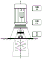
FIG. 3 is a schematic view of the installation position of an acceleration sensor of a condensate pump of the basic structure provided by the present invention;
FIG. 4 is a schematic view of an installation position of an acceleration sensor when the condensate pump is an open-type pump according to the present invention;
FIG. 5 is a schematic view of an acceleration sensor installed when the condensate pump is a closed pump according to the present invention;
FIG. 6 is a system architecture diagram of a backend system provided by the present invention;
fig. 7 is a flowchart of a method for detecting a health state of a condensate pump according to the present invention.
Detailed Description
The technical solutions in the embodiments of the present invention will be clearly and completely described below with reference to the drawings in the embodiments of the present invention, and it is obvious that the described embodiments are only a part of the embodiments of the present invention, and not all of the embodiments. All other embodiments, which can be derived by a person skilled in the art from the embodiments given herein without making any creative effort, shall fall within the protection scope of the present invention.
The invention aims to provide a condensate pump health state detection system and method, which are used for monitoring the health state of a condensate pump in real time and giving out a fault type for early warning.
In order to make the aforementioned objects, features and advantages of the present invention comprehensible, embodiments accompanied with figures are described in further detail below.
The invention mainly implements and manages the condensate pump in the auxiliary machine in the field of thermal power plants, and the condensate pump mainly comprises the following parts: the pump cylinder body, the working part, the water outlet part and the thrust device part are necessary to carry out scientific health state evaluation on the main parts.
To this end, the present invention provides a condensate pump health status detection system, as shown in fig. 1-2, comprising: the system comprises a plurality of first acceleration sensors, a plurality of second acceleration sensors, a data acquisition unit and a background system;
the first acceleration sensors are all arranged on a pump bearing of the condensate pump; the plurality of second acceleration sensors are all arranged on a motor driving end bearing of the condensate pump;
the signal output ends of the first acceleration sensors are connected with the input end of the data acquisition unit, and the first acceleration sensors are used for measuring vibration data of the pump bearing;
the signal output ends of the second acceleration sensors are connected with the input end of the data acquisition unit, and the second acceleration sensors are used for measuring vibration data of a bearing at the driving end of the motor;
the output end of the data acquisition unit is connected with the background system, and the data acquisition unit is used for acquiring vibration data of the pump bearing and vibration data of the motor drive end bearing and transmitting the vibration data to the background system;
and the background system is used for determining the fault type of the condensate pump according to the vibration data of the pump bearing and the vibration data of the motor driving end bearing.
The acceleration sensor mounting positions are schematically shown in fig. 3 to 5, and circles in the drawings indicate the acceleration sensor mounting positions.
The acceleration sensor mounting method mainly comprises two methods: firstly, adhering and mounting; and installing screws.
Adhering and mounting:
a smooth, flat surface is selected for mounting. The surface of the equipment is treated, paint, grease and the like are removed, the surface of the equipment is ensured to be smooth, and the surface of the equipment is ensured to be fully contacted with the surface of the base. If the base needs to be bonded on the cambered surface, grinding is firstly carried out.
The base bond should be cured for more than 24 hours. In order to ensure the firm bonding of the base, the base is prevented from being stressed within 24 hours. (can be fixed by transparent adhesive tape to avoid dropping and ensure the setting time.)
Installing screws:
a smooth, flat surface is selected for mounting. The surface of the equipment is treated, paint, grease and the like are removed, the surface of the equipment is ensured to be smooth, and the surface of the equipment is ensured to be fully contacted with the surface of the base. If the base needs to be bonded on the cambered surface, grinding is firstly carried out.
The system further comprises: a third acceleration sensor; the third acceleration sensor is arranged on a motor non-driving end bearing of the condensate pump;
the signal output end of the third acceleration sensor is connected with the background system through the data acquisition unit; the third acceleration sensor is used for measuring the vertical acceleration of the motor non-drive end bearing and transmitting the vertical acceleration of the motor non-drive end bearing to the background system through the data acquisition unit;
the background system is used for displaying the vertical acceleration of the motor non-drive end bearing, comparing the vertical acceleration of the motor non-drive end bearing with the upper limit value and the lower limit value of a plurality of different acceleration threshold ranges respectively, and outputting vibration state alarm signals of different levels;
the background system is also used for displaying the vibration data of the pump bearing and the vibration data of the motor driving end bearing, comparing the vibration data of the pump bearing and the vibration data of the motor driving end bearing with the upper limit value and the lower limit value of a plurality of different vibration threshold value ranges respectively, and outputting vibration state alarm signals of different levels.
The summary is that the condensate pump mainly vibrates the measuring point:
vertical vibration of pump bearings
Horizontal vibration of pump bearing
Axial vibration of pump bearing
Vertical vibration of the motor drive end bearing
Horizontal vibration of the motor drive end bearing
Axial vibration of the motor drive end bearing
Horizontal vibration of the non-drive-end bearing of the motor
Preferably, the vibration data includes vertical direction acceleration, horizontal direction acceleration and vertical direction acceleration, and the plurality of different acceleration threshold ranges are the same as the plurality of different vibration threshold ranges, as shown in table 1.
TABLE 1 vibration level
| Vibration value | Grade | Color(s) |
| 0-2.0 | Is low in | Light green |
| 2.0-4.5 | Is normal | Green colour |
| 4.6-5.0 | Light and slight | Blue color |
| 5.1-7.0 | Severe severity of disease | Yellow colour |
| 7.0 or more | Is very serious | Purple color |
For example, the delivery value of the vertical vibration of a free end bearing of a motor of the condensate pump is 4.5mm/s, and when the value transmitted back by a sensor is detected to be more than 4.5mm/s, the super-vibration alarm is directly prompted.
The system further comprises: a plant-level monitoring information system of the thermal power plant; the input end of the plant-level monitoring information system of the thermal power plant is connected with the condensate pump, and the output end of the plant-level monitoring information system of the thermal power plant is connected with the background system through the data acquisition unit; the thermal power plant-level monitoring information system is used for monitoring the operation data of the condensate pump and transmitting the operation data to the background system through the data acquisition unit; the operation data comprises motor temperature, motor revolution, inlet pressure value and outlet pressure value; the background system is used for displaying the operation data, comparing the operation data with the upper limit value and the lower limit value of a plurality of different operation data threshold value ranges, and outputting operation state alarm signals of different levels.
As shown in fig. 1, the system further comprises: the system comprises a regional switch, a data server and a network gate; the data acquisition unit transmits the vibration data of the pump bearing and the vibration data of the motor drive end bearing to the background system sequentially through the regional switch, the data server and the network gate. The carrier of the background system is a computer and/or a handheld device.
The network is added between the first area (sensitive area) and the third area (application area is open), so that the data can only be transmitted by a one-way channel, and the first area flows to the third area; and the three areas can not flow to the first area, so that data transmission is realized and data safety is guaranteed.
The background system comprises:
the fault type determining unit is used for determining the fault type of the condensate pump according to the vibration data of the pump bearing and the vibration data of the motor driving end bearing; the vibration data comprises vertical direction acceleration, horizontal direction acceleration and vertical direction acceleration; the failure types include weak base and misalignment.
The fault type determination unit includes:
the fault type determining subunit is used for determining that the fault type of the condensate pump is not firm on the basis if the difference value between the acceleration in the vertical direction of the pump bearing and the acceleration in the vertical direction of the motor driving end bearing is greater than a vertical vibration threshold value or the difference value between the acceleration in the horizontal direction of the pump bearing and the acceleration in the horizontal direction of the motor driving end bearing is greater than a horizontal vibration threshold value;
the circle center position determining subunit is used for determining the circle center position of a circle formed by the rotation of the pump bearing according to the vertical direction acceleration, the horizontal direction acceleration and the vertical direction acceleration of the pump bearing, and determining the circle center position of the circle formed by the rotation of the motor driving end bearing according to the vertical direction acceleration, the horizontal direction acceleration and the vertical direction acceleration of the motor driving end bearing;
and the misalignment fault type determining subunit is used for determining that the fault type of the condensate pump is misalignment if the circle center position of the circle formed by the rotation of the pump bearing is different from the circle center position of the circle formed by the rotation of the motor drive end bearing.
The background system determines the fault type of the condensate pump by utilizing an expert knowledge base, and specifically comprises the following steps:
bearing anomalies are all searchable according to a certain rule, particularly on bearings; the abnormal occurrence of the bearing can be divided into the following stages: the slight indirectness of the vibration amplitude becomes high, and becomes high after a certain period of time of the persistence, then the sound abnormity occurs, and finally the temperature of the whole bearing rises.
Summarizing various regular searchable technical communication conclusions in the same industry to form a huge scientific data intelligence library system; and inputting the related indexes into the intelligent base to carry out intelligent calculation of big data and obtain corresponding problem feedback. The correspondence between the vibration source and the fault type is shown in table 2:
TABLE 2 correspondence between vibration source and fault type

The corresponding principle of the vibration source and the fault type is as follows:
the bearing seat dynamic stiffness detection method adopts positive reasoning to diagnose vibration faults, and one of the two faults of exciting force and support dynamic stiffness should be determined or eliminated firstly. A large number of field practices prove that the detection of the dynamic stiffness of the bearing seat is a simple and effective method, and further observation shows that the dynamic stiffness of the bearing seat is directly related to the connection stiffness of the bearing seat under the dynamic condition besides the static stiffness and the resonance amplification factor, and the detection and diagnosis method of the factor influencing the dynamic stiffness is specifically described below.
The support system for connecting the rigid rotor is generally formed by combining a bearing cover, a bearing seat, a base bedplate, a base beam and other components, and the connection tightness of the components directly influences the rigidity of the components. The influence of the tightness of the connection between the parts on the rigidity is called the connection rigidity.
The traditional method for checking the connection tightness of the components comprises the methods of checking the pretightening force of a connecting screw, the clearance between connecting components and the like.
The method is obtained by summarizing a large number of field vibration test results, and the method is a simple and effective method for detecting the connection tightness of the connecting parts under the dynamic condition by detecting the differential vibration among the connecting parts.
The differential vibration is a difference in amplitude between two adjacent connecting members. The differential vibration value itself indicates that relative displacement is generated between two adjacent connecting parts under dynamic conditions, the slight displacement can obviously reduce the dynamic rigidity of the parts, but no gap exists between the connecting parts under static conditions, and the pretightening force of the connecting screw is normal.
For a general bearing seat, in the same axial position, the difference between the upper and lower standard heights of a measuring point is within 100mm, and under the condition of tight connection and surrounding fixation, the differential vibration of the two connecting parts is less than 2 μm; the normal differential vibration between the sliding surfaces should be less than 5 μm; for the motor with the insulating pad between the rear bearing seat and the bedplate, the differential vibration should be less than 7 μm. When the difference vibration of two adjacent parts is obviously larger than the values, the insufficient connection rigidity of the bearing seat can be judged.
The vibration source can be obtained from the insufficient rigidity, and the larger the vibration is, the more serious the fault is, can be directly judged according to the value. The connecting rigidity is insufficient, the main reason is the bearing seat which is a foundation relative to the condensate pump; therefore, the vibration source type with abnormal foundation is divided into weak foundation.
After the expert knowledge base is established, a management system is established, and the information acquired by the expert knowledge base is visualized.
The architecture of the background system built by the invention is shown in fig. 6. NET MVC architecture is adopted, a database adopts MongoDB and Sql Server for storage, Output Caching, Data Caching and Fiber Distributed Data Interface (FDDI) are used for Caching, and transmission between a Data layer and an application layer is realized through Web Server service.
The system collects and integrates the data, the process data, the equipment parameters and the expert knowledge base obtained by the sensor, and establishes management on the system; the data is enabled to have a centralized display platform, and the data is displayed on a background page in a list form.
The invention installs acceleration transducer additionally at the key bearing part, collects the state data in real time as the technical data support point, and cooperates with the knowledge base (equipment abnormal state expression) at home and abroad to access the system background, and displays the abnormal occurrence point and the severity of the abnormal occurrence; and when the important parts are abnormal and the important parts are in the early germination stage, the automatic alarm response is carried out, and an abnormal maintenance suggestion is given.
The invention can quickly establish various communications, and has the advantages of low cost, quick implementation and short construction period.
Corresponding to a system for detecting the health state of the condensate pump, the invention also provides a method for detecting the health state of the condensate pump, as shown in fig. 7, the method comprises the following steps:
acquiring vibration data of a pump bearing in a condensate pump and vibration data of a motor driving end bearing in the condensate pump; the vibration data comprises vertical direction acceleration, horizontal direction acceleration and vertical direction acceleration;
determining the fault type of the condensate pump according to the vibration data of the pump bearing and the vibration data of the motor driving end bearing; the fault types comprise weak foundation and loose centering, and specifically comprise:
if the difference value between the acceleration of the pump bearing in the vertical direction and the acceleration of the motor driving end bearing in the vertical direction is larger than the vertical vibration threshold value, or the difference value between the acceleration of the pump bearing in the horizontal direction and the acceleration of the motor driving end bearing in the horizontal direction is larger than the horizontal vibration threshold value, determining the fault type of the condensate pump as a basis;
determining the circle center position of a circle formed by the rotation of the pump bearing according to the vertical direction acceleration, the horizontal direction acceleration and the vertical direction acceleration of the pump bearing, and determining the circle center position of the circle formed by the rotation of the motor driving end bearing according to the vertical direction acceleration, the horizontal direction acceleration and the vertical direction acceleration of the motor driving end bearing;
and if the circle center position of the circumference formed by the rotation of the pump bearing is different from the circle center position of the circumference formed by the rotation of the motor driving end bearing, determining the fault type of the condensate pump as misalignment.
The embodiments in the present description are described in a progressive manner, each embodiment focuses on differences from other embodiments, and the same and similar parts among the embodiments are referred to each other.
The principles and embodiments of the present invention have been described herein using specific examples, which are provided only to help understand the method and the core concept of the present invention; meanwhile, for a person skilled in the art, according to the idea of the present invention, the specific embodiments and the application range may be changed. In view of the above, the present disclosure should not be construed as limiting the invention.
Claims (9)
1. A condensate pump health detection system, the system comprising: the system comprises a plurality of first acceleration sensors, a plurality of second acceleration sensors, a data acquisition unit and a background system;
the first acceleration sensors are all arranged on a pump bearing of the condensate pump; the plurality of second acceleration sensors are all arranged on a motor driving end bearing of the condensate pump;
the signal output ends of the first acceleration sensors are connected with the input end of the data acquisition unit, and the first acceleration sensors are used for measuring vibration data of the pump bearing;
the signal output ends of the second acceleration sensors are connected with the input end of the data acquisition unit, and the second acceleration sensors are used for measuring vibration data of the motor driving end bearing;
the output end of the data acquisition unit is connected with a background system, and the data acquisition unit is used for acquiring vibration data of the pump bearing and vibration data of the motor driving end bearing and transmitting the vibration data to the background system;
and the background system is used for determining the fault type of the condensate pump according to the vibration data of the pump bearing and the vibration data of the motor driving end bearing.
2. The condensate pump state of health detection system of claim 1, further comprising: a third acceleration sensor;
the third acceleration sensor is arranged on a motor non-driving end bearing of the condensate pump;
the signal output end of the third acceleration sensor is connected with the background system through the data acquisition unit; the third acceleration sensor is used for measuring the vertical acceleration of the motor non-drive-end bearing and transmitting the vertical acceleration of the motor non-drive-end bearing to the background system through the data acquisition unit;
the background system is used for displaying the vertical acceleration of the motor non-drive end bearing, comparing the vertical acceleration of the motor non-drive end bearing with the upper limit value and the lower limit value of a plurality of different acceleration threshold value ranges respectively, and outputting vibration state alarm signals of different levels;
the background system is also used for displaying the vibration data of the pump bearing and the vibration data of the motor driving end bearing, comparing the vibration data of the pump bearing and the vibration data of the motor driving end bearing with the upper limit value and the lower limit value of a plurality of different vibration threshold value ranges respectively, and outputting vibration state alarm signals of different levels.
3. The condensate pump state of health detection system of claim 1, further comprising: a plant-level monitoring information system of the thermal power plant;
the input end of the plant-level monitoring information system of the thermal power plant is connected with the condensate pump, and the output end of the plant-level monitoring information system of the thermal power plant is connected with the background system through the data acquisition unit; the thermal power plant-level monitoring information system is used for monitoring the operation data of the condensate pump and transmitting the operation data to the background system through the data acquisition unit; the operation data comprises motor temperature, motor revolution, inlet pressure value and outlet pressure value;
and the background system is used for displaying the operating data, comparing the operating data with the upper limit value and the lower limit value of a plurality of different operating data threshold value ranges, and outputting operating state alarm signals of different levels.
4. The condensate pump state of health detection system of claim 1, further comprising: the system comprises a regional switch, a data server and a network gate;
and the data acquisition unit transmits the vibration data of the pump bearing and the vibration data of the motor driving end bearing to a background system sequentially through the regional switch, the data server and the network gate.
5. The condensate pump state of health detection system of claim 1, wherein the back-office system comprises:
the fault type determining unit is used for determining the fault type of the condensate pump according to the vibration data of the pump bearing and the vibration data of the motor driving end bearing; the vibration data comprises vertical direction acceleration, horizontal direction acceleration and vertical direction acceleration; the failure types include weak base and loose centering.
6. The condensate pump state of health detection system of claim 5, wherein the fault type determination unit comprises:
a weak foundation fault type determination subunit, configured to determine that the fault type of the condensate pump is weak foundation if a difference between a vertical direction acceleration of the pump bearing and a vertical direction acceleration of the motor drive end bearing is greater than a vertical vibration threshold, or a difference between a horizontal direction acceleration of the pump bearing and a horizontal direction acceleration of the motor drive end bearing is greater than a horizontal vibration threshold;
the circle center position determining subunit is used for determining the circle center position of a circle formed by rotation of the pump bearing according to the vertical direction acceleration, the horizontal direction acceleration and the vertical direction acceleration of the pump bearing, and determining the circle center position of the circle formed by rotation of the motor driving end bearing according to the vertical direction acceleration, the horizontal direction acceleration and the vertical direction acceleration of the motor driving end bearing;
and the misalignment fault type determining subunit is used for determining that the fault type of the condensate pump is misalignment if the circle center position of the circle formed by the rotation of the pump bearing is different from the circle center position of the circle formed by the rotation of the motor driving end bearing.
7. The condensate pump state of health detection system of claim 1, wherein the carrier of the back-office system is a computer and/or a handheld device.
8. A method of detecting a state of health of a condensate pump, the method comprising:
acquiring vibration data of a pump bearing in a condensate pump and vibration data of a motor driving end bearing in the condensate pump; the vibration data comprises vertical direction acceleration, horizontal direction acceleration and vertical direction acceleration;
determining the fault type of the condensate pump according to the vibration data of the pump bearing and the vibration data of the motor driving end bearing; the failure types include weak base and loose centering.
9. The method for detecting the health status of the condensate pump according to claim 8, wherein determining the fault type of the condensate pump according to the vibration data of the pump bearing and the vibration data of the motor driving end bearing specifically comprises:
if the difference value between the acceleration of the pump bearing in the vertical direction and the acceleration of the motor driving end bearing in the vertical direction is larger than a vertical vibration threshold value, or the difference value between the acceleration of the pump bearing in the horizontal direction and the acceleration of the motor driving end bearing in the horizontal direction is larger than a horizontal vibration threshold value, determining that the fault type of the condensate pump is not firm;
determining the circle center position of a circle formed by the rotation of the pump bearing according to the vertical direction acceleration, the horizontal direction acceleration and the vertical direction acceleration of the pump bearing, and determining the circle center position of the circle formed by the rotation of the motor driving end bearing according to the vertical direction acceleration, the horizontal direction acceleration and the vertical direction acceleration of the motor driving end bearing;
and if the circle center position of the circumference formed by the rotation of the pump bearing is different from the circle center position of the circumference formed by the rotation of the motor driving end bearing, determining the fault type of the condensate pump as misalignment.
Priority Applications (1)
| Application Number | Priority Date | Filing Date | Title |
|---|---|---|---|
| CN202110811982.2A CN113464458A (en) | 2021-07-19 | 2021-07-19 | Condensate pump health state detection system and method |
Applications Claiming Priority (1)
| Application Number | Priority Date | Filing Date | Title |
|---|---|---|---|
| CN202110811982.2A CN113464458A (en) | 2021-07-19 | 2021-07-19 | Condensate pump health state detection system and method |
Publications (1)
| Publication Number | Publication Date |
|---|---|
| CN113464458A true CN113464458A (en) | 2021-10-01 |
Family
ID=77881048
Family Applications (1)
| Application Number | Title | Priority Date | Filing Date |
|---|---|---|---|
| CN202110811982.2A Pending CN113464458A (en) | 2021-07-19 | 2021-07-19 | Condensate pump health state detection system and method |
Country Status (1)
| Country | Link |
|---|---|
| CN (1) | CN113464458A (en) |
Cited By (2)
| Publication number | Priority date | Publication date | Assignee | Title |
|---|---|---|---|---|
| CN114294249A (en) * | 2021-12-25 | 2022-04-08 | 上海水泵制造有限公司 | Detection apparatus for condensate pump |
| WO2024084451A1 (en) * | 2022-10-21 | 2024-04-25 | Forbes Marshall Technology Pvt. Ltd | A system for failure detection in a condensate pump |
Citations (4)
| Publication number | Priority date | Publication date | Assignee | Title |
|---|---|---|---|---|
| CN103498790A (en) * | 2013-10-18 | 2014-01-08 | 中国石油化工股份有限公司 | Pump group state monitoring method and device based on fiber grating sensing |
| CN104392020A (en) * | 2014-10-22 | 2015-03-04 | 北京必可测科技股份有限公司 | Display method and device for vibration fault of rotating machine |
| US10168248B1 (en) * | 2015-03-27 | 2019-01-01 | Tensor Systems Pty Ltd | Vibration measurement and analysis |
| CN212744387U (en) * | 2020-08-18 | 2021-03-19 | 华能济南黄台发电有限公司 | Vertical condensate pump state monitoring device |
-
2021
- 2021-07-19 CN CN202110811982.2A patent/CN113464458A/en active Pending
Patent Citations (4)
| Publication number | Priority date | Publication date | Assignee | Title |
|---|---|---|---|---|
| CN103498790A (en) * | 2013-10-18 | 2014-01-08 | 中国石油化工股份有限公司 | Pump group state monitoring method and device based on fiber grating sensing |
| CN104392020A (en) * | 2014-10-22 | 2015-03-04 | 北京必可测科技股份有限公司 | Display method and device for vibration fault of rotating machine |
| US10168248B1 (en) * | 2015-03-27 | 2019-01-01 | Tensor Systems Pty Ltd | Vibration measurement and analysis |
| CN212744387U (en) * | 2020-08-18 | 2021-03-19 | 华能济南黄台发电有限公司 | Vertical condensate pump state monitoring device |
Non-Patent Citations (2)
| Title |
|---|
| 赵顺萍等: "应用振动监测与故障分析诊断技术提高泵站设备管理水平", 《中国给水排水》 * |
| 邵慧飚: "汽轮发电机组振动故障浅析", 《科技情报开发与经济》 * |
Cited By (3)
| Publication number | Priority date | Publication date | Assignee | Title |
|---|---|---|---|---|
| CN114294249A (en) * | 2021-12-25 | 2022-04-08 | 上海水泵制造有限公司 | Detection apparatus for condensate pump |
| CN114294249B (en) * | 2021-12-25 | 2023-11-28 | 上海水泵制造有限公司 | Condensate pump's detection device |
| WO2024084451A1 (en) * | 2022-10-21 | 2024-04-25 | Forbes Marshall Technology Pvt. Ltd | A system for failure detection in a condensate pump |
Similar Documents
| Publication | Publication Date | Title |
|---|---|---|
| KR102344852B1 (en) | Digital Twin-based Prediction and Diagnostic Device for Pump Bearing Systems | |
| CN107168201B (en) | A real-time monitoring equipment operation and maintenance management system for engine test bench | |
| CN112213131B (en) | Rotary machine overhauls and fault diagnosis analog system | |
| US6853951B2 (en) | Methods and systems for analyzing the degradation and failure of mechanical systems | |
| GB2583402A (en) | Method and system for data driven machine diagnostics | |
| CN103116537A (en) | Condition monitoring system and method | |
| CN101776508A (en) | Optical-mechanical-electrical multi-parameter accurate monitoring device of rotating machine | |
| KR101843365B1 (en) | Integrated Diagnostic System and Database based on rules and cases | |
| CN206132392U (en) | Fan trouble experimental simulation platform | |
| US12602036B2 (en) | System for predictive operational analysis of a machinery component | |
| CN113464458A (en) | Condensate pump health state detection system and method | |
| CN113464711A (en) | Valve internal leakage monitoring system and method based on vibration measurement technology | |
| CN113418731A (en) | Online fault diagnosis method for cigarette making machine set | |
| CN113280910A (en) | Real-time monitoring method and system for long product production line equipment | |
| CN104808655A (en) | Online diagnosis device and method for large-scale rotating machinery equipment peaking-shaft system | |
| CN110160896A (en) | A kind of cooling cycle water pipe deflects durable test device and test method | |
| CN117589444B (en) | A wind turbine gearbox fault diagnosis method based on federated learning | |
| CN104819860A (en) | Petrochemical large-machine-set fault diagnosis simulation test machine unit device | |
| JPH05157668A (en) | Method and device for detecting abnormality of plant equipment | |
| CN118275502A (en) | Nuclear power plant rotating equipment bearing grease lubrication test device | |
| CN108896781A (en) | A kind of portable commercial vehicle odd-side jackshaft revolving speed rapid survey mechanism and method | |
| CN115752852A (en) | Online monitoring system and method for stress load of support and hanger | |
| CN109426211A (en) | Combined trouble-shooter and method towards petrochemical industry large-sized unit | |
| RU118378U1 (en) | HYDRAULIC DIAGNOSTIC DEVICE | |
| CN113959716B (en) | Method, device, storage medium and machine equipment for bearing condition monitoring |
Legal Events
| Date | Code | Title | Description |
|---|---|---|---|
| PB01 | Publication | ||
| PB01 | Publication | ||
| SE01 | Entry into force of request for substantive examination | ||
| SE01 | Entry into force of request for substantive examination | ||
| RJ01 | Rejection of invention patent application after publication |
Application publication date: 20211001 |
|
| RJ01 | Rejection of invention patent application after publication |