Detailed Description
In order to facilitate understanding of the embodiments of the present invention, the following technical points are described below:
(1) main scenarios of DC/CA:
according to different wireless access technologies and core network types, the DC scenarios can be classified into the following:
when the Core network is an Evolved Packet Core (EPC):
an EN-DC (EUTRA-NR Dual Connection), a multi-system Dual Connection (MR-DC) architecture with an Evolved Node B (eNB) as an MN and an EN-gNB (a 5 th generation mobile communication technology (5G) base station, referred to as EN-gNB, interfacing with a fourth generation mobile communication technology (4G) core network under an Option3 series non-independent networking architecture as an SN);
when the Core network is a 5G Core network (5G Core, 5 GC):
a new air interface dual connection (NR-DC), an MR-DC architecture with gNB as MN and gNB as SN;
a Multi-rate Dual Connectivity (MR-DC) architecture in which a 5G NR is connected to a 4G radio access network, and a gbb is MN, and a Next Generation base station (NG-eNB) is SN;
a 4G wireless access network under a 5G core network and a 5G NR dual-connection (NGEN-DC) MR-DC framework with NG-eNB as MN and gNB as SN;
(2) dual connectivity uplink power sharing mechanism:
in NR-DC, the UE maximum uplink transmission power (P) is assumedtotal) Certainly, when the MCG uplink transmission in the master cell group and the SCG uplink transmission in the secondary cell group occur simultaneously (i.e. overlap, specifically, the uplink transmission of any serving cell in the MCG and the uplink transmission of any serving cell in the SCG occur simultaneously), the UE needs to adjust the uplink transmission power of the MCG or the SCG to ensure that the sum of the MCG and the SCG does not exceed Ptotal。
Suppose that the UE starts SCG uplink transmission at time T0, and SCG uplink transmission power is denoted pwr _ SCG. The UE calculates pwr _ SCG at time T0 according to the following:
before time T0-T _ offset, the UE monitors the Physical Downlink Control Channel (PDCCH) of the MCG:
■ if the PDCCH triggers/indicates the UE to have an overlapped MCG uplink transmission with the SCG uplink transmission at the time of T0, the SCG uplink transmission power of the UE should beThe satisfaction of pwr _ SCG<=min{PSCG,Ptotal-MCG tx power }; wherein P istotalIs the maximum uplink transmission power, P, of the UESCGThe maximum uplink transmission power of the SCG is MCG tx power;
■ otherwise, pwr _ SCG<=Ptotal;
After T0-T _ offset, the UE does not want the PDCCH of the MCG to schedule the UE to perform MCG uplink transmission in overlap with the SCG uplink transmission at time T0.
Wherein, T _ offset is a time offset used by the UE in the uplink power sharing mechanism, and the value of T _ offset is described as follows:
the value of the currently specified T _ offset is
Wherein
For the maximum preparation time of the UE in the MCG,
the maximum preparation time for the UE in the SCG. In "Look-ahead",
is taken as T
proc,2,T
proc,CSI,
And/or
Maximum value of (1); in "not using look-ahead" (see-ahead),
is taken as T
proc,2,T
proc,CSI,
And/or
Maximum value of (2).
Explanation of the above parameters:
■Tproc,2processing time for the terminal in a Physical Uplink Shared Channel (PUSCH) of the MCG or the SCG;
the processing time may be understood as preparation time, processing time, preparation delay, processing delay, or the like.
■Tproc,CSIPreparing time for Channel State Information (CSI) of the terminal in the MCG or SCG;
■
preparing time for the terminal to send SPS PDSCH release on MCG or SCG when PUSCH or PUCCH is multiplexed with other PUCCH and/or PUSCH;
■
preparing time for a PUSCH of a terminal when the PUSCH of MCG or SCG is multiplexed with a PUCCH and/or other PUSCHs;
■
and preparing time for the terminal to send CSI on the MCG or SCG, or CSI preparation time when the PUSCH or PUCCH which is used for sending CSI is multiplexed with other PUCCHs or PUSCHs.
In the process of implementing the invention, the following problems exist in the prior art:
1) the UE can calculate the above parameters according to the received MCG configuration, SCG configuration and part of protocol agreed parameter values
And
thereby acquiring T _ offset. Since at [ T0-T _ offset, T0]During this period, there is a risk that the MN schedules the UE (the UE may not listen to the uplink scheduling of the MN during this period). It will be appreciated that at [ T0-T _ offset, T0]Meanwhile, if the MCG chooses not to schedule the UE, there is a certain loss, and the larger the value of T _ offset, the greater the loss suffered by the MCG for uplink transmission.
When the SN configures SCG configuration for the UE, there are two ways to transmit to the UE:
mode 1: transmitted to the UE via MN SRB 1;
mode 2: SN transmitted to the UE via SRB 3.
In the method 1, the MN may obtain the SCG configuration information in the same UE acquisition method when transmitting the SCG configuration information
And
and T _ offset.
In mode 2, the MN cannot acquire the SCG configuration, and thus cannot calculate
And
and T _ offset.
2) Since the UE monitors the PDCCH of the MCG to determine whether there is transmission of overlap before time T0-T _ offset, if so, it needs to preferentially ensure the uplink transmission power of the MCG and adjust the uplink transmission power of the SCG.
The technical solutions in the embodiments of the present invention will be clearly and completely described below with reference to the drawings in the embodiments of the present invention, and it is obvious that the described embodiments are some, not all, embodiments of the present invention. All other embodiments, which can be derived by a person skilled in the art from the embodiments given herein without making any creative effort, shall fall within the protection scope of the present invention.
The terms "comprises," "comprising," or any other variation thereof, in the description and claims of this application, are intended to cover a non-exclusive inclusion, such that a process, method, system, article, or apparatus that comprises a list of steps or elements is not necessarily limited to those steps or elements expressly listed, but may include other steps or elements not expressly listed or inherent to such process, method, article, or apparatus. Furthermore, the use of "and/or" in the specification and claims means that at least one of the connected objects, such as a and/or B, means that three cases, a alone, B alone, and both a and B, exist.
In the embodiments of the present invention, words such as "exemplary" or "for example" are used to mean serving as examples, illustrations or descriptions. Any embodiment or design described as "exemplary" or "e.g.," an embodiment of the present invention is not necessarily to be construed as preferred or advantageous over other embodiments or designs. Rather, use of the word "exemplary" or "such as" is intended to present concepts related in a concrete fashion.
The techniques described herein are not limited to Long Time Evolution (LTE)/LTE Evolution (LTE-Advanced) systems, and may also be used for various wireless communication systems, such as Code Division Multiple Access (CDMA), Time Division Multiple Access (TDMA), Frequency Division Multiple Access (FDMA), Orthogonal Frequency Division Multiple Access (OFDMA), Single-carrier Frequency-Division Multiple Access (SC-FDMA), and other systems.
The terms "system" and "network" are often used interchangeably. CDMA systems may implement Radio technologies such as CDMA2000, Universal Terrestrial Radio Access (UTRA), and so on. UTRA includes Wideband CDMA (Wideband Code Division Multiple Access, WCDMA) and other CDMA variants. TDMA systems may implement radio technologies such as Global System for Mobile communications (GSM). The OFDMA system may implement radio technologies such as Ultra Mobile Broadband (UMB), evolved-UTRA (E-UTRA), IEEE 802.11(Wi-Fi), IEEE 802.16(WiMAX), IEEE 802.20, Flash-OFDM, etc. UTRA and E-UTRA are parts of the Universal Mobile Telecommunications System (UMTS). LTE and higher LTE (e.g., LTE-A) are new UMTS releases that use E-UTRA. UTRA, E-UTRA, UMTS, LTE-A, and GSM are described in documents from an organization named "third Generation Partnership Project" (3 GPP). CDMA2000 and UMB are described in documents from an organization named "third generation partnership project 2" (3GPP 2). The techniques described herein may be used for both the above-mentioned systems and radio technologies, as well as for other systems and radio technologies.
Embodiments of the present invention are described below with reference to the accompanying drawings. The method and the equipment for transmission control provided by the embodiment of the invention can be applied to a wireless communication system. Referring to fig. 1, an architecture diagram of a wireless communication system according to an embodiment of the present invention is shown. As shown in fig. 1, the wireless communication system may include: network device 10, network device 11, and terminal 12, terminal 12 may be referred to as UE12, and terminal 12 may communicate (transmit signaling or transmit data) with network device 10 and network device 11. In practical applications, the connections between the above devices may be wireless connections, and fig. 1 illustrates the connections between the devices by solid lines for convenience and convenience in visual representation.
The network device 10 and the network device 11 provided in the embodiment of the present invention may be base stations, which may be commonly used base stations, evolved node base stations (enbs), or network devices in a 5G system (for example, next generation base stations (gnbs) or Transmission and Reception Points (TRPs)).
The terminal 12 provided in the embodiment of the present invention may be a Mobile phone, a tablet Computer, a notebook Computer, an Ultra-Mobile Personal Computer (UMPC), a netbook or a Personal Digital Assistant (PDA), a Mobile Internet Device (MID), a Wearable Device (Wearable Device), or a vehicle-mounted Device.
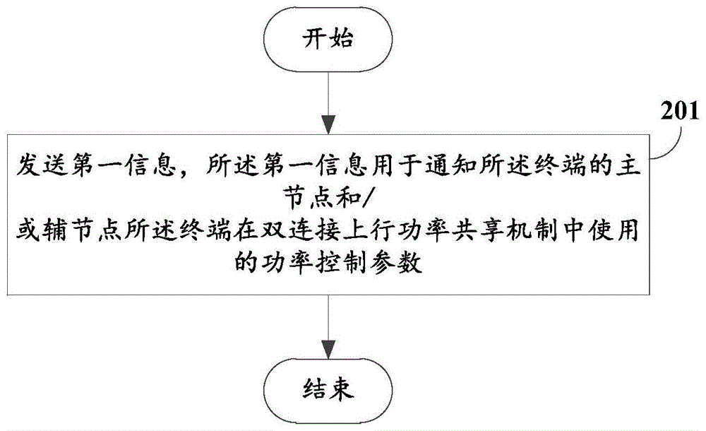
Referring to fig. 2, an embodiment of the present invention further provides a method for transmission control, where an execution main body of the method is a terminal, and the method includes: step 201.
Step 201: sending first information, where the first information is used to notify a Master Node (MN) and/or a Secondary Node (SN) of the terminal of a power control parameter used by the terminal in a dual-connection uplink power sharing mechanism, so that the Master Node and/or the Secondary Node perform transmission control according to the first information, for example, perform power control on uplink transmission in an MCG or an SCG, optimize network scheduling, and the like.
In some implementations, the terminal directly sends at least part of the content of the first information to the primary node or the secondary node, where the first information is used to inform a primary node of the terminal of a power control parameter used by the terminal in a dual-connection uplink power sharing mechanism; or the terminal sends at least part of content of the first information to the secondary node through the primary node, wherein the first information is used for informing the secondary node of the terminal of a power control parameter used by the terminal in a dual-connection uplink power sharing mechanism; or the terminal sends at least part of the content of the first information to the main node through the auxiliary node, wherein the first information is used for informing the main node of the terminal of the power control parameter used by the terminal in the dual-connection uplink power sharing mechanism.
In some implementations, the terminal transmits the first information by one of: (a) terminal auxiliary information; (b) a Radio Resource Control (RRC) reconfiguration complete message; (c) a terminal capability; (d) an RRC connection recovery complete message; and (e) an RRC connection setup complete message. That is, the terminal may report the first information to the network device in one of (a) to (e) carried by the terminal.
In some embodiments, the first information may include at least one of:
(1) a time offset (T _ offset) used by the uplink power sharing mechanism;
for example, the MN may obtain the T _ offset through the first information, and the MN may optimize network scheduling according to the T _ offset, so as to avoid loss of uplink transmission of the MCG.
For another example, the SN may obtain the T _ offset through the first information, and the SN may schedule the UE to perform SCG uplink transmission at a suitable time, so as to avoid the uplink transmission of the SCG from being lost.
(2) Maximum preparation time of the terminal in SCG;
for example, the MN may calculate T _ offset according to the maximum preparation time of the terminal in the SCG, so as to optimize network scheduling, for example, schedule the UE for MCG uplink transmission at a proper time, and avoid the MCG uplink transmission from being lost.
(3) Maximum preparation time of the terminal at MCG;
for example, the SN may calculate T _ offset according to the maximum preparation time of the MCG by the terminal, and the SN may know whether the UE can use the maximum uplink total power to perform SCG uplink transmission, so as to optimize network scheduling, for example, schedule the UE to perform SCG uplink transmission at a proper time, and avoid the uplink transmission of SCG from being lost.
Alternatively, the MN may transmit the terminal to the SN at the maximum preparation time of the MCG, or the terminal may transmit the terminal to the SN at the maximum preparation time of the MCG.
(4) A first set of parameters for calculating a maximum preparation time of the MCG;
for example, the SN may calculate T _ offset according to the maximum preparation time of the MCG by the terminal, and the SN may know whether the UE can use the maximum uplink total power to perform SCG uplink transmission, so as to optimize network scheduling, for example, schedule the UE to perform SCG uplink transmission at a proper time, and avoid the uplink transmission of SCG from being lost.
(5) A second set of parameters for calculating a maximum preparation time for the SCG.
For example, the MN may calculate T _ offset according to the maximum preparation time of the terminal in the SCG, so as to optimize network scheduling, for example, schedule the UE for MCG uplink transmission at a proper time, and avoid the MCG uplink transmission from being lost. It is to be understood that transmitting at least part of the first information corresponds to transmitting one or more of (1) to (5) of the power control parameters, or transmitting at least part of the first parameter set or the second parameter set.
Optionally, the first set of parameters comprises at least one of:
(1) the terminal prepares time in PUSCH of the MCG;
it can be understood that the PUSCH preparation time, i.e., the time from the terminal receiving the last symbol of the PDCCH scheduling the PUSCH to the UE starting to transmit the PUSCH.
(2) The CSI preparation time of the terminal at the MCG;
(3) the PUSCH preparation time of the terminal when the PUSCH of the MCG is multiplexed with the PUCCH and/or other PUSCHs;
it is understood that other PUSCHs may refer to PUSCHs other than the PUSCH of the MCG.
(4) The terminal sends CSI preparation time when the PUSCH or PUCCH of CSI is multiplexed with other PUCCH or PUSCH on the MCG;
it is understood that other PUCCH or PUSCH refers to a PUCCH or PUSCH other than the PUCCH or PUSCH on which CSI is transmitted on the MCG.
(5) The terminal sends SPS PDSCH release preparation time when the PUSCH or PUCCH of SPS PDSCH release is multiplexed with other PUCCHs and/or PUSCHs on the MCG;
it is understood that other PUCCH or PUSCH refers to a PUCCH or PUSCH other than the PUCCH or PUSCH on which SPS PDSCH release is transmitted on the MCG.
(6) A third parameter for the terminal to calculate one or more of:
a PUSCH preparation time of the MCG or a CSI preparation time of the MCG;
and PUSCH preparation time, CSI preparation time or SPS PDSCH release preparation time when the PUCCH or PUSCH of the MCG is multiplexed with other PUCCH and/or PUSCH.
It is understood that other PUCCH or PUSCH refers to PUCCH or PUSCH other than PUCCH or PUSCH of MCG.
It is to be understood that the third parameter may not be limited to one, and may be a plurality.
Optionally, the second set of parameters comprises at least one of:
(1) the terminal prepares time in PUSCH of the SCG;
(2) the terminal is in the CSI preparation time of the SCG;
(3) a PUSCH preparation time of the terminal when the PUSCH of the SCG is multiplexed with the PUCCH and/or other PUSCHs;
(4) the terminal sends CSI preparation time when the PUSCH or PUCCH of CSI is multiplexed with other PUCCHs or PUSCHs on the SCG;
(5) the terminal sends SPS PDSCH release preparation time when the PUSCH or PUCCH of SPS PDSCH release is multiplexed with other PUCCHs and/or PUSCHs on the SCG;
(6) a fourth parameter for the terminal to calculate one or more of:
a PUSCH preparation time or a CSI preparation time at the SCG;
and PUSCH preparation time, CSI preparation time or SPS PDSCH release preparation time when the PUCCH or PUSCH of the SCG is multiplexed with other PUCCH and/or PUSCH.
It is to be understood that the fourth parameter may not be limited to one, and may be a plurality.
In the embodiment of the invention, the terminal reports the power control parameters used in the dual-connection uplink power sharing mechanism to the network side, so that the main node and/or the auxiliary node of the terminal can perform transmission control according to the power distribution condition of the terminal, for example, perform power control on uplink transmission in MCG or SCG, optimize network scheduling and the like, and improve the uplink transmission quality.
Referring to fig. 3, an embodiment of the present invention further provides a transmission control method, where an execution main body of the method is a network device, and the method includes: step 301 and step 302.
Step 301: receiving first information from a terminal, wherein the first information is used for informing a main node and/or an auxiliary node of the terminal of a power control parameter used by the terminal in a dual-connection uplink power sharing mechanism.
For example, the network device is a secondary node of the terminal, and the secondary node may receive at least part of the content in the first information from the terminal through the primary node.
In some embodiments, the first information may include at least one of:
(1) a time offset used by the uplink power sharing mechanism;
for example, the MN may obtain the T _ offset through the first information, and the MN may optimize network scheduling according to the T _ offset, so as to avoid loss of uplink transmission of the MCG. For another example, the SN may obtain the T _ offset through the first information, and the SN may schedule the UE to perform SCG uplink transmission at a suitable time, so as to avoid the uplink transmission of the SCG from being lost.
(2) Maximum preparation time of the terminal in SCG;
for example, the MN may calculate T _ offset according to the maximum preparation time of the terminal in the SCG, so as to optimize network scheduling, for example, schedule the UE for MCG uplink transmission at a proper time, and avoid the MCG uplink transmission from being lost.
(3) Maximum preparation time of the terminal at MCG;
for example, the SN may calculate T _ offset according to the maximum preparation time of the MCG by the terminal, and the SN may know whether the UE can use the maximum uplink total power to perform SCG uplink transmission, so as to optimize network scheduling, for example, schedule the UE to perform SCG uplink transmission at a proper time, and avoid the uplink transmission of SCG from being lost.
(4) A first set of parameters for calculating a maximum preparation time of the MCG;
for example, the SN may calculate T _ offset according to the maximum preparation time of the MCG by the terminal, and the SN may know whether the UE can use the maximum uplink total power to perform SCG uplink transmission, so as to optimize network scheduling, for example, schedule the UE to perform SCG uplink transmission at a proper time, and avoid the uplink transmission of SCG from being lost.
(5) A second set of parameters for calculating a maximum preparation time for the SCG.
For example, the MN may calculate T _ offset according to the maximum preparation time of the terminal in the SCG, so as to optimize network scheduling, for example, schedule the UE for MCG uplink transmission at a proper time, and avoid the MCG uplink transmission from being lost.
It should be noted that the description of the first parameter set and the second parameter set may refer to the embodiment shown in fig. 2.
Step 302: and performing transmission control on the terminal according to the first information.
Optionally, the performing transmission control on the terminal includes at least one of:
(1) controlling the uplink transmission power of the terminal in the master cell group;
for example, the uplink transmission power of the terminal in any serving cell in the master cell group is controlled;
(2) controlling the uplink transmission power of the terminal in the auxiliary cell group;
for example, the uplink transmission power of any one serving cell in the terminal secondary cell group is controlled.
(3) Optimizing network scheduling;
for example, adjusting the uplink transmission position of the terminal in the master cell group; or, the terminal is scheduled to perform uplink transmission at a proper time; or controlling the terminal to perform uplink transmission preferentially or later, and the like.
Optionally, the network device is a master node of the terminal, and the method further includes: sending second information to an auxiliary node of the terminal, wherein the second information comprises at least one of the following items:
(1) a time offset used by the uplink power sharing mechanism;
(2) maximum preparation time of the terminal at MCG;
(3) the terminal prepares time in PUSCH of the MCG;
(4) the CSI preparation time of the terminal at the MCG;
(5) the PUSCH preparation time of the terminal when the PUSCH of the MCG is multiplexed with the PUCCH and/or other PUSCHs;
(6) the terminal sends CSI or CSI preparation time when the PUSCH of the CSI is multiplexed with other PUCCHs and/or PUSCHs on the MCG;
(7) the terminal sends SPS PDSCH release preparation time when the PUSCH or PUCCH of SPS PDSCH release is multiplexed with other PUCCHs and/or PUSCHs on the MCG;
(8) a fifth parameter for the terminal to calculate one or more of:
a PUSCH preparation time or a CSI preparation time of the MCG;
PUSCH preparation time, CSI preparation time or SPS PDSCH release preparation time when the PUCCH or PUSCH of the MCG is multiplexed with other PUCCH and/or PUSCH;
it is to be understood that the fifth parameter may not be limited to one, and may be a plurality.
(9) And a sixth parameter, where the sixth parameter is used for the secondary node to acquire relevant configuration information of the terminal in a physical downlink control channel of the MCG.
It is to be understood that the sixth parameter may not be limited to one, and may be a plurality.
It can be understood that, the secondary node obtains the PDCCH configuration of the terminal in the MCG, and can presume whether the UE can use the maximum uplink total power to perform SCG uplink transmission, and then the secondary node optimizes network scheduling or controls transmission power according to the information.
Optionally, the network device is an auxiliary node of the terminal, and the method further includes: sending third information to a master node of the terminal, wherein the third information comprises at least one of the following information:
(1) a time offset used by the terminal in the uplink power sharing mechanism;
(2) maximum preparation time of the terminal in SCG;
(3) the terminal prepares time in PUSCH of the SCG;
(4) the terminal is in the CSI preparation time of the SCG;
(5) a PUSCH preparation time of the terminal when the PUSCH of the SCG is multiplexed with the PUCCH and/or other PUCCHs and/or PUSCHs;
(6) the terminal sends CSI preparation time when the PUSCH or PUCCH of CSI is multiplexed with other PUCCHs or PUSCHs on the SCG;
(7) the terminal sends SPS PDSCH release preparation time when the PUSCH or PUCCH of SPS PDSCH release is multiplexed with other PUCCHs and/or PUSCHs on the SCG;
(8) a seventh parameter for the terminal to calculate one or more of:
a PUSCH preparation time or a CSI preparation time of the SCG;
a PUSCH preparation time, a CSI preparation time or an SPS PDSCH release preparation time when the PUCCH or PUSCH of the SCG is multiplexed with other PUCCH and/or PUSCH;
it is to be understood that the seventh parameter may not be limited to one, and may be a plurality.
(9) And an eighth parameter, where the eighth parameter is used for the secondary node to acquire configuration information of the terminal in a physical downlink control channel of the SCG.
It is to be understood that the eighth parameter may not be limited to one, and may be a plurality.
In the embodiment of the present invention, the master node and/or the slave node of the terminal may perform transmission control according to the power allocation reported by the terminal, for example, perform power control on uplink transmission in the MCG or SCG, optimize network scheduling, and improve the uplink transmission quality in the MCG or SCG.
The following description is given with reference to the first embodiment, the second embodiment, the third embodiment, and the fourth embodiment.
The first embodiment is as follows:
step 1: the MN sends MCG configuration to UE on an MCG Signaling Radio Bearers (SRB) 1;
step 2: after receiving MCG configuration, UE calculates T according to configuration parameters in MCG configuration and parameter values agreed by part of protocols
proc,2、T
proc,CSI、
And takeWherein the maximum value is
And step 3: the SN sends the SCG configuration to the UE through the SRB 3;
and 4, step 4: after the UE receives the SCG configuration, the T is calculated according to the configuration parameters in the SCG configuration and the parameter values agreed by part of protocols
proc,2、T
proc,CSI、
Taking the maximum value as
And 5: the UE will
And
set the maximum value of T _ offset;
step 6: the UE sends information A to the MN, wherein the information A comprises T _ offset;
and 7: and the MN performs network scheduling according to the T _ offset.
And 8: optionally, the UE sends information B to the SN, where the information B includes T _ offset;
for example, the information B may be transmitted through MCG SRB1 or SRB 3.
And step 9: and the SN performs network scheduling according to the T _ offset.
It is understood that the above-described information a and information B correspond to the first information.
Example two
Step 1: the MN sends MCG configuration to the UE at MCG SRB 1;
step 2: after receiving MCG configuration, UE calculates T according to configuration parameters in MCG configuration and parameter values agreed by part of protocols
proc,2、T
proc,CSI、
Taking the maximum value as
And step 3: the SN sends the SCG configuration to the UE through the SRB 3;
and 4, step 4: after the UE receives the SCG configuration, the T is calculated according to the configuration parameters in the SCG configuration and the parameter values agreed by part of protocols
proc,2、T
proc,CSI、
Taking the maximum value as
And 5: the UE will
And
set the maximum value of T _ offset;
step 6: the UE will send information a to the MN, the information a containing at least one of:
t corresponding to SCG
proc,2、T
proc,CSI、
And 7: the MN carries out network scheduling according to the information A;
and 8: the UE will send information B to the SN, which contains at least one of:
t corresponding to MCG
proc,2、T
proc,CSI、
And step 9: and the SN schedules the network according to the information B.
It is understood that the above-described information a and information B correspond to the first information.
Example three:
step 1: UE sends information A to MN;
optionally, the information a includes at least one of the following:
t corresponding to MCG
proc,2、T
proc,CSI、
T corresponding to SCG
proc,2、T
proc,CSI、
Step 2: MN sends information B to SN;
optionally, the information B contains at least one of: t _ offset,
T corresponding to MCG
proc,2、T
proc,CSI、
PDCCH configuration information of the MCG;
optionally, the PDCCH configuration information includes one of:
(1) serving cell PDCCH configuration information in serving cell configuration (UE-specific);
(2) PDCCH public configuration information in the public configuration of the downlink bandwidth part;
(3) PDCCH configuration information in downlink bandwidth portion allocations;
and step 3: the SN obtains the MCG PDCCH configuration in the information B, and knows that the UE receives an MCG uplink transmission on the PDCCH of the MCG before T0-T _ offset, and the transmission overlaps with the SCG uplink transmission at time T0, and according to the dual connectivity power sharing mechanism, the uplink transmission power of the UE on the SCG is reduced.
If the MCG has no uplink transmission for a longer period of time after T0-T _ offset, the SN may reschedule the UE for a longer period of time for transmission of the maximum uplink power later, while avoiding low power transmission at time T0.
It is understood that the above-described information a and information B correspond to the first information.
Example four
Step 1: the MN sends MCG configuration to the UE at MCG SRB 1;
step 2: after receiving MCG configuration, UE calculates T according to configuration parameters in MCG configuration and parameter values agreed by part of protocols
proc,2、T
proc,CSI、
Taking the maximum value as
And step 3: the SN sends the SCG configuration to the UE through the SRB 3;
and 4, step 4: after the UE receives the SCG configuration, the T is calculated according to the configuration parameters and the parameter values agreed by part of protocols
proc,2、T
proc,CSI、
Taking the maximum value as
And 5: the UE will
And
set the maximum value of T _ offset;
step 6: the UE sends information A to the MN, wherein the information A comprises at least one of the following items: calculating T corresponding to SCG
proc,2、T
proc,CSI、
The necessary parameters, such as subcarrier spacing, parameters, etc.;
and 7: the MN carries out network scheduling according to the information B;
and 8: the UE will send information B to the SN, which contains at least one of: calculating T corresponding to MCG
proc,2、T
proc,CSI、
The necessary parameters, such as subcarrier spacing, parameters, etc.;
and step 9: and the SN schedules the network according to the information B.
It is understood that the above-described information a and information B correspond to the first information.
Referring to fig. 4, an embodiment of the present invention further provides a terminal, where the terminal 400 includes:
a first sending module 401, configured to send first information, where the first information is used to notify a primary node and/or a secondary node of the terminal of a power control parameter used by the terminal in a dual-connection uplink power sharing mechanism, so that the primary node and/or the secondary node perform power control according to the first information.
In some implementations, the first sending module 401 may send the first information directly to the master node; or, the first sending module 401 sends the first information to the secondary node through the primary node.
In some implementations, the terminal sends the first information via one of the following messages: (a) terminal auxiliary information; (b) RRC reconfiguration complete message; (c) a terminal capability; (d) an RRC connection recovery complete message; and (e) an RRC connection setup complete message.
In some embodiments, the first information may include at least one of:
(1) a time offset used by the uplink power sharing mechanism;
(2) maximum preparation time of the terminal at MCG;
(3) maximum preparation time of the terminal in SCG;
(4) a first set of parameters for calculating a maximum preparation time of the MCG;
(5) a second set of parameters for calculating a maximum preparation time for the SCG.
Optionally, the first set of parameters comprises at least one of:
(1) the terminal prepares time in PUSCH of the MCG;
it can be understood that the PUSCH preparation time, i.e., the time from the terminal receiving the last symbol of the PDCCH scheduling the PUSCH to the UE starting to transmit the PUSCH.
(2) The CSI preparation time of the terminal at the MCG;
(3) the PUSCH preparation time of the terminal when the PUSCH of the MCG is multiplexed with the PUCCH and/or other PUSCHs;
(4) the terminal sends CSI preparation time when the PUSCH or PUCCH of CSI is multiplexed with other PUCCH or PUSCH on the MCG;
(5) the terminal sends SPS PDSCH release preparation time when the PUSCH or PUCCH of SPS PDSCH release is multiplexed with other PUCCHs and/or PUSCHs on the MCG;
(6) a third parameter for the terminal to calculate one or more of:
a PUSCH preparation time of the MCG or a CSI preparation time of the MCG;
and PUSCH preparation time, CSI preparation time or SPS PDSCH release preparation time when the PUCCH or PUSCH of the MCG is multiplexed with other PUCCH and/or PUSCH.
It is to be understood that the third parameter may not be limited to one, and may be a plurality.
Optionally, the second set of parameters comprises at least one of:
(1) the terminal prepares time in PUSCH of the SCG;
(2) the terminal is in the CSI preparation time of the SCG;
(3) a PUSCH preparation time of the terminal when the PUSCH of the SCG is multiplexed with the PUCCH and/or other PUSCHs;
(4) the terminal sends CSI preparation time when the PUSCH or PUCCH of CSI is multiplexed with other PUCCHs or PUSCHs on the SCG;
(5) the terminal sends SPS PDSCH release preparation time when the PUSCH or PUCCH of SPS PDSCH release is multiplexed with other PUCCHs and/or PUSCHs on the SCG;
(6) a fourth parameter for the terminal to calculate one or more of:
a PUSCH preparation time or a CSI preparation time at the SCG;
and PUSCH preparation time, CSI preparation time or SPS PDSCH release preparation time when the PUCCH or PUSCH of the SCG is multiplexed with other PUCCH and/or PUSCH.
It is to be understood that the fourth parameter may not be limited to one, and may be a plurality.
The terminal provided in the embodiment of the present invention may execute the method embodiment shown in fig. 2, which has similar implementation principles and technical effects, and this embodiment is not described herein again.
Referring to fig. 5, an embodiment of the present invention further provides a network device, where the network device 500 includes:
a receiving module 501, configured to receive first information from a terminal, where the first information is used to notify a primary node and/or a secondary node of the terminal of a power control parameter used by the terminal in a dual-connection uplink power sharing mechanism;
for example, the network device is a secondary node of a terminal, and the receiving module 501 may receive at least part of the content in the first information from the terminal through the primary node.
A control module 502, configured to perform transmission control on the terminal according to the first information.
Optionally, the performing transmission control on the terminal includes at least one of:
(1) controlling the uplink transmission power of the terminal in the master cell group;
for example, the uplink transmission power of the terminal in any serving cell in the master cell group is controlled;
(2) controlling the uplink transmission power of the terminal in the auxiliary cell group;
for example, the uplink transmission power of any one serving cell in the terminal secondary cell group is controlled.
(3) Optimizing network scheduling;
for example, adjusting the uplink transmission position of the terminal in the master cell group; or, the terminal is scheduled to perform uplink transmission at a proper time; or controlling the terminal to perform uplink transmission preferentially or later, and the like.
Optionally, the network device 500 is a master node of the terminal, and the network device 500 further includes:
a second sending module, configured to send second information to an auxiliary node of the terminal, where the second information includes at least one of the following:
(1) a time offset used by the uplink power sharing mechanism;
(2) maximum preparation time of the terminal at MCG;
(3) the terminal prepares time in PUSCH of the MCG;
(4) the CSI preparation time of the terminal at the MCG;
(5) the PUSCH preparation time of the terminal when the PUSCH of the MCG is multiplexed with the PUCCH and/or other PUSCHs;
(6) the terminal sends CSI or CSI preparation time when the PUSCH of the CSI is multiplexed with other PUCCHs and/or PUSCHs on the MCG;
(7) the terminal sends SPS PDSCH release preparation time when the PUSCH or PUCCH of SPS PDSCH release is multiplexed with other PUCCHs and/or PUSCHs on the MCG;
(8) a fifth parameter for the terminal to calculate one or more of:
a PUSCH preparation time or a CSI preparation time of the MCG;
PUSCH preparation time, CSI preparation time or SPS PDSCH release preparation time when the PUCCH or PUSCH of the MCG is multiplexed with other PUCCH and/or PUSCH;
it is to be understood that the fifth parameter may not be limited to one, and may be a plurality.
(9) And a sixth parameter, where the sixth parameter is used for the secondary node to acquire configuration information of the terminal in a physical downlink control channel of the MCG.
It is to be understood that the sixth parameter may not be limited to one, and may be a plurality.
Optionally, the network device 500 is an auxiliary node of the terminal, and the network device 500 further includes:
a third sending module, configured to send third information to a master node of the terminal, where the third information includes at least one of the following information:
(1) a time offset used by the terminal in the uplink power sharing mechanism;
(2) maximum preparation time of the terminal in SCG;
(3) the terminal prepares time in PUSCH of the SCG;
(4) the terminal is in the CSI preparation time of the SCG;
(5) a PUSCH preparation time of the terminal when the PUSCH of the SCG is multiplexed with the PUCCH and/or other PUCCHs and/or PUSCHs;
(6) the terminal sends CSI preparation time when the PUSCH or PUCCH of CSI is multiplexed with other PUCCHs or PUSCHs on the SCG;
(7) the terminal sends SPS PDSCH release preparation time when the PUSCH or PUCCH of SPS PDSCH release is multiplexed with other PUCCHs and/or PUSCHs on the SCG;
(8) a seventh parameter for the terminal to calculate one or more of:
a PUSCH preparation time or a CSI preparation time of the SCG;
a PUSCH preparation time, a CSI preparation time or an SPS PDSCH release preparation time when the PUCCH or PUSCH of the SCG is multiplexed with other PUCCH and/or PUSCH;
it is to be understood that the seventh parameter may not be limited to one, and may be a plurality.
(9) And an eighth parameter, where the eighth parameter is used for the secondary node to acquire configuration information of the terminal in a physical downlink control channel of the SCG.
It is to be understood that the eighth parameter may not be limited to one, and may be a plurality.
The network device provided in the embodiment of the present invention may execute the method embodiment shown in fig. 3, which has similar implementation principles and technical effects, and this embodiment is not described herein again.
Referring to fig. 6, fig. 6 is a structural diagram of a communication device applied in the embodiment of the present invention, and as shown in fig. 6, the communication device 600 includes: a processor 601, a transceiver 602, a memory 603, and a bus interface, wherein:
in one embodiment of the present invention, the communication device 600 further comprises: a computer program stored in the memory 603 and executable on the processor 601, the computer program implementing the steps in the embodiments shown in fig. 2 or fig. 3 when executed by the processor 601.
In fig. 6, the bus architecture may include any number of interconnected buses and bridges, with one or more processors represented by processor 601 and various circuits of memory represented by memory 603 being linked together. The bus architecture may also link together various other circuits such as peripherals, voltage regulators, power management circuits, and the like, which are well known in the art, and therefore, will not be described any further herein. The bus interface provides an interface. The transceiver 602 may be a number of elements including a transmitter and a receiver that provide a means for communicating with various other apparatus over a transmission medium, it being understood that the transceiver 602 is an optional component.
The processor 601 is responsible for managing the bus architecture and general processing, and the memory 603 may store data used by the processor 601 in performing operations.
The communication device provided in the embodiment of the present invention may execute the method embodiment shown in fig. 2 or fig. 3, which implements similar principles and technical effects, and this embodiment is not described herein again.
The steps of a method or algorithm described in connection with the disclosure herein may be embodied in hardware or in software instructions executed by a processor. The software instructions may be comprised of corresponding software modules that may be stored in Random Access Memory (RAM), flash Memory, Read-Only Memory (ROM), Erasable Programmable ROM (EPROM), Electrically Erasable Programmable ROM (EEPROM), registers, a hard disk, a removable hard disk, a compact disc Read Only Memory (cd-ROM), or any other form of storage medium known in the art. An exemplary storage medium is coupled to the processor such the processor can read information from, and write information to, the storage medium. Of course, the storage medium may also be integral to the processor. The processor and the storage medium may reside in an Application Specific Integrated Circuit (ASIC). Additionally, the ASIC may reside in a core network interface device. Of course, the processor and the storage medium may reside as discrete components in a core network interface device.
Those skilled in the art will recognize that, in one or more of the examples described above, the functions described in this invention may be implemented in hardware, software, firmware, or any combination thereof. When implemented in software, the functions may be stored on or transmitted over as one or more instructions or code on a computer-readable medium. Computer-readable media includes both computer storage media and communication media including any medium that facilitates transfer of a computer program from one place to another. A storage media may be any available media that can be accessed by a general purpose or special purpose computer.
The above-mentioned embodiments, objects, technical solutions and advantages of the present invention are further described in detail, it should be understood that the above-mentioned embodiments are only exemplary embodiments of the present invention, and are not intended to limit the scope of the present invention, and any modifications, equivalent substitutions, improvements and the like made on the basis of the technical solutions of the present invention should be included in the scope of the present invention.
As will be appreciated by one skilled in the art, embodiments of the present invention may be provided as a method, system, or computer program product. Accordingly, embodiments of the present invention may take the form of an entirely hardware embodiment, an entirely software embodiment or an embodiment combining software and hardware aspects. Furthermore, embodiments of the present invention may take the form of a computer program product embodied on one or more computer-usable storage media (including, but not limited to, disk storage, CD-ROM, optical storage, and the like) having computer-usable program code embodied therein.
Embodiments of the present invention are described with reference to flowchart illustrations and/or block diagrams of methods, apparatus (systems), and computer program products according to embodiments of the invention. It will be understood that each flow and/or block of the flow diagrams and/or block diagrams, and combinations of flows and/or blocks in the flow diagrams and/or block diagrams, can be implemented by computer program instructions. These computer program instructions may be provided to a processor of a general purpose computer, special purpose computer, embedded processor, or other programmable data processing apparatus to produce a machine, such that the instructions, which execute via the processor of the computer or other programmable data processing apparatus, create means for implementing the functions specified in the flowchart flow or flows and/or block diagram block or blocks.
These computer program instructions may also be stored in a computer-readable memory that can direct a computer or other programmable data processing apparatus to function in a particular manner, such that the instructions stored in the computer-readable memory produce an article of manufacture including instruction means which implement the function specified in the flowchart flow or flows and/or block diagram block or blocks.
These computer program instructions may also be loaded onto a computer or other programmable data processing apparatus to cause a series of operational steps to be performed on the computer or other programmable apparatus to produce a computer implemented process such that the instructions which execute on the computer or other programmable apparatus provide steps for implementing the functions specified in the flowchart flow or flows and/or block diagram block or blocks.
It will be apparent to those skilled in the art that various changes and modifications may be made in the embodiments of the present invention without departing from the spirit and scope of the invention. Thus, if such modifications and variations of the embodiments of the present invention fall within the scope of the claims of the present invention and their equivalents, the present invention is also intended to encompass such modifications and variations.