Detailed Description
Hereinafter, preferred embodiments of the present invention will be described with reference to the accompanying drawings.
In this process, the sizes or shapes of the constituent elements shown in the drawings and the like may be exaggerated for clarity of explanation and convenience in explaining the present invention. Also, a plurality of terms specifically defined in consideration of the structure and action of the present invention may be different according to the intention or practice of a user or an operator. The definitions for such various terms should be based on the contents throughout the present specification.
Referring to fig. 1, an electric bicycle 200 of the present invention is provided with a hub type driving apparatus 100 at a hub of a rear wheel 220.
The electric bicycle 200 of the present invention is similar to a general bicycle in that a front wheel 210 and a rear wheel 220 are coupled to a basic diamond frame 230, and when used as a general bicycle, the rear wheel 220 provided with a spinning flywheel 260 is driven by a pedal force applied to pedals 240 through a chain 270 coupled between a large gear plate 250 and the spinning flywheel 260.
The hub driving apparatus 100 for an electric bicycle according to the present invention may be installed on a hub of a rear wheel 220 or a front wheel 210 of the electric bicycle.
Both ends of the support shaft 1 of the driving device 100 are connected to a rear fork 232 branched from the frame 230, and the hub driving device 100 of the present invention is provided at the hub of the rear wheel 220. The rotary flywheel 260 may be provided on the outer surface of the cover 3 or the rim 2 forming the housing 30 of the driving device 100, which will be described later, and the rotary flywheel 260 may be provided with a multi-stage sprocket for changing the gear ratio as an exterior transmission.
A torque sensor for measuring a pedal force generated by a user pedaling can be provided on the crank shaft 252 forming the crank of the large toothed disc 250.
In the case of the speed-adjustable handlebar type electric bicycle, an accelerator 282 may be provided at one side of a handlebar 280 connected to the frame 230, a brake lever 286 may be provided at the other side of the handlebar 280, and an operation panel 284 may be provided at a central portion of the handlebar 280. The operation panel 284 may be a touch-screen type switch for selecting a mode selection switch for changing a driving mode, a lamp on/off switch, or the like, and may include a display unit for displaying a driving speed, a selected mode, or the like.
The system controller 290 is connected to the vehicle body frame 230 via a cable 292, so that the driving device 100 is controlled via the operation panel 284 according to the operation and selection of the user.
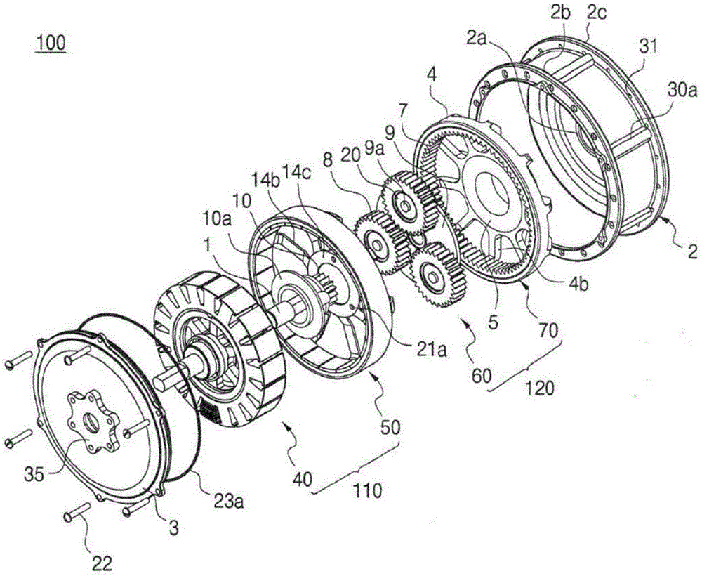
Referring to fig. 2a to 10, a hub driving device 100 for an electric bicycle according to the present invention generally includes a housing 30, a support shaft 1 (draft), a first bearing 6a, a second bearing 6b, a third bearing 6c, a fourth bearing 6d, an electric motor 110 including a rotor 50 and a stator 40, a transmission 120, and a clutch 5.
As shown in fig. 1, in the hub driving device 100 for an electric bicycle according to the present invention, the support shaft 1 is not rotated, both end portions of the support shaft 1 are fixed to the rear fork 232 branched from the frame 230 of the electric bicycle 200, and the electric motor 110 functioning as a power source for generating a rotational force is provided inside the cover 30. The rotational force of the electric motor 110 is transmitted to the transmission 120, which may be formed of a planetary gear device, to reduce the high rotational speed of the motor to a low speed, thereby forming a torque conversion, and then the housing 30 is rotated, i.e., the housing 30 is rotated by being transmitted to the wheels, thereby forming a forward drive. The transmission 120 is a speed reducer for reducing the high rotation speed of the electric motor 110 to a low speed, and functions to convert a low torque output into a high torque output.
Hereinafter, the structure of the hub driving device 100 for an electric bicycle according to the present invention will be described in detail.
The housing 30 of the above-described drive device 100 functioning as a Hub (Hub) includes: a rim 2 provided at the center of the rear wheel 220 and having a cup shape with one side opened; and a circular cover 3 having an outer peripheral portion hermetically coupled to an opening portion of the rim 2. For example, the rim 2 and the cover 3 may be made of a light-weight and strong metal material such as an aluminum alloy, and a through hole through which the support shaft 1 passes may be formed at the center thereof.
Bearing housings are formed inside the through holes of the cover 3 and the rim 2, respectively, and a first bearing 6a and a second bearing 6b are provided so that the housing 30 can be supported to rotate around the support shaft 1.
The first bearing 6a projects outward so that a center portion of the cover 3 forms a brake device installation bracket 35, and forms a bearing housing on an inner side wall thereof, and the clutch fixing portion 2a projecting from the inner side wall of the rim 2 fixes the clutch 5 formed of a one-way bearing on an outer peripheral portion thereof, and the inner peripheral portion thereof functions as a second bearing housing supporting the second bearing 6 b.
The rim 2 has a pair of flange portions 2a and 2c protruding from both sides of the outer peripheral portion of the cup shape, and a plurality of reinforcing portions 30a are connected between the pair of flange portions 2a and 2c to reinforce the strength of the rim 2. As shown in fig. 1, a plurality of spoke attachment holes 31 for fixing a plurality of spokes 226 connected to a rim 224 to which a tire 222 is attached are formed in the pair of flange portions 2a and 2c of the rim 2.
As shown in fig. 8, a groove is formed in the outer peripheral portion of the cover 3, an O-ring 23a for sealing the opening portion of the rim 2 and the outer peripheral portion of the cover 3 is inserted into the groove, and a plurality of fixing bolts 22 are fastened to maintain the assembled state of the rim 2 and the cover 3.
Sealing O- rings 23b and 23c are inserted between the support shaft 1 and the first and second bearings 6a and 6b provided at the centers of the cover 3 and the rim 2, respectively, and sealing O- rings 23d and 23e are inserted between the first and second bearings 6a and 6b and a bearing housing formed on the inner side walls of the cover 3 and the rim 2, respectively.
In particular, as shown in fig. 8, the support shaft 1 is formed with a cable passage 27 through which a cable 292 is passed, the cable 292 being used to transmit a driving signal from a motor driving circuit of the system controller 290 provided outside the housing 30 to the electric motor 110 provided inside.
A brake device installation bracket 35 for braking the rotation of the cover 30 is formed to protrude outside the center of the cover 3 and is integrally formed with the cover 3, and for example, a disc brake may be installed on the bracket 35.
In the description of the illustrated embodiment, the brake device installation bracket 35 is integrally formed on the outer surface of the cover 3, but may be formed on the outer surface of the rim 2.
The hub driving apparatus 100 for an electric bicycle according to the present invention includes an electric motor 110 serving as a power source for generating a rotational force inside the housing 30, and the electric motor 110 may be an outer rotor type in which a single rotor 50 is disposed outside a single stator 40, and may be formed of a radial air gap type (radial air gap type) brushless dc motor, for example.
In the above-described embodiment, the case where the electric motor 110 forms the structure composed of the single stator 40 and the single rotor 50 of the radial air gap type is exemplified, but a single-stator-double-rotor, double-stator-double-rotor structure may be formed.
For example, the electric motor 110 may be driven by a three-phase propagation driving method, and the rotational position detection of the rotor may be performed by an electromagnetic conversion device such as a Hall (Hall) device.
The stator 40 is coupled and fixed at its center portion to the outer periphery of the support shaft 1 by a key 25(key), and rotates the rotor 50 by applying a rotating magnetic field to the rotor 50 based on the rotational position detection of the rotor and a motor drive signal applied from a motor drive circuit.
The rotor 50 has the main magnet 12 laminated on the cylindrical back yoke 13, and the cylindrical back yoke 13 is supported inside the rotor holder 14.
The main magnet 12 may be composed of a plurality of split magnets in which N poles and S poles are alternately arranged, or a cylindrical magnet may be used.
The above-mentioned rotor holder 14 includes: an outer wheel 14a for supporting the cylindrical back yoke 13; an inner ring 14c connected to an extending portion 10a extending from the sun gear 10 forming the transmission 120 by a plurality of fixing bolts 21; and a plurality of connecting ribs 14b for connecting between the outer wheel 14a and the inner wheel 14 c.
The rotor 50 is disposed with its outer peripheral portion spaced apart from the rim 2 of the housing 30 by a predetermined distance, and the output of the rotor 50 is transmitted to the sun gear 10 of the transmission 120 through the rotor holder 14. That is, the rotor 50 and the sun gear 10 may be rotated together about the support shaft 1 by fastening a plurality of fixing bolts 21 between the inner wheel 14c of the rotor bracket 14 and the extension portion 10a of the sun gear 10 and thus connected to each other.
That is, as shown in fig. 3a, the extension portion 10a of the sun gear 10 is formed to be bent from the sun gear 10 in three layers, the inner side of the second-layer bent portion 10b surrounding the support shaft 1 functions as a bearing housing, the third bearing 6c and the fourth bearing 6d are provided in the inner peripheral portion, and the rotor 50 and the sun gear 10 are rotatably supported around the support shaft 1. A spacer ring 28 functioning as a spacer for separating the third bearing 6c and the fourth bearing 6d is inserted between the third bearing 6c and the fourth bearing 6 d. However, the spacer ring 28 may be omitted.
In the extension portion 10a of the sun gear 10, a ring-shaped rotor detection magnet 11 is provided at the third-layer bent portion 10c perpendicular to the support shaft 1, and a plurality of magnetic poles (magnets) corresponding to the main magnets 12 are formed in the rotor detection magnet 11 so as to be able to detect the rotational position of the rotor 50. Therefore, the rotor detection magnet 11 can be rotated simultaneously with the rotation of the rotor 50.
A hall sensor assembly 26 is provided on the stator assembly holder 17 facing the rotor detection magnet 11, and a plurality of hall sensors are attached to the hall sensor assembly 26 at intervals so that the rotational position of the rotor can be detected when the rotor 50 rotates.
The stator 40, which is disposed so as to face the main magnet 12 of the rotor 50 with an air gap therebetween, has an inner peripheral portion fixed to the support shaft 1.
As shown in fig. 10, a stator 40 according to an example of the present invention includes a stator core 15, a stator insulating film 16, first and second stator insulators 16a and 16b, a stator assembly holder 17, and a stator coil 18.
As shown in fig. 9a to 9c, the stator core 15 and the stator assembly holder 17 may be formed in a separate type or may be formed in an integrated type.
As shown in fig. 9c, the stator core 15 has a structure in which a plurality of tooth portions 15b (teeth) (i.e., coil winding portions) extend in a radial direction from an annular yoke 15a (body).
In order to perform insulation, the teeth 15b of the stator core 15 and the yoke 15a (body) are insert-molded with a thermosetting resin such as Bulk Molding Compound (BMC) of polyester or a thermoplastic resin, thereby forming the bobbin and the stator support body to be integrated, instead of the stator insulating film 16 and the first and second stator insulators 16a and 16 b. In this case, the teeth 15b of the stator core 15 may be integrally formed as a bobbin defining a region in which the stator coil 18 is wound, except for a portion facing the main magnet 12 of the rotor.
The insulating bobbin and the stator support may be formed integrally with the stator core 15, and the three-phase (U, V, W) stator coil 18 may be wound after the bobbin is formed separately and assembled. The stator insulating film 16, the first stator insulator 16a, and the second stator insulator 16b can function as an insulating bobbin of a stator or a stator support.
The stator insulating film 16 may be formed of a thin film type insulating film formed in a substantially rectangular cylindrical shape so as to surround four side surfaces except for an outer peripheral surface facing the main magnet 11 of the rotor when the stator core 15 is assembled, and an insulating state is maintained when the coil 18 is wound around the tooth portion 15 b.
The first stator insulator 16a and the second stator insulator 16b are assembled on both sides of the stator core 15 so as to cover the plurality of teeth 15b and the annular yoke 15a from one side and the other side when the coil 18 is wound around the teeth 15b, and are fixed by being engaged with each other. The first stator insulator 16a and the second stator insulator 16b maintain an insulating state together with the stator insulating film 16 when the coil 18 is wound around the tooth portion 15 b.
The first stator insulator 16a and the second stator insulator 16b each include an annular body and a plurality of extending projections extending radially from the annular body so as to correspond to the plurality of teeth 15b and the annular yoke 15 a.
The first stator insulator 16a is formed with an annular extension extending toward the inside of the annular body. In particular, a common terminal for forming a Neutral Point (Neutral Point) when the three-phase (U, V, W) coil 18 is connected in a star (star) connection manner (i.e., Y-connection) is insert-molded into the first stator insulator 16a, so that 3 common terminal terminals can be protruded toward an upper portion of the first stator insulator 16 a.
If necessary, the ring-shaped body of the first stator insulator 16a may be provided with a plurality of winding guide protrusions that serve to guide the coil when the coil is moved to another tooth or the winding direction is switched while maintaining the elastic force for winding the coil around another tooth after one tooth 15b is wound.
Further, U-phase terminal UT, W-contact terminal, and V-contact terminal VT, which are connected to the three-phase (U, V, W) output of inverter circuit 150 (see fig. 11d), may be disposed at intervals on the ring-shaped body of first stator insulator 16 a.
The U-phase terminal UT, the W-phase terminal UT, and the V-phase terminal VT are connected to the first stator insulator 16a by being connected to one of the 3 bus bar fixing nuts. And 3 bus fixing nuts are respectively fastened with bus (bar) bolts. Therefore, the three-phase (U, V, W) output of the inverter circuit 150 is introduced from the outside to the inside of the cover 30 through the cable 292, and then is connected to the 3 bus bar bolts, so that the U-phase terminal UT, the W-phase terminal UT, and the V-phase tab terminal VT can be stably connected.
For example, a Polyurethane Enameled Wire (UEW) coated with Polyurethane or a polyamide Enameled Wire (EIW) coated with polyamide may be used as the metal Wire wound around the teeth to form the stator coil 18.
The stator 40 is connected to the three-phase (U, V, W) stator coil 18 by inserting 3 wires for transmitting a three-phase (U, V, W) driving signal required for driving the motor from the outside of the housing 30 into one cable, introducing the cable into the housing 30, and connecting the cable to the stator.
In this case, the driving device 100 of the present invention may be configured by a split core system, that is, a stator support may be formed simultaneously with the ring-shaped integration of the three-phase (U, V, W) stator coil 18 wound by a plurality of split cores instead of the integrated stator core 15 by injection molding resin.
In the case of the embodiment shown in fig. 10, in which the stator core 15 and the stator assembly holder 17 are separated from each other, the stator 40 may be assembled by assembling the stator insulating film 16, the first stator insulator 16a, and the second stator insulator 16b to the stator core 15 and then, in a state in which the three-phase (U, V, W) stator coil 18 is wound around the teeth 15b, being engaged with the stator assembly holder 17. That is, as shown in fig. 9c, coupling grooves 17g are formed in the outer periphery of the stator assembly holder 17 so as to be parallel to the axial direction, and coupling protrusions 15c that are coupled to the coupling grooves 17g are formed in the inner periphery of the stator core 15 so as to be parallel to the axial direction.
In this case, the stator assembly holder 17 is formed of a metal material, and the outer ring 17c and the inner ring 17a (sleeve) may be connected by a plurality of connecting ribs 17 b. For example, the stator assembly support 17 may be manufactured by die casting using an aluminum alloy or may be formed in a powder metallurgy using a tungsten material.
The plurality of tie bars 17b are provided so as to be biased toward one side so as to form a groove 17h in the stator assembly holder 17 and so as to connect the outer ring 17c and the inner ring 17a (sleeve), and the third bearing 6c and the fourth bearing 6d are accommodated in the groove by extending the extending portion 10a of the sun gear 10, and the rotor detection magnet 11 is disposed on the outer side.
The inner ring 17a (bushing) projects toward the cover 3 so as to ensure a wide contact area when coupled to the support shaft 1.
The stator assembly bracket 17 described above functions as a coupling part for fixing the stator 40 to the support shaft 1. For this, a key groove 17f is formed in a through hole 17e positioned at the center of the stator assembly holder 17 to be coupled to the outer circumference of the support shaft 1 by a key 25.
The stator assembly bracket 17 may be fixedly coupled to the support shaft 1 by a spline coupling manner, in addition to the manner in which the inner wheel 17a (sleeve) is fixed to the support shaft 1 by the key 25 as shown in fig. 3 a.
The stator 40 of the present invention may be formed by laminating a plurality of thin-film silicon steel plates, using an integrated core frame in which the stator core 15 and the stator assembly bracket 17 are integrated. The integrated core frame may be configured such that a plurality of tooth portions 15b radially extend on the outer circumference of the annular yoke 15a, and an inner ring 17a (boss) coupled to the support shaft 1 is connected to the inner side of the annular yoke 15a by a plurality of connecting ribs 17 b.
For example, the hub driving device 100 for an electric bicycle according to the present invention may be configured with an electric motor 110 having a brushless dc structure with a single rotor 50 having 20 poles and a single stator 40 having an 18-slot structure. The stator 40 winds the three-phase (U, V, W) stator coil 18 around the tooth 15b of the stator core 15, and transmits a drive signal to the three-phase (U, V, W) stator coil 18 from a motor drive circuit provided outside or inside the housing 30 via a cable, for example, the drive signal is applied in a 6-step control system.
For example, when the electric motor 110 of the above brushless dc structure is driven in a three-phase (U, V, W) driving manner, the rotational position of the rotor 50 can be detected by using a Hall (Hall) sensor as a rotor position detecting means. Therefore, the rotor detection magnet 11 is provided on the extension portion 10a of the sun gear 10, and when the rotor 50 rotates, the rotational position of the rotor 50 can be detected by the hall sensor assembly 26 facing the detection magnet 11.
For example, the rotor detection magnet 11 has a magnet structure in which 20 poles having the same polarity as the main magnet 12 of the rotor 50 are separately attached while rotating simultaneously with the rotor 50, and magnets having the same polarity are arranged at the same rotation angle as the main magnet 12.
For example, in the case of a three-phase driving method, 2 or 3 hall devices may be used as a rotor position detection device for detecting a position signal of the rotor. The hall sensor assembly 26 may form a structure in which 3 hall sensors and peripheral circuit devices are mounted on a Printed Circuit Board (PCB), may be attached and fixed at a position opposite to the rotor detecting magnet 11, and may be attached and fixed to the stator assembly bracket 17, for example.
The hall sensor assembly 26 can be transmitted to the motor drive circuit by detecting the change in magnetic pole of the rotor detection magnet 11 that rotates in synchronization with the rotation of the rotor 50 by the hall device.
When the hall device of the hall sensor assembly 26 detects the change in the magnetic pole of the rotor detection magnet 19 and transmits the detected change, the control unit of the motor drive circuit generates a drive signal based on the detected change in the magnetic pole, based on a logic table of the 6-step control method described in table 1 in the following.
Further, a cover detection magnet 19 is provided inside the center of the cover 3, and a hall device for detecting whether the cover detection magnet 19 is rotated is attached to the hall sensor assembly 26, so that when the cover is rotated, that is, when the cover 30 is rotated, the detection is performed and the detection is transmitted to the system controller 290 of the electric bicycle.
When the system controller 290 calculates the number of rotations of the cover 30 in accordance with the detection of the number of rotations of the cover detection magnet 19 by the hall sensor assembly 26 and the electric bicycle driving apparatus 100 is used for a power assist system type electric bicycle, the driving of the electric motor 110 can be controlled so that the maximum speed of the electric bicycle is maintained at less than 25 km/h.
Hereinafter, the operation of the electric motor of the present invention will be described with reference to fig. 9a to 11 d.
For example, the electric motor 110 of the present invention is an 18-slot, 20-pole motor, and includes a stator 40 and a rotor 50 disposed outside the stator 40 with a gap therebetween. In the illustrated embodiment, the outer rotor type motor in which the rotor 50 is disposed outside the stator 40 is described as an example, but the present invention is also applicable to an inner rotor type motor in which the rotor is disposed inside the stator.
The rotor 50 may be configured such that a plurality of (20) magnets 211, 212, 213, 214, 215, 216, 217, 218, 219, 220, 221, 222, 223, 224, 225, 226, 227, 228, 229, 230 (i.e., magnetic poles) having different polarities (N-pole and S-pole) are sequentially circularly attached to the back yoke 13.
As shown in fig. 9a and 9c, the stator core 15 has an integral stator core structure in which a plurality of (18) teeth T11, T12, T13, T14, T15, T16, T17, T18, T19, T20, T21, T22, T23, T24, T25, T26, T27, and T28 are radially extended from the annular yoke 15a, or may have a plurality of (18) divided cores in which the front ends are formed in a T shape and the rear ends are connected to each other in an assembled manner.
As described above, in the present invention, the stator core 15 in which the coil is wound and the magnetic circuit path is formed in the stator 40 may use an integrated core or a divided core.
Therefore, except for special cases, for convenience of explanation, the teeth, the split cores, or the slots formed between the teeth are used in the same meaning, and the same reference numerals T11, T12, T13, T14, T15, T16, T17, T18, T19, T20, T21, T22, T23, T24, T25, T26, T27, T28 will be given.
In addition to the 18 slots, 20 poles, the number of magnets (poles) and the number of teeth (slots) of the rotor 50 included in the single-rotor brushless dc electric motor may be combined in various numbers.
Hereinafter, a method of designing a motor in which coils are wound alternately around 3 adjacent teeth (hereinafter, referred to as a "three-wire structure motor") according to the present invention will be described.
First, when designing the three-wire structure motor of the present invention, the slots of the stator and the magnets (magnetic poles) of the rotor can be set in a ratio of 18 slots to 20 magnetic poles as an example. Therefore, in the present invention, the ratio of the number of slots to the number of magnetic poles is different by about 10%, so that the gap between the core and the core (i.e., between the slots) can be set to be narrow by greatly reducing the number of tooth grooves generated when the rotor rotates, as compared with the single-wire connection method, and finally, the efficiency can be improved by increasing the effective area of the magnet and the core (i.e., the tooth portion) facing each other.
The rotor 50 is provided with an annular back yoke 13 at an outer periphery thereof such that N- pole magnets 211, 213, 215, 217, 219, 221, 223, 225, 227, 229 and S- pole magnets 212, 214, 216, 218, 220, 222, 224, 226, 228, 230 are alternately arranged and form a magnetic circuit path between the respective adjacent magnets.
When the stator 40 forms an 18-slot, 20-pole structure, as shown in fig. 11a to 11d, the three-phase (U, V, W) stator coil 18 includes 6 coils U1-U6, W1-W6, V1-V6 in the U-phase, V-phase, and W-phase, respectively, and the coils U1-U6, W1-W6, V1-V6 of the U-phase, V-phase, and W-phase, respectively, form one core group by being continuously wound on adjacent 3 tooth portions, and as a whole, 6 core groups, i.e., a first core group G1, a second core group G2, a third core group G3, a fourth core group G4, a fifth core group G5, and a sixth core group G6 are formed.
Assuming that, in the case that the stator is formed with 27 slots of multiples of 9, each phase includes 9 coils U1-U9, V1-V9, W1-W9, 9 core groups G1, G2, G3, G4, G5, G6, G7, G8, G9 are formed by continuously winding adjacent 3 teeth.
As shown in fig. 11a to 11d, each of the above-described core groups G1, G2, G3, G4, G5, and G6 is annularly arranged on the stator core 15 so as to be continuously wound in 3 teeth of 18 teeth T11, T12, T13, T14, T15, T16, T17, T18, T19, T20, T21, T22, T23, T24, T25, T26, T27, and T28 in this order. Finally, as shown in fig. 11c, the first core group G1 and the fourth core group G4 of the U-phase, the second core group G2 and the fifth core group G5 of the W-phase, and the third core group G3 and the sixth core group G6 of the V-phase are disposed at positions facing each other with the center of the stator core 15 as a reference.
In the stator 40 of the present invention, the three-phase (U, V, W) stator coils U1-U6, W1-W6, and V1-V6 are connected in a Y-connection manner, and as shown in fig. 11d, the stator coils U1-U6, W1-W6, and V1-V6 of the respective U, V, and W phases are connected such that one side (start terminal) of each phase is connected to the U, V, and W phase outputs of the inverter circuit 150 constituting the motor drive circuit, and the other side (end terminal) of each phase is connected to each other to form a Neutral Point (NP).
In this case, when the three-phase (U, V, W) coils U1-U6, W1-W6, and V1-V6 are wired in a Y-wiring manner, a common terminal for forming the neutral point NP is insert-molded to the first stator insulator 16a, and the other side (end terminal) of each phase can be connected to 3 common terminal terminals by projecting 3 common terminal terminals from the common terminal toward the upper portion of the first stator insulator 16 a.
In the 6 core groups G1, G2, G3, G4, G5 and G6 continuously wound around the adjacent 3 teeth, for example, the coils U1, U2 and U3 of the U-phase core group G1 wind the wires around the teeth T11, T12 and T13 in the forward direction, the reverse direction and the forward direction, so that the teeth in the respective core groups generate magnetic flux bundles in the reverse direction.
In the stator 40, drive signals are selectively generated from a control unit (not shown) of the motor drive circuit so that magnetic fluxes in opposite directions are generated between adjacent teeth of up to 18 total teeth T11, T12, T13, T14, T15, T16, T17, T18, T19, T20, T21, T22, T23, T24, T25, T26, T27, and T28, and are applied to the three-phase coils U1-U6, W1-W6, and V1-V6 through the inverter circuit 150.
The U-phase, V-phase, and W-phase coils U1-U6, W1-W6, and V1-V6 are connected in parallel so that the input of each core group is commonly connected to the U-phase, V-phase, and W-phase outputs of the inverter circuit 150, and the output of each core group is commonly connected to 3 common tab terminals C1, C2, and C3 to form a neutral point NP.
That is, the coils U1, U2, U3, U4, U5, U6 of the U phase commonly connect the input and output of the first core group G1 consisting of 3 coils U1, U2, U3 and the fourth core group G4 consisting of 3 coils U4, U5, U6, respectively, and the W-phase coils W1, W2 and V-phase coils V2, V2 are also the same, so that the input and output of the second core group G2 consisting of 3 coils W2, W2 and the fifth core group G4 consisting of 3 coils W2, W2 are commonly connected, respectively, so that the third core group G2 consisting of 3 coils V2, V2 are commonly connected, V2 and V2, V2 are commonly connected, respectively.
As shown in fig. 11c, the stator 40 wound by the three-wire connection method of the present invention may have the first core group G1, the second core group G2, the third core group G3, the fourth core group G4, the fifth core group G5, and the sixth core group G6 arranged in sequence by winding the coils U1-U6, W1-W6, V1-V6 of the U-phase, V-phase, and W-phase phases around 18 teeth T11, T12, T13, T14, T15, T16, T17, T18, T19, T20, T21, T22, T23, T24, T25, T26, T27, and T28.
As shown in fig. 11a, in the present invention, after the first core group G1 of the U phase is wound around the teeth T11, T12, and T13 using one wire, the second core group G2 of the W phase is wound around the teeth T16, T15, and T14, the fifth core group G5 of the W phase is wound around the teeth T23, T24, and T25, the sixth core group G6 of the V phase is wound around the teeth T28, T27, and T26, the third core group G3 of the V phase is wound around the teeth T17, T18, and T19, the fourth core group G4 of the U phase is wound around the teeth T22, T21, and T20, and the coil winding is finished by such continuous winding.
As described above, in the present invention, the winding of the coil can be terminated by continuously winding the U-phase first core group G1 in the tooth portion T11 with one wire until the winding of the tooth portion T20 of the U-phase fourth core group G4 is terminated.
Finally, in the present invention, there is no need for any connection between the coils wound in the 6 teeth in the same phase and between the coils in different phases.
In this case, the winding directions of the coils wound around the 3 teeth included in the core groups G1, G2, G3, G4, G5, and G6 are forward, reverse, and forward. After the coils U1, U2, and U3 of the U-phase first core group G1 are wound, when the coils W3, W2, and W1 of the W-phase second core group G2 are wound, the coils can be wound in a direction from the rear tooth portion T16 toward the front tooth portion T14. Likewise, the fifth core group G5 of the W phase and the sixth core group G6 of the V phase, the third core group G3 of the V phase and the fourth core group G4 of the U phase are also wound with the coil in the same manner.
And, in the process of moving from the coil U3 of the first core group G1 of the U phase to the coil W3 of the second core group G2 of the W phase, one-side winding is performed at one of 3 common tab terminals C1, C2, C3 of a common tab by a wire wrapping (wire wrapping) method, and through this step, one section of the first core group G1 and the second core group G2 is unnaturally connected to the neutral point NP.
In this case, for example, a polyurethane Enameled Wire, a Polyester amide Enameled Wire, or a Polyester Enameled Wire (PEW) coated with polyurethane is used as the metal Wire wound around the teeth to form the coil, and when the common terminal (COM) is wound and then soldered, the metal Wire and the common terminal (COM) are easily electrically connected.
As described above, in the present invention, when the three-phase coil is wound on the tooth portion of the integrated stator core by the three-wire connection method, the coil winding can be formed without a connection portion since the one-time continuous winding is realized for all the coils.
However, the coil winding method of the present invention is not limited thereto, and winding may be performed in divided portions. The core groups are grouped into two adjacent core groups, and for example, two core groups (G1, G2; G3, G4; G5, G6) are wound at a time and wound 3 times by a method of continuously winding 6 adjacent teeth.
As described above, as shown in fig. 11, the electric motor 110 of the present invention has the inputs and outputs of the first core group G1 and the fourth core group G4 of the U-phase commonly connected, respectively, the inputs and outputs of the second core group G2 and the fifth core group G5 of the W-phase commonly connected, respectively, and the inputs and outputs of the third core group G3 and the sixth core group G6 of the V-phase commonly connected, respectively, thereby allowing the coils of the respective phases to form a parallel structure, and thus also minimizing the resistance of the stator coil 18.
In the present invention, when three-phase coils U1 to U6, W1 to W6, and V1 to V6 are wound around teeth T11, T12, T13, T14, T15, T16, T17, T18, T19, T20, T21, T22, T23, T24, T25, T26, T27, and T28 of the stator core, two wires having a small diameter are used for winding. In this case, the inputs and outputs of the respective core groups G1, G2, G3, G4, G5, G6 are commonly connected to the U-phase connection terminal UT, the W-phase connection terminal WT, and the V-phase connection terminal VT and the common connection terminals C1, C2, C3, whereby the resistance of the stator coil 18 can be minimized by constituting a parallel circuit.
In general, the resistance (R) is proportional to the length (l) and inversely proportional to the cross-sectional area (S). Therefore, the total resistance of the stator coils 18 formed in parallel between the respective core groups will be reduced by about 1/2 as compared with the series-connected structure. Further, since the coil loss (coil loss) is a phenomenon that heat is generated by energy generated when a current (I) flows through a conductor having a resistance of R Ω (P ═ I2R), the energy loss causes a temperature increase.
Finally, in the present invention, as the resistance of the stator coil 18 becomes smaller, the resistance and the coil loss are also reduced, so that it is possible to achieve a reduction in the coil temperature and an improvement in the efficiency. Further, since the resistance of the stator coil 18 can be reduced, power increase can be realized in a drive device that requires Instantaneous power (instant power).
In the present invention, two wires having a small diameter are wound, so that a required number of turns (turn) of the coil is secured to achieve a required high rotational speed, thereby improving the performance of the driving device.
Hereinafter, the operation of the electric motor 110 designed according to the three-wire connecting method of the present invention will be described with reference to fig. 11a to 11d and table 1. Table 1 below is a logic table of a control unit (not shown) provided in the motor drive circuit, which is applied when switching devices FET1, FET2, FET3, FET4, FET5, and FET6 of the inverter circuit 150 are selectively activated when the brushless dc electric motor 110 is driven by the 6-step control method.
TABLE 1
The brushless dc electric motor 110 shown in fig. 11c shows a state when the rotational position of the rotor 50 is 0 °, and the direction of the current flowing in the stator coils U1-U6, V1-V6, W1-W6 is switched and applied at each mechanical angle of 12 ° by a 6-step control manner, thereby generating a rotating magnetic field by selectively activating the corresponding stator coils U1-U6, V1-V6, W1-W6.
The motor drive circuit includes a control unit (not shown) and an inverter circuit 150, and the inverter circuit 150 is configured such that 3 pairs of power switching devices FET1, FET2, FET3, FET4, FET5, and FET6 are totem-pole connected to each other, and outputs (U, V, W) of each phase are generated from a connection point between upper Field Effect Transistor (FET) FET1, FET3, FET5, and lower field effect transistor FET4, FET6, and FET2, and are applied to stator coils U1-U6, V1-V6, and W1-W6 of the brushless dc electric motor 110.
In the case of the brushless dc electric motor 110 employing a three-phase driving method, as shown in fig. 11d, the stator 40 includes 6 coils U1-U3, U4-U6, V1-V3, V4-V6, W1-W3, W4-W6 connected in parallel at each, and for example, in the case of forming a star connection structure, the other ends of the coils are connected to each other and form a neutral point NP.
The brushless dc electric motor 110 selectively drives 2 switching devices among 3 pairs of switching devices connected in a totem pole manner based on a position signal of the rotor 50, thereby sequentially applying currents to coils of two phases among U-phase, V-phase, and W-phase coils U1-U3, U4-U6, V1-V3, V4-V6, W1-W3, and W4-W6, and rotating the rotor as the stator coils of the 2 phases are magnetized and a rotating magnetic field is generated. That is, the drive signal is applied from the output of the inverter circuit 150 to the coil of one phase, and is applied to the coil of the other phase through the neutral point NP.
When the hall devices H1, H2, and H3 detect the position signal of the rotor 50 at each angle, the control unit (not shown) of the motor drive circuit causes the inverter circuit 150 to turn on the pair of switching devices and set the current flow path according to table 1.
For example, as shown in fig. 11d, when the hall devices H1, H2, and H3 detect the polarity of the rotor 50 as "N, N, S", the control unit determines that the rotation position of the rotor 50 is 0 ° from table 1, and applies a drive signal to turn on the upper field effect transistor FET3 and the lower field effect transistor FET2, so that current flows to the ground via the FETs 3-parallel V-phase coils V1, V2, V3)/(V4, V5, and V6) -neutral-parallel W-phase coils W3, W2, W1/W6, W5, and W4-FET 2.
As a result, the teeth T17 generate magnetic flux in the inner direction, the teeth T18 generate magnetic flux in the outer direction, and the teeth T19 generate magnetic flux in the inner direction, so that a magnetic circuit as indicated by an arrow is set, and the rotor 50 rotates in the clockwise direction.
That is, in the brushless dc electric motor 110 in fig. 11c, the teeth T17, T18, and T19 of the three-wire connection of the V-phase coils V1, V2, and V3 function as magnets, and are arranged to face the facing magnets 218, 219, and 220 of the rotor 50 with the same polarity as the right side portion of the teeth S-S, N-N, S-S, thereby generating a large repulsive force between the teeth T17, T18, and T19 and the rotor 50.
The left side portions of the teeth are arranged to face the opposing magnets 217, 218, 219 of the rotor 50 in opposite polarities to each other so that the areas are relatively smaller than the right side portions of the teeth T17, T18, T19 in an S-N, N-S, S-N manner, thereby generating a small attractive force between the teeth T17, T18, T19 and the rotor 50.
Therefore, since a small suction force and a large repulsive force are simultaneously generated between the tooth portions T17, T18, T19 and the rotor 50, an action of rotating the rotor 50 in the clockwise direction is generated.
Further, the left side portions of the respective tooth portions of the tooth portions T14, T15, and T16 of the three-wire connections of the W-phase coils W1, W2, and W3 are disposed at the rear end so as to be adjacent to the tooth portions T17-T19 of the three-wire connections of the V-phase coils V1, V2, and V3, and are disposed so as to face the facing magnets 214, 215, and 216 of the rotor 50 with mutually opposite polarities in the manner of N-S, S-N, N-S, and the right side portions of the tooth portions are disposed so as to face the facing magnets 215, 216, and 217 of the rotor 50 with the same polarity in the manner of N-N, S-S, N-N, whereby attraction force and repulsion force are generated between the tooth portions T14, T15, T16 and the rotor 50, and a function of rotating the rotor 50 in the clockwise direction is simultaneously generated.
In addition, the teeth T17, T18, and T19 for connecting three lines of V-phase coils V1, V2, and V3, and the teeth T26, T2, and T28 for connecting three lines of V-phase coils V4, V5, and V6, and the teeth T23, T24, and T25 for connecting three lines of W-phase coils W6, W5, and W4, which are arranged at positions facing the teeth T14, T15, and T16 for connecting three lines of W-phase coils W3, W2, and W1, respectively, generate repulsive force and attractive force with respect to the rotor 50 as described above, and the rotor 50 is rotated in the clockwise direction by the action of pushing and pulling the rotor 50.
Thereafter, as the rotor 50 rotates by a mechanical angle of 12 °, the hall devices H1, H2, and H3 detect the polarity of the rotor 50 as "S, N, S", and the control unit determines that the rotational position of the rotor 50 is the mechanical angle of 12 ° according to table 1. Thus, when the control unit applies a drive signal to turn on the upper FET3 and the lower FET4, current flows to the ground through the FETs 3, the parallel V-phase coils V1, V2, V3/V4, V5, and V6, the neutral point, and the parallel U-phase coils U3, U2, U1/U6, U5, and U4, and the FETs 4.
As described above, in the electric motor 110 of the present invention, each of the core groups G1, G2, G3, G4, G5, G6 forms reverse coil windings in the teeth located in the middle among the continuous 3 teeth of each phase, and the adjacent 2 core groups symmetrically arranged on both sides centering on the rotation axis are activated at each driving step, that is, the continuous 6 teeth of one pair are activated, so that the continuous 3 teeth arranged between the continuous 6 teeth of one pair are not activated.
For example, as shown in fig. 11c, when the rotational position of the rotor 50 is 0 °, the tooth portions T17, T18, T19 (i.e., G3) in which the V-phase coils V1, V2, and V3 are three-wire wired and the tooth portions T14, T15, T16 (i.e., G2) in which the V-phase coils V4, V5, and V5 are three-wire wired are activated, and the tooth portions T5, T5 (i.e., G5) in which the V-phase coils V1, W2, and W3 are three-wire wired and the tooth portions T5, and T5 (i.e., G5) in which the W-phase coils W5, and W5 are three-wire wired are activated, and the tooth portions T5, and T5 (i.e., G5) in which the U-phase coils U5, T5, and T5 are not wired are activated.
In this case, when the driving signal is applied to each of the above-mentioned adjacent 2 core groups to be activated, the 6 teeth parts included in the 2 core groups generate the magnetic flux in the opposite direction. Then, a driving signal is applied from a start terminal of the coil to one core group of the activated adjacent 2 core groups, and a driving signal is applied from an end terminal of the coil to the other core group.
And, of the 6 consecutive teeth that are activated, the left side of the tooth is set to have the opposite polarity to the rotor 50, thereby generating an action of pulling the rotor 50 in the rotational direction by the suction force, and the right side of the tooth is set to have the same polarity as the rotor 50, thereby generating an action of pushing the rotor 50 in the rotational direction by the repulsive force.
That is, 3 consecutive teeth of each of the 4 core groups generate magnetic flux that rotates the magnets of the facing rotors 50 in the same direction, thereby enabling efficient force transmission to the rotors.
Further, in the present invention, since the 6 teeth activated while the 6 consecutive teeth are simultaneously activated generate magnetic flux in the opposite directions, even when the boundary surface between the adjacent S-pole and N-pole magnets is arranged in the rotor 50 facing the teeth of the stator, the rotor 50 can be rotationally driven while effectively setting the magnetic circuit path without magnetic flux loss, and thus the magnets installed by dividing the corners of the adjacent S-pole and N-pole magnets are not arc-processed, so that the effective areas of the magnets 211, 212, 213, 214, 215, 216, 217, 218, 219, 220, 221, 222, 223, 224, 225, 227, 228, 229, 230 facing the teeth T11, T12, T13, T14, T15, T16, T17, T18, T19, T20, T21, T22, T23, T24, T25, T26, T27, T28 can be increased, thereby improving the efficiency.
In the present invention, the coil windings are formed so that magnetic flux beams in opposite directions are generated between adjacent ones of a pair of 6 continuous split cores, and as a drive signal is applied, even if the slot interval between the teeth is set to be small, leakage flux due to the tooth gaps does not occur, and the effective area between the magnet and the core (i.e., the teeth) can be increased to reduce the leakage flux, thereby improving efficiency.
Conventionally, it is necessary to widen the opening (opening) width between the slots and perform the circular arc (R) processing on the outer circumferential surface, but in the present invention, even if the curvature is set so as to match one outer circle formed by all 18 teeth without performing the circular arc processing on each tooth, the tooth gap is not largely generated. Finally, the magnetic flux leakage can be reduced by maximizing the effective area between the magnet and the core (tooth portion), so that the efficiency can be improved.
The electric motor 110 of the present invention can continuously perform all coil windings at once when winding the three-phase coil in the tooth portion of the integrated stator core by the three-wire connection method, and thus can form the coil windings without a connection portion. In this case, in the embodiment shown in fig. 11c, the respective core groups G1, G2, G3, G4, G5, G6 are wound in such a manner that they are arranged in the clockwise direction in the order of G1 to G6 in the teeth portions T11, T12, T13, T14, T15, T16, T17, T18, T19, T20, T21, T22, T23, T24, T25, T26, T27, T28 of the stator core, but the core groups may also be arranged in the counterclockwise direction in the order of G1-G3-G5-G4-G6-G2.
In the description of the embodiment shown in fig. 11a, when the coils are wound in the teeth portions T11, T12, T13, T14, T15, T16, T17, T18, T19, T20, T21, T22, T23, T24, T25, T26, T27, and T28 of the stator core, the winding is performed in the order of G1-G2-G5-G6-G3-G4, which is exemplified, but the core group may be arranged in the order of G1-G3-G5-G4-G6-G2 and the coils may be wound in the order of G1-G2-G5-G3-G6-G4.
As shown in fig. 11c, in the present invention, the 3-winding coils are arranged in the order of the U-phase core group, the W-phase core group, and the V-phase core group, but the 3-winding coils may be arranged in the order of the U-phase core group, the V-phase core group, and the W-phase core group.
Hereinafter, the structure of the transmission 120 of the hub driving device 100 for an electric bicycle according to the present invention will be described in detail.
The transmission 120 is a speed reducer for reducing the high rotation speed of the electric motor 110 to the low rotation speed, and may be formed of a single planetary gear device or a multi-speed transmission device that performs a fixed ratio transmission.
The fixed ratio change planetary gear device applied to the transmission 120 of the hub driving device 100 for an electric bicycle according to the present invention includes a sun gear 10, a plurality of pinion gears 8, a ring gear 7, and a carrier 9. In the case where the planetary gear device is formed in a structure in which the sun gear input, the ring gear output, and the carrier are fixed, a reverse deceleration output of which the reduction ratio (-) is determined by the number of teeth of the ring gear/the number of teeth of the sun gear is obtained.
The transmission 120 of the present invention will transmit the rotor 50 output of the electric motor 110 to the sun gear 10 connected by the spider 14. That is, the interconnection is achieved by fastening a plurality of fixing bolts 21 between the inner wheel 14c of the spider 14 and the extension portion 10a extending from the sun gear 10.
A pair of third and fourth bearings 6c and 6d are provided between the extension portion 10a and the support shaft 1, and the central portion of the sun gear 10 is coupled to be rotatable about the support shaft 1, so that when the rotor 50 is rotated by the rotating magnetic field of the stator 40, the sun gear 10 is rotated in the same direction as the rotor 50.
3 planetary gears 8 are coupled to the outer circumference of the sun gear 10, the 3 planetary gears 8 are rotatably supported by separate rotary shafts 9a through bearings 20, respectively, and one ends of the 3 rotary shafts 9a are fixed to a carrier 9 (i.e., a planetary carrier). Therefore, as shown in fig. 5, the above-described 3 planetary gears 8 and the carrier 9 (i.e., the planetary gear holder) are integrated, thereby forming a planetary gear assembly 60.
Also, the carrier 9 (i.e., a planetary carrier) has a central portion thereof fixedly coupled to the outer periphery of the support shaft 1 in a keyed manner using a key 25 to prevent rotation.
Therefore, the 3 planetary gears 8 are configured to rotate around the rotation shaft 9a with the rotation of the sun gear 10 but not to idle, and when the sun gear 10 rotates in one direction (for example, Clockwise (CW) direction), the 3 planetary gears 8 rotate in the opposite direction (that is, counterclockwise (CCW) direction).
The 3 planetary gears 8 are inscribed in the ring gear 7 and are gear-coupled, and the outer periphery of the ring gear 7 is gear-coupled to the ring gear holder 4. The above-described ring gear bracket 4 includes: an outer ring 4a that houses and supports the ring gear 7; an inner wheel 4c formed in a smaller circular shape than the outer wheel 4 a; and a plurality of connecting ribs 4b for connecting between the outer wheel 4a and the inner wheel 4 c. The above-described ring gear 7 and the ring gear carrier 4 are integrated to form the ring gear assembly 70.
A clutch 5 formed of a one-way bearing is provided between the inner ring 4c of the ring gear carrier 4 and the housing 30, that is, between the inner ring 4c of the ring gear carrier 4 and the annular clutch fixing portion 2a extending from the inner space of the rim 2. That is, the outer race of the one-way bearing is connected to the inner race 4c of the ring gear carrier 4, and the inner race of the one-way bearing is connected to the clutch fixing portion 2 a.
For example, the Clutch 5 has a structure in which a One-Way Clutch (One-Way Clutch) and a ball bearing are incorporated, and an outer ring and an inner ring are provided to the inner ring 4c of the ring gear holder 4 and the Clutch fixing portion 2a by press fitting or key fixing, respectively. Also, the one-way Clutch may employ a Cam Clutch (Cam Clutch).
When the above-mentioned 3 pinion gears 8 rotate (for example, in the Clockwise (CW) direction), the ring gear 7 and the ring gear carrier 4 will make a rotation in the same direction (clockwise (CW) direction) as the pinion gears 8.
Hereinafter, the operation of the hub driving device 100 for an electric bicycle according to the present invention will be described.
First, the speed-adjusting handlebar electric bicycle is an electric bicycle equipped with a speed-adjusting handlebar such as an accelerator whose motor output can be arbitrarily controlled by a driver.
When the driving apparatus 100 of the present invention is applied to a speed-controlled electric bicycle with a rotating handle, after a user operates a Power switch on an operation panel 284 of the electric bicycle 200 to turn on the electric motor 110, and then accelerates the speed by operating an accelerator 282 provided in a handlebar, the rotor 50 and the rotor holder 14 are simultaneously rotated in a Clockwise (CW) direction by the driving of the electric motor 110, and in synchronization with this, the sun gear 10 of the transmission 120 is also rotated in a Clockwise (CW) direction around the support shaft 1.
Therefore, the 3 pinion gears 8 gear-coupled to the sun gear 10 will rotate counterclockwise (CCW), and the ring gear 7 and the ring gear holder 4 gear-coupled thereto will rotate counterclockwise (CCW) in the same manner as the pinion gears 8.
The counterclockwise (CCW) rotation of the ring gear carrier 4 causes the rim 2, that is, the cover 30 to rotate counterclockwise (CCW), by the clutch 5 formed of a one-way bearing.
As described above, since the transmission 120 is constituted by a single planetary gear device forming a structure in which the input of the sun gear 10, the output of the ring gear 7, and the carrier 9 are fixed, the reduction ratio (-) is determined by the number of ring gears/the number of sun gears, and the counterclockwise (CCW) output of the reverse speed reduction is generated with respect to the Clockwise (CW) output of the electric motor 110.
Finally, the rim 224 and the tire 222 connected to the housing 30 by the plurality of spokes 226 also rotate in the counterclockwise direction (CCW), so that the electric bicycle 200 will travel in the forward direction.
In the speed-controlled handle-type electric bicycle 200, if the rotation speed of the electric motor 110 is increased in proportion to the operation of the accelerator 282, the rotation speed transmitted to the cover 30 via the transmission 120 is also increased in proportion to the increase in rotation speed, and the running speed of the electric bicycle is increased.
On the other hand, when a user gets off the electric bicycle 200 and puts the electric bicycle in a parking place, the electric bicycle can be manually moved forward while the electric motor 110 is turned off (turn-off).
In this case, when the electric bicycle is advanced in a state where the electric motor 110 is turned off, the housing 30 rotates counterclockwise (CCW), and the clutch 5 formed of a one-way bearing rotating in the same direction as the housing 30 transmits the rotational force of the housing 30 to the ring gear carrier 4.
Finally, when the electric bicycle is advanced while the electric motor 110 is in the off state, the clutch 5 blocks the rotation of the ring gear carrier 4 and the ring gear 7, and the planetary gear device of the transmission 120 and the electric motor 110 maintain the stopped state.
When the user gets off the electric bicycle with the electric motor 110 turned off and then manually moves the electric bicycle backward, the housing 30 rotates in the Clockwise (CW) direction. In this case, the clutch 5 transmits the Clockwise (CW) rotational force of the cover 30 to the ring gear carrier 4, and the planetary gear 8 rotates in the Clockwise (CW) direction as the ring gear carrier 4 and the ring gear 7 rotate in the clockwise direction. The sun gear 10 rotates counterclockwise (CCW) about the support shaft 1 by the Clockwise (CW) rotation of the planetary gear 8.
The counter-clockwise (CCW) rotation of the sun gear 10 causes the rotor holder 14 and the rotor 50 of the electric motor 110 to simultaneously rotate in the counter-clockwise (CCW) direction, causing the rotor 50 to act as a load. However, such low-speed backing does not cause damage to the drive or cause noise.
As described above, in the present invention, the ring gear 7 and the ring gear holder 4 are separated from the housing 30, and the clutch 5 formed of a one-way bearing is connected between the ring gear holder 4 and the clutch fixing portion 2a protruding from the housing 30, so that the output of the ring gear 7 can be transmitted to the housing 30 only when the electric motor 110 is operated (turned on), and the transmission of the rotational force of the housing 30 to the ring gear 7 can be blocked even if the housing 30 is rotated in the forward direction when the electric motor 110 is stopped (turned off).
Finally, in the present invention, when a user gets off the electric bicycle in a motor stopped state and then places the electric bicycle in a parking place or runs out of a battery or pedals the bicycle by the user according to the user's needs and moves the bicycle in a forward direction, that is, when the cover 30 rotates in the forward direction, the rotation of the ring gear 7 can be blocked, so that the gear breakage of the planetary gear device or the generation of noise can be prevented.
In particular, the driving device 100 of the present invention is applicable to a power assist system type electric bicycle and an electric bicycle having both a speed-adjusting handle type and a power assist system type, in addition to a speed-adjusting handle type electric bicycle.
For example, when the driving device 100 of the present invention is used in a power-assisted electric bicycle, when a user selects a mode based on a road running environment by operating a power switch on the operation panel 284 and pushes the pedal 240, a pedal force applied to the pedal 240 is measured by a torque sensor provided on the crank shaft 252 and transmitted to the system controller 290.
The system controller 290 will turn on the electric motor 110 when the pedal force of the foot pedal 240 is detected by the torque sensor. In the booster-type electric bicycle 200, when the pedal force applied to the pedal plate 240 is measured and the pedal force applied to the pedal plate is increased, the system controller 290 increases the output of the electric motor 110, and finally, the rotation speed transmitted to the cover 30 via the transmission 120 is also made proportional to the increase in the output of the electric motor 110, and the running speed of the electric bicycle 200 is also increased.
Therefore, the power assist system type electric bicycle 200 can actively control the output of the electric motor 110 of the electric bicycle by the driver adjusting the pedal force applied to the pedal plate 240.
When traveling on an uphill slope, the output of the electric motor 110 of the electric bicycle may be increased by measuring the pedal force applied to the pedal plate 240 by the torque sensor, so that the traveling speed may be maintained at the same level as when traveling on a flat ground.
The hall sensor provided in the hall sensor assembly 26 calculates the rotation speed of the electric motor 110, that is, the traveling speed of the electric bicycle 200, based on the rotation speed of the detection cover detection magnet 19, and displays the result on the operation panel 284 when the rotation speed is transmitted to the system controller 290.
The maximum running speed of the power-assisted system type electric bicycle specified in the system is less than 25km/h, so that the bicycle can run on a bicycle lane. Therefore, in the assistive system electric bicycle 200, in order to satisfy the bicycle lane running condition, when the rotation speed of the electric motor 110 calculated based on the rotation detection of the cover detection magnet 19 detected by the hall sensor provided in the hall sensor assembly 26 exceeds 25km/h, that is, when the running speed of the electric bicycle exceeds 25km/h, the system controller 290 can control the electric motor 110 to stop operation or the running speed of the electric bicycle to not exceed 25 km/h.
In the booster system type electric bicycle, when a user gets off the electric bicycle and puts the electric bicycle in a parking place or runs out a battery or pedals the electric bicycle according to the user's needs and moves the electric bicycle in a forward direction in a state where the power switch is turned off (off mode in which the support of the electric motor is completely blocked), the rotational force of the cover 30 is blocked by the clutch 5 and is not transmitted to the ring gear holder 4 and the ring gear 7. Finally, the planetary gear device of the transmission 120 and the electric motor 110 can be maintained in a stopped state, and gear breakage or noise generation can be prevented.
In particular, when the user gets off the electric bicycle with the electric motor 110 turned off and then backs up the electric bicycle, the housing 30 rotates in the Clockwise (CW) direction. In this case, the clutch 5 transmits the Clockwise (CW) rotational force of the cover 30 to the ring gear carrier 4, and the planetary gear 8 rotates in the Clockwise (CW) direction as the ring gear carrier 4 and the ring gear 7 rotate in the clockwise direction. The sun gear 10 rotates counterclockwise (CCW) about the support shaft 1 by the Clockwise (CW) rotation of the planetary gear 8.
The counter-clockwise (CCW) rotation of the sun gear 10 causes the rotor holder 14 and the rotor 50 of the electric motor 110 to simultaneously rotate in the counter-clockwise (CCW) direction, causing the rotor 50 to act as a load. However, such low-speed backing does not cause damage to the drive or cause noise.
Industrial applicability
The driving device of the invention can be suitable for speed-regulating rotating handle type electric bicycles, power-assisted system type electric bicycles and electric bicycles with speed-regulating rotating handle type and power-assisted system type.