CN113566112B - Low-energy-consumption chlorine gas supply station and using method - Google Patents
Low-energy-consumption chlorine gas supply station and using method Download PDFInfo
- Publication number
- CN113566112B CN113566112B CN202110910135.1A CN202110910135A CN113566112B CN 113566112 B CN113566112 B CN 113566112B CN 202110910135 A CN202110910135 A CN 202110910135A CN 113566112 B CN113566112 B CN 113566112B
- Authority
- CN
- China
- Prior art keywords
- liquid chlorine
- chlorine
- tank
- liquid
- vaporizer
- Prior art date
- Legal status (The legal status is an assumption and is not a legal conclusion. Google has not performed a legal analysis and makes no representation as to the accuracy of the status listed.)
- Active
Links
Images


Classifications
-
- F—MECHANICAL ENGINEERING; LIGHTING; HEATING; WEAPONS; BLASTING
- F17—STORING OR DISTRIBUTING GASES OR LIQUIDS
- F17C—VESSELS FOR CONTAINING OR STORING COMPRESSED, LIQUEFIED OR SOLIDIFIED GASES; FIXED-CAPACITY GAS-HOLDERS; FILLING VESSELS WITH, OR DISCHARGING FROM VESSELS, COMPRESSED, LIQUEFIED, OR SOLIDIFIED GASES
- F17C7/00—Methods or apparatus for discharging liquefied, solidified, or compressed gases from pressure vessels, not covered by another subclass
- F17C7/02—Discharging liquefied gases
- F17C7/04—Discharging liquefied gases with change of state, e.g. vaporisation
-
- F—MECHANICAL ENGINEERING; LIGHTING; HEATING; WEAPONS; BLASTING
- F17—STORING OR DISTRIBUTING GASES OR LIQUIDS
- F17C—VESSELS FOR CONTAINING OR STORING COMPRESSED, LIQUEFIED OR SOLIDIFIED GASES; FIXED-CAPACITY GAS-HOLDERS; FILLING VESSELS WITH, OR DISCHARGING FROM VESSELS, COMPRESSED, LIQUEFIED, OR SOLIDIFIED GASES
- F17C13/00—Details of vessels or of the filling or discharging of vessels
Landscapes
- Engineering & Computer Science (AREA)
- Mechanical Engineering (AREA)
- General Engineering & Computer Science (AREA)
- Feeding, Discharge, Calcimining, Fusing, And Gas-Generation Devices (AREA)
- Filling Or Discharging Of Gas Storage Vessels (AREA)
Abstract
本发明涉及一种低能耗氯气供应站及使用方法,包括液氯计量罐、液氯汽化器、液氯应急倒液罐和液氯排渣罐,液氯汽化器列管底部低于液氯计量罐筒体底部,液氯汽化器列管顶部高于液氯计量罐筒体顶部;液氯计量罐底部的液氯出口通过液氯输送管与液氯汽化器底部的液氯进口连接;液氯应急倒液罐位于液氯计量罐下方,液氯计量罐的应急排出口与液氯应急倒液罐的液氯进口连接,液氯应急倒液罐的液氯出口与液氯汽化器底部的液氯进口连接;液氯排渣罐位于液氯汽化器下方,液氯汽化器底部排净口与液氯排渣罐连接。本申请可依靠液位差将液氯计量罐内的液氯输送至液氯汽化器内,取消了现有的液氯输送泵,可减少氯气的泄漏点,有效降低了供应氯气工艺系统的能耗。
The invention relates to a low-energy chlorine gas supply station and its use method, comprising a liquid chlorine metering tank, a liquid chlorine vaporizer, a liquid chlorine emergency pouring tank and a liquid chlorine slag discharge tank, the bottom of the tubes of the liquid chlorine vaporizer being lower than the liquid chlorine metering tank The bottom of the liquid chlorine vaporizer tube is higher than the top of the liquid chlorine metering tank; the liquid chlorine outlet at the bottom of the liquid chlorine metering tank is connected to the liquid chlorine inlet at the bottom of the liquid chlorine vaporizer through the liquid chlorine delivery pipe; the liquid chlorine emergency pouring tank Located below the liquid chlorine metering tank, the emergency outlet of the liquid chlorine metering tank is connected to the liquid chlorine inlet of the liquid chlorine emergency pouring tank, and the liquid chlorine outlet of the liquid chlorine emergency pouring tank is connected to the liquid chlorine inlet at the bottom of the liquid chlorine vaporizer; The chlorine slag discharge tank is located under the liquid chlorine vaporizer, and the bottom drain port of the liquid chlorine vaporizer is connected to the liquid chlorine slag discharge tank. This application can rely on the liquid level difference to transport the liquid chlorine in the liquid chlorine metering tank to the liquid chlorine vaporizer, cancel the existing liquid chlorine delivery pump, reduce the leakage point of chlorine gas, and effectively reduce the energy consumption of the process system for supplying chlorine gas .
Description
技术领域technical field
本发明涉及氯气供应技术领域,尤其涉及一种低能耗氯气供应站及使用方法。The invention relates to the technical field of chlorine gas supply, in particular to a chlorine gas supply station with low energy consumption and a use method.
背景技术Background technique
氯气是一种气体单质。常温常压下为黄绿色,有强烈刺激性气味的剧毒气体,具有窒息性 ,密度比空气大。可溶于水和碱溶液,易溶于有机溶剂(如四氯化碳),难溶于饱和食盐水。氯气易压缩,可液化为黄绿色的油状液氯,是氯碱工业的主要产品之一,可用作为强氧化剂。Chlorine is an elemental gas. It is yellow-green under normal temperature and pressure. It is a highly toxic gas with a strong pungent smell. It is suffocating and has a higher density than air. Soluble in water and alkali solution, easily soluble in organic solvents (such as carbon tetrachloride), hardly soluble in saturated saline. Chlorine gas is easy to compress and can be liquefied into yellow-green oily liquid chlorine. It is one of the main products of the chlor-alkali industry and can be used as a strong oxidant.
氯气能与有机物和无机物进行取代反应和加成反应生成多种氯化物,主要用于生产塑料(如PVP)、合成纤维、染料、农药、消毒剂、漂白剂溶剂以及各种氯化物。Chlorine can undergo substitution and addition reactions with organic and inorganic substances to generate a variety of chlorides, which are mainly used in the production of plastics (such as PVP), synthetic fibers, dyes, pesticides, disinfectants, bleach solvents and various chlorides.
为便于运输和贮存,通常需要将氯气液化。使用时,再将液氯汽化成气体。In order to facilitate transportation and storage, it is usually necessary to liquefy chlorine gas. When in use, the liquid chlorine is vaporized into a gas.
目前,通常使用液氯泵输送液氯至汽化设备。然而,用液氯泵输送液氯,不仅需要消耗电能,而且液氯泵需要周期性的清理、检修,劳动强度大。At present, liquid chlorine pumps are usually used to transport liquid chlorine to vaporization equipment. However, using a liquid chlorine pump to transport liquid chlorine not only consumes electric energy, but also requires periodic cleaning and maintenance of the liquid chlorine pump, which is labor-intensive.
发明内容Contents of the invention
本申请为了解决上述技术问题提供一种低能耗氯气供应站及使用方法。In order to solve the above technical problems, the present application provides a low energy consumption chlorine gas supply station and its usage method.
本申请通过下述技术方案实现:The application is realized through the following technical solutions:
一种低能耗氯气供应站,包括液氯计量罐和液氯汽化器,液氯汽化器列管底部低于液氯计量罐筒体底部,液氯汽化器列管顶部高于液氯计量罐筒体顶部;A low-energy chlorine gas supply station, comprising a liquid chlorine metering tank and a liquid chlorine vaporizer, the bottom of the tubes of the liquid chlorine vaporizer is lower than the bottom of the cylinder of the liquid chlorine metering tank, and the top of the tubes of the liquid chlorine vaporizer is higher than the top of the cylinder of the liquid chlorine metering tank;
液氯计量罐底部的液氯出口通过液氯输送管与液氯汽化器底部的液氯进口连接。The liquid chlorine outlet at the bottom of the liquid chlorine metering tank is connected with the liquid chlorine inlet at the bottom of the liquid chlorine vaporizer through a liquid chlorine delivery pipe.
进一步的,液氯计量罐水平设置,液氯汽化器竖直设置,液氯汽化器上封头顶端高于液氯计量罐筒体顶部。Further, the liquid chlorine metering tank is arranged horizontally, the liquid chlorine vaporizer is arranged vertically, and the top end of the upper head of the liquid chlorine vaporizer is higher than the top of the cylinder body of the liquid chlorine metering tank.
进一步的,液氯汽化器下封头低端低于液氯计量罐筒体底部。Further, the lower end of the lower head of the liquid chlorine vaporizer is lower than the bottom of the cylinder body of the liquid chlorine metering tank.
优选地,液氯汽化器列管顶部安装标高高出液氯计量罐筒体顶部安装标高300mm以上;Preferably, the installation elevation of the top of the liquid chlorine vaporizer column tube is higher than the installation elevation of the top of the liquid chlorine metering tank by more than 300mm;
液氯汽化器列管底部安装标高低于液氯计量罐筒体底部安装标高300mm以上;The installation elevation of the bottom of the liquid chlorine vaporizer tube is lower than the installation elevation of the bottom of the liquid chlorine metering tank by more than 300mm;
液氯汽化器上封头顶端安装标高高出液氯计量罐筒体顶部安装标高1200mm以上;The installation elevation of the top of the upper head of the liquid chlorine vaporizer is higher than the installation elevation of the top of the liquid chlorine metering tank by more than 1200mm;
液氯汽化器下封头低端安装标高低于液氯计量罐筒体底部安装标高900mm以上。The installation elevation of the lower end of the lower head of the liquid chlorine vaporizer is lower than the installation elevation of the bottom of the liquid chlorine metering tank by more than 900mm.
进一步的,液氯输送管为U型,液氯汽化器的液氯进口管道上设置液相止回阀。Further, the liquid chlorine delivery pipe is U-shaped, and a liquid phase check valve is arranged on the liquid chlorine inlet pipe of the liquid chlorine vaporizer.
进一步的,低能耗氯气供应站还包括液氯应急倒液罐和液氯排渣罐,液氯应急倒液罐位于液氯计量罐下方,液氯计量罐底部的应急排出口与液氯应急倒液罐的液氯进口连接,液氯应急倒液罐的液氯出口与液氯汽化器底部的液氯进口连接;Further, the low-energy chlorine gas supply station also includes a liquid chlorine emergency pouring tank and a liquid chlorine slag discharge tank. The liquid chlorine inlet of the liquid tank is connected, and the liquid chlorine outlet of the liquid chlorine emergency pouring tank is connected with the liquid chlorine inlet at the bottom of the liquid chlorine vaporizer;
液氯排渣罐位于液氯汽化器下方,液氯汽化器底部排净口与液氯排渣罐连接。The liquid chlorine slag discharge tank is located under the liquid chlorine vaporizer, and the bottom drain port of the liquid chlorine vaporizer is connected with the liquid chlorine slag discharge tank.
优选地,液氯应急倒液罐全容积不小于液氯计量罐全容积,液氯排渣罐全容积不小于液氯汽化器管程总容积。Preferably, the total volume of the liquid chlorine emergency pouring tank is not less than the total volume of the liquid chlorine metering tank, and the total volume of the liquid chlorine slag discharge tank is not less than the total volume of the liquid chlorine vaporizer tube side.
进一步的,液氯汽化器和液氯应急倒液罐通过管道连接压缩空气缓冲罐。Further, the liquid chlorine vaporizer and the liquid chlorine emergency dump tank are connected to the compressed air buffer tank through pipelines.
优选地,液氯计量罐筒体底部安装标高高于液氯应急倒液罐筒体顶部安装标高900mm以上;Preferably, the installation elevation of the bottom of the liquid chlorine metering tank is higher than the installation elevation of the top of the liquid chlorine emergency pouring tank by more than 900mm;
液氯排渣罐顶部管口安装标高低于液氯汽化器底部排净口标高300mm以上。The installation elevation of the nozzle at the top of the liquid chlorine slag discharge tank is more than 300mm lower than the elevation of the bottom discharge port of the liquid chlorine vaporizer.
与现有技术相比,本申请具有以下有益效果:Compared with the prior art, the present application has the following beneficial effects:
1,本申请可依靠液位差将液氯计量罐内的液氯输送至液氯汽化器内,取消了现有的液氯输送泵,可减少氯气的泄漏点,有效降低了供应氯气工艺系统的能耗;1. This application can rely on the liquid level difference to transport the liquid chlorine in the liquid chlorine metering tank to the liquid chlorine vaporizer, cancel the existing liquid chlorine delivery pump, reduce the leakage point of chlorine gas, and effectively reduce the cost of the process system for supplying chlorine gas. energy consumption;
2,当液氯计量罐出现险情,泄露液氯或氯气时,可通过位差把液氯计量罐内的液氯全部倒入备用的液氯应急倒液罐内,能有效控制液氯的泄露量。2. When the liquid chlorine metering tank is in danger and leaks liquid chlorine or chlorine gas, all the liquid chlorine in the liquid chlorine metering tank can be poured into the spare liquid chlorine emergency pouring tank through the potential difference, which can effectively control the leakage of liquid chlorine quantity.
附图说明Description of drawings
此处所说明的附图用来提供对本申请实施方式的进一步理解,构成本申请的一部分,并不构成对本发明实施方式的限定。The drawings described here are used to provide a further understanding of the embodiments of the present application, constitute a part of the application, and do not limit the embodiments of the present invention.
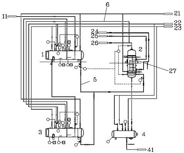
图1是液氯计量罐、液氯汽化器、液氯应急倒液罐和液氯排渣罐的位置布置图;Figure 1 is a layout diagram of the liquid chlorine metering tank, liquid chlorine vaporizer, liquid chlorine emergency pouring tank and liquid chlorine slag discharge tank;
图2是本发明的低能耗氯气供应站的管线示意图。Fig. 2 is a schematic diagram of the pipeline of the low energy consumption chlorine gas supply station of the present invention.
具体实施方式Detailed ways
为使本申请的目的、技术方案和优点更加清楚,下面将结合实施方式中的附图,对本发明实施方式中的技术方案进行清楚、完整地描述。显然,所描述的实施方式是本发明一部分实施方式,而不是全部的实施方式。通常在此处附图中描述和示出的本发明实施方式的组件可以以各种不同的配置来布置和设计。In order to make the purpose, technical solutions and advantages of the present application clearer, the technical solutions in the embodiments of the present invention will be clearly and completely described below in conjunction with the drawings in the embodiments. Apparently, the described embodiments are some but not all of the embodiments of the present invention. The components of the embodiments of the invention generally described and illustrated in the figures herein may be arranged and designed in a variety of different configurations.
因此,以下对在附图中提供的本发明的实施方式的详细描述并非旨在限制要求保护的本发明的范围,而是仅仅表示本发明的选定实施方式。基于本发明中的实施方式,本领域普通技术人员在没有作出创造性劳动前提下所获得的所有其他实施方式,都属于本发明保护的范围。Accordingly, the following detailed description of the embodiments of the invention provided in the accompanying drawings is not intended to limit the scope of the claimed invention, but merely represents selected embodiments of the invention. Based on the implementation manners in the present invention, all other implementation manners obtained by persons of ordinary skill in the art without creative efforts fall within the protection scope of the present invention.
需要说明的是,在不冲突的情况下,本发明中的实施方式及实施方式中的特征可以相互组合。需要说明的是,本说明书中的各个实施例均采用递进的方式描述,每个实施例重点说明的都是与其他实施例的不同之处,各个实施例之间相同相似的部分互相参见即可。It should be noted that, in the case of no conflict, the embodiments and features in the embodiments of the present invention can be combined with each other. It should be noted that each embodiment in this specification is described in a progressive manner, and each embodiment focuses on the differences from other embodiments. For the same and similar parts in each embodiment, refer to each other, that is, Can.
应注意到:相似的标号和字母在下面的附图中表示类似项,因此,一旦某一项在一个附图中被定义,则在随后的附图中不需要对其进行进一步定义和解释。It should be noted that like numerals and letters denote similar items in the following figures, therefore, once an item is defined in one figure, it does not require further definition and explanation in subsequent figures.
在本发明的描述中,需要说明的是,术语“上”、“下”、 “竖直”、“水平”等指示的方位或位置关系为基于附图所示的方位或位置关系,或者是该发明产品使用时惯常摆放的方位或位置关系,或者是本领域技术人员惯常理解的方位或位置关系,仅是为了便于描述本发明和简化描述,而不是指示或暗示所指的装置或元件必须具有特定的方位、以特定的方位构造和操作,因此不能理解为对本发明的限制。In the description of the present invention, it should be noted that the orientation or positional relationship indicated by the terms "upper", "lower", "vertical", "horizontal" etc. is based on the orientation or positional relationship shown in the drawings, or is The usual orientation or positional relationship of the product of the invention in use, or the orientation or positional relationship commonly understood by those skilled in the art, is only for the convenience of describing the present invention and simplifying the description, rather than indicating or implying the referred device or element Must be in a particular orientation, be constructed in a particular orientation, and operate in a particular orientation, and therefore should not be construed as limiting the invention.
在本发明的描述中,还需要说明的是,除非另有明确的规定和限定,术语“设置”、“安装”、“相连”、“连接”应做广义理解,例如,可以是固定连接,也可以是可拆卸连接,或一体地连接;可以是机械连接,也可以是电连接;可以是直接相连,也可以通过中间媒介间接相连,可以是两个元件内部的连通。对于本领域的普通技术人员而言,可以具体情况理解上述术语在本发明中的具体含义。In the description of the present invention, it should also be noted that, unless otherwise clearly specified and limited, the terms "installation", "installation", "connection" and "connection" should be understood in a broad sense, for example, it may be a fixed connection, It can also be a detachable connection or an integral connection; it can be a mechanical connection or an electrical connection; it can be a direct connection or an indirect connection through an intermediary, and it can be the internal communication of two components. Those of ordinary skill in the art can understand the specific meanings of the above terms in the present invention in specific situations.
实施例1Example 1
如图1、图2所示,本实施例公开的低能耗氯气供应站,包括液氯计量罐1和液氯汽化器2。As shown in FIG. 1 and FIG. 2 , the low-energy chlorine gas supply station disclosed in this embodiment includes a liquid chlorine metering tank 1 and a
本实施例中液氯计量罐1水平设置,液氯汽化器2竖直设置。液氯汽化器2下封头低端低于液氯计量罐1筒体底部。液氯汽化器2列管27底部低于液氯计量罐1筒体底部;液氯汽化器2上封头顶端高于液氯计量罐1筒体顶部。液氯汽化器2列管27顶部高于液氯计量罐1筒体顶部。In this embodiment, the liquid chlorine metering tank 1 is arranged horizontally, and the
液氯计量罐1底部的液氯出口通过液氯输送管5与液氯汽化器2底部的液氯进口连接。液氯输送管5为U型。The liquid chlorine outlet at the bottom of the liquid chlorine metering tank 1 is connected to the liquid chlorine inlet at the bottom of the
液氯汽化器2的液氯进口管道上设置液相止回阀,以此避免液氯倒流,防止液氯计量罐1受到三氯化氮污染。A liquid phase check valve is provided on the liquid chlorine inlet pipeline of the
在另一个实施例中,低能耗氯气供应站还包括水平设置的液氯应急倒液罐3和液氯排渣罐4。液氯应急倒液罐3位于液氯计量罐1下方,液氯计量罐1底部的应急排出口与液氯应急倒液罐3的液氯进口连接,液氯应急倒液罐3的液氯出口与液氯汽化器2底部的液氯进口连接。In another embodiment, the low energy consumption chlorine gas supply station further includes a liquid chlorine
作为优选,液氯应急倒液罐3的液氯出口通过三通与液氯输送管5相连,继而实现与液氯汽化器2的连接。液氯应急倒液罐3全容积不小于液氯计量罐1全容积。Preferably, the liquid chlorine outlet of the liquid chlorine
液氯排渣罐4位于液氯汽化器2下方,液氯汽化器2底部排净口与液氯排渣罐4连接,液氯排渣罐4全容积要不小于液氯汽化器2管程总容积。The liquid
液氯汽化器2和液氯应急倒液罐3通过管道连接压缩空气缓冲罐21。液氯计量罐1、液氯应急倒液罐3、液氯排渣罐4通过管道连接真空缓冲罐23。The
本实施例的氯气供应站配置双塔双泵双风机事故氯气收集处理系统22。The chlorine gas supply station in this embodiment is equipped with an emergency chlorine gas collection and treatment system 22 with two towers, two pumps and two fans.
实施例2Example 2
液氯计量罐1筒体底部安装标高要高于液氯应急倒液罐3筒体顶部安装标高900mm以上,以此保证液氯应急倒液过程畅通,快速。The installation elevation of the bottom of liquid chlorine metering tank 1 is higher than the installation elevation of the top of liquid chlorine
液氯汽化器2列管顶部安装标高要高出液氯计量罐1筒体顶部安装标高300mm以上,以此保证液氯计量罐1的液氯在有效液位范围内汽化。The installation elevation of the top of the
液氯汽化器2列管底部安装标高要低于液氯计量罐1筒体底部安装标高300mm以上,以此保证液氯计量罐1的液氯在有效液位范围内汽化。The installation elevation of the bottom of the
液氯汽化器2上封头顶端安装标高要高出液氯计量罐1筒体顶部安装标高1200mm以上,以此保证汽化器内产生的氯气不夹带液氯,有效完成汽液分离。The installation elevation of the top of the upper head of the
液氯汽化器2下封头低端安装标高要低于液氯计量罐1筒体底部安装标高900mm以上,以此避免液氯计量罐1内的液氯烧干。The installation elevation of the lower head of the
液氯排渣罐4顶部管口安装标高要低于液氯汽化器2底部排净口标高300mm以上,以此保证汽化器排渣过程畅通,快速。The installation elevation of the nozzle at the top of the liquid chlorine
本发明的氯气供应站的室内地坪要有厚度600mm以上的实体围挡,以此防止氯气供应站内部泄露的氯气无组织扩散。The indoor floor of the chlorine gas supply station of the present invention must have a solid enclosure with a thickness of more than 600mm, so as to prevent the chlorine gas leaked from inside the chlorine gas supply station from distributing without organization.
液氯计量罐1、液氯汽化器2、液氯应急倒液罐3间设有气相平衡管道6。The liquid chlorine metering tank 1, the
本发明的使用方法,如下:The using method of the present invention is as follows:
S1,卸车S1, unloading
1.1试生产方案通过验收后,方可进行试生产首次开车。1.1 After the trial production plan has passed the acceptance, the trial production can be started for the first time.
用液氯专用鹤管11衔接好液氯计量罐1与液氯槽车上的气相总管和液相总管,并缓慢打开液氯液相阀,使液氯槽车内的液氯缓慢进入液氯计量罐1内。在首次开车过程中,当液氯槽车与液氯计量罐1压力平衡时,可以缓慢打开液氯计量罐1泄压阀,以此保证卸车作业需要的压力差。Connect the liquid chlorine metering tank 1 with the gas phase main pipe and the liquid phase main pipe on the liquid chlorine tank car with the
1.2液氯槽车内的液氯卸车作业进行到一半时,开启卸车液氯汽化器2,用卸车液氯汽化器2产生的氯气加压液氯槽车内气相空间,以此步骤完成液氯槽车后半程卸车作业。1.2 When the liquid chlorine unloading operation in the liquid chlorine tank car is halfway through, open the unloading
S2,汽化,可通过以下两种方式控制。S2, vaporization, can be controlled in the following two ways.
2.1液氯计量罐1内的液氯在液位差(U型管原理)作用下通过液氯输送管道5灌入液氯汽化器2内。2.1 The liquid chlorine in the liquid chlorine metering tank 1 is poured into the
液氯汽化器2的导热油进口连接导热油循环泵24,液氯汽化器2的导热油出口连接导热油循环罐25,通过控制液氯汽化器2内通入的热载体的流量、温度,调整液氯汽化器2液氯汽化速度及汽化压力。在此过程中提前打开液氯计量罐1与液氯汽化器2间的气相平衡管道6。The heat transfer oil inlet of
2.2液氯计量罐1内的液氯通过液氯输送管道5灌入液氯汽化器2内时,通过控制液氯汽化器2内通入的液氯液位高度,调整液氯汽化速度及汽化压力。2.2 When the liquid chlorine in the liquid chlorine metering tank 1 is poured into the
在此过程中要提前打开液氯计量罐1与液氯汽化器2间的气相平衡管道。During this process, the gas phase balance pipeline between the liquid chlorine metering tank 1 and the
在液氯汽化过程中,液氯所含三氯化氮持续浓缩、富集。需要定期检测液氯汽化器2内液氯中的三氯化氮浓度。在三氯化氮允许含量上限范围内,液氯汽化器2底部液氯要定期排放至液氯排渣罐4内待处理。液氯排渣罐4内的液氯通过氯气真空系统抽走部分液氯后,其余含高浓度三氯化氮的液氯进碱液中和系统41内中和,实现无害化处理。During the vaporization process of liquid chlorine, nitrogen trichloride contained in liquid chlorine is continuously concentrated and enriched. It is necessary to regularly detect the concentration of nitrogen trichloride in the liquid chlorine in the
在液氯计量罐1出现险情,泄露液氯或氯气时,可通过位差把液氯计量罐1内的液氯全部倒入备用的液氯应急倒液罐3内,可有效控制液氯的泄露量。When there is a dangerous situation in the liquid chlorine metering tank 1 and liquid chlorine or chlorine gas leaks, all the liquid chlorine in the liquid chlorine metering tank 1 can be poured into the spare liquid chlorine
而液氯应急倒液罐3内的液氯通过压缩空气或氮气加压提升至液氯汽化器2内汽化。And the liquid chlorine in the liquid chlorine
液氯汽化器2产生的氯气经顶部氯气出口排至氯气缓冲罐26,再送至用户。氯气缓冲罐26设置有液氯触点报警装置,如氯气缓冲罐26内灌入液氯,立即切断液氯汽化器2液氯来源。The chlorine gas produced by the
其中,各设备的操作温度和操作压力如表1所示。Among them, the operating temperature and operating pressure of each equipment are shown in Table 1.
表1:工作压力及工作温度表Table 1: Working pressure and working temperature table

本发明可依靠液位差将液氯计量罐1内的液氯输送至液氯汽化器2内,取消了现有的液氯输送泵,可减少氯气的泄漏点,有效降低了供应氯气工艺系统的能耗。The invention can rely on the liquid level difference to transport the liquid chlorine in the liquid chlorine metering tank 1 to the
以上所述的具体实施方式,对本申请的目的、技术方案和有益效果进行了进一步详细说明,所应理解的是,以上所述仅为本发明的具体实施方式而已,并不用于限定本发明的保护范围,凡在本发明的精神和原则之内,所做的任何修改、等同替换、改进等,均应包含在本发明的保护范围之内。The specific embodiments described above have further described the purpose, technical solutions and beneficial effects of the present application in detail. It should be understood that the above descriptions are only specific embodiments of the present invention, and are not intended to limit the scope of the present invention. Protection scope, within the spirit and principles of the present invention, any modification, equivalent replacement, improvement, etc., shall be included in the protection scope of the present invention.
Claims (1)
Priority Applications (1)
| Application Number | Priority Date | Filing Date | Title |
|---|---|---|---|
| CN202110910135.1A CN113566112B (en) | 2021-08-09 | 2021-08-09 | Low-energy-consumption chlorine gas supply station and using method |
Applications Claiming Priority (1)
| Application Number | Priority Date | Filing Date | Title |
|---|---|---|---|
| CN202110910135.1A CN113566112B (en) | 2021-08-09 | 2021-08-09 | Low-energy-consumption chlorine gas supply station and using method |
Publications (2)
| Publication Number | Publication Date |
|---|---|
| CN113566112A CN113566112A (en) | 2021-10-29 |
| CN113566112B true CN113566112B (en) | 2023-01-24 |
Family
ID=78171051
Family Applications (1)
| Application Number | Title | Priority Date | Filing Date |
|---|---|---|---|
| CN202110910135.1A Active CN113566112B (en) | 2021-08-09 | 2021-08-09 | Low-energy-consumption chlorine gas supply station and using method |
Country Status (1)
| Country | Link |
|---|---|
| CN (1) | CN113566112B (en) |
Family Cites Families (7)
| Publication number | Priority date | Publication date | Assignee | Title |
|---|---|---|---|---|
| DE112005002548T5 (en) * | 2004-10-15 | 2008-09-18 | Climax Molybdenum Co., Phoenix | Apparatus and method for producing a gaseous fluid |
| FR2891347B1 (en) * | 2005-09-28 | 2007-11-02 | Air Liquide | METHOD AND DEVICE FOR FILLING A PRESSURIZED GAS IN A RESERVOIR |
| CN202708586U (en) * | 2012-08-08 | 2013-01-30 | 沈阳东方钛业有限公司 | Liquid chlorine gasification system |
| CN202746928U (en) * | 2012-08-31 | 2013-02-20 | 张路 | Liquid supply system |
| CN207814920U (en) * | 2017-11-03 | 2018-09-04 | 重庆厚海能源设备制造有限公司 | A kind of LNG liquid addition mechanism without immersed pump and precooling |
| CN207702116U (en) * | 2017-12-05 | 2018-08-07 | 宜宾海丰和锐有限公司 | A kind of liquid chlorine vaporization system |
| CN108224078A (en) * | 2018-01-16 | 2018-06-29 | 中科睿凌江苏低温设备有限公司 | A kind of air energy low-temperature liquid gas is without pump loading system |
-
2021
- 2021-08-09 CN CN202110910135.1A patent/CN113566112B/en active Active
Also Published As
| Publication number | Publication date |
|---|---|
| CN113566112A (en) | 2021-10-29 |
Similar Documents
| Publication | Publication Date | Title |
|---|---|---|
| US20230192516A1 (en) | Dynamic produced water treatment apparatus and system | |
| US8128792B2 (en) | Fluorine gas generator | |
| CN108201711A (en) | A kind of decompression degasser | |
| CN113566112B (en) | Low-energy-consumption chlorine gas supply station and using method | |
| WO2019227328A1 (en) | Household alcohol-based fuel supply system | |
| KR102041132B1 (en) | Chlorine dioxide manufacturing device and manufacturing method for removed from explosion dangeri with power-free decompression material supply and reaction | |
| SE9904808L (en) | Process and apparatus for cleaning porous materials by carbon dioxide | |
| US20200339452A1 (en) | Dynamic produced water treatment apparatus and system with oxygen recovery | |
| US20160195076A1 (en) | Process and unit for pumping flammable products capable of forming an explosive atmosphere | |
| CN112413395B (en) | Liquid ammonia delivery system and method | |
| CN108486549B (en) | Material recovery device | |
| CN105148714A (en) | Acidic waste gas treatment device | |
| KR20110132448A (en) | Gas supply method and apparatus | |
| CN207192958U (en) | A kind of oil field produced water treatment facilities | |
| CN101124169A (en) | Method and device for generating sterilizing water with hypochlorous acid or chlorous acid as main component | |
| JP2006068742A (en) | Ozone on-line injection, reuse, and destruction system | |
| CN204611339U (en) | A kind of with discharging and the bilateral Gas feeding gas control panel connect | |
| JPH105741A (en) | Vacuum deaerator | |
| US10150202B2 (en) | Small automatic polishing liquid cleaning device for rigid gas permeable contact lens | |
| EP2568243B1 (en) | Vapour phase drying apparatus | |
| JPS6025515A (en) | Apparatus for removing component dissolved in oil | |
| CN220697813U (en) | Medicament box device system for in-situ remediation of contaminated sites | |
| JP2005024068A (en) | Feeder of halogen gas or halogen-contained gas | |
| JP2005061636A (en) | Halogen gas or halogen containing gas supply method, cleaning method for semiconductor manufacturing device cleaning room, surface treatment method using halogen gas or halogen containing gas, semiconductor manufacturing device, and surface treatment device | |
| CN214456986U (en) | A self-gas circulation multi-stage pressure type dissolved air flotation skid device |
Legal Events
| Date | Code | Title | Description |
|---|---|---|---|
| PB01 | Publication | ||
| PB01 | Publication | ||
| SE01 | Entry into force of request for substantive examination | ||
| SE01 | Entry into force of request for substantive examination | ||
| TA01 | Transfer of patent application right |
Effective date of registration: 20220325 Address after: 200000 1st floor, 1990 Jinbi Road, Fengxian District, Shanghai Applicant after: Huamengxin (Shanghai) Project Management Co.,Ltd. Address before: 010010 Aohua building, block B, fortune times, Wulanchabu West Street, Saihan District, Hohhot City, Inner Mongolia Autonomous Region Applicant before: Aohua Engineering Technology Co.,Ltd. |
|
| TA01 | Transfer of patent application right | ||
| TA01 | Transfer of patent application right |
Effective date of registration: 20221227 Address after: 010000 Aohua Building, Block B, Fortune Times, Ulanqab West Street, Saihan District, Hohhot, Inner Mongolia Autonomous Region Applicant after: Aohua Engineering Technology Co.,Ltd. Address before: 200000 1st floor, 1990 Jinbi Road, Fengxian District, Shanghai Applicant before: Huamengxin (Shanghai) Project Management Co.,Ltd. |
|
| TA01 | Transfer of patent application right | ||
| GR01 | Patent grant | ||
| GR01 | Patent grant |