CN113607049A - Heat dissipation type explosion-proof structure of laser scanner - Google Patents
Heat dissipation type explosion-proof structure of laser scanner Download PDFInfo
- Publication number
- CN113607049A CN113607049A CN202110778599.1A CN202110778599A CN113607049A CN 113607049 A CN113607049 A CN 113607049A CN 202110778599 A CN202110778599 A CN 202110778599A CN 113607049 A CN113607049 A CN 113607049A
- Authority
- CN
- China
- Prior art keywords
- explosion
- proof
- heat dissipation
- shell
- laser scanner
- Prior art date
- Legal status (The legal status is an assumption and is not a legal conclusion. Google has not performed a legal analysis and makes no representation as to the accuracy of the status listed.)
- Granted
Links
- 230000017525 heat dissipation Effects 0.000 title claims abstract description 46
- 238000010521 absorption reaction Methods 0.000 claims abstract description 6
- 125000006850 spacer group Chemical group 0.000 claims description 29
- 238000007789 sealing Methods 0.000 claims description 16
- 230000001012 protector Effects 0.000 claims description 10
- 230000008859 change Effects 0.000 claims description 5
- 238000010276 construction Methods 0.000 claims description 2
- 239000007789 gas Substances 0.000 description 15
- 229920001971 elastomer Polymers 0.000 description 5
- QVGXLLKOCUKJST-UHFFFAOYSA-N atomic oxygen Chemical compound [O] QVGXLLKOCUKJST-UHFFFAOYSA-N 0.000 description 4
- 230000000694 effects Effects 0.000 description 4
- 239000002360 explosive Substances 0.000 description 4
- 239000001301 oxygen Substances 0.000 description 4
- 229910052760 oxygen Inorganic materials 0.000 description 4
- 238000009825 accumulation Methods 0.000 description 3
- 238000013461 design Methods 0.000 description 3
- 239000000463 material Substances 0.000 description 3
- 230000005855 radiation Effects 0.000 description 3
- 239000005341 toughened glass Substances 0.000 description 3
- CURLTUGMZLYLDI-UHFFFAOYSA-N Carbon dioxide Chemical compound O=C=O CURLTUGMZLYLDI-UHFFFAOYSA-N 0.000 description 2
- RYGMFSIKBFXOCR-UHFFFAOYSA-N Copper Chemical compound [Cu] RYGMFSIKBFXOCR-UHFFFAOYSA-N 0.000 description 2
- 238000004891 communication Methods 0.000 description 2
- 229910052802 copper Inorganic materials 0.000 description 2
- 239000010949 copper Substances 0.000 description 2
- 239000003822 epoxy resin Substances 0.000 description 2
- 238000004880 explosion Methods 0.000 description 2
- 238000009434 installation Methods 0.000 description 2
- 230000007246 mechanism Effects 0.000 description 2
- 238000000034 method Methods 0.000 description 2
- 229920000647 polyepoxide Polymers 0.000 description 2
- 229910001220 stainless steel Inorganic materials 0.000 description 2
- 239000010935 stainless steel Substances 0.000 description 2
- 238000012546 transfer Methods 0.000 description 2
- IJGRMHOSHXDMSA-UHFFFAOYSA-N Atomic nitrogen Chemical compound N#N IJGRMHOSHXDMSA-UHFFFAOYSA-N 0.000 description 1
- 239000004593 Epoxy Substances 0.000 description 1
- XEEYBQQBJWHFJM-UHFFFAOYSA-N Iron Chemical compound [Fe] XEEYBQQBJWHFJM-UHFFFAOYSA-N 0.000 description 1
- 229920000459 Nitrile rubber Polymers 0.000 description 1
- 239000000853 adhesive Substances 0.000 description 1
- 230000001070 adhesive effect Effects 0.000 description 1
- 230000004075 alteration Effects 0.000 description 1
- 230000004888 barrier function Effects 0.000 description 1
- 230000009286 beneficial effect Effects 0.000 description 1
- 229910002092 carbon dioxide Inorganic materials 0.000 description 1
- 239000001569 carbon dioxide Substances 0.000 description 1
- 238000005266 casting Methods 0.000 description 1
- 238000005260 corrosion Methods 0.000 description 1
- 230000007797 corrosion Effects 0.000 description 1
- 229910001873 dinitrogen Inorganic materials 0.000 description 1
- 239000000428 dust Substances 0.000 description 1
- 238000005516 engineering process Methods 0.000 description 1
- 239000004519 grease Substances 0.000 description 1
- 230000020169 heat generation Effects 0.000 description 1
- 238000004519 manufacturing process Methods 0.000 description 1
- 238000005259 measurement Methods 0.000 description 1
- 238000000691 measurement method Methods 0.000 description 1
- 239000002184 metal Substances 0.000 description 1
- 229910052751 metal Inorganic materials 0.000 description 1
- 238000005065 mining Methods 0.000 description 1
- 239000000203 mixture Substances 0.000 description 1
- 238000012986 modification Methods 0.000 description 1
- 230000004048 modification Effects 0.000 description 1
- 238000000465 moulding Methods 0.000 description 1
- 239000003973 paint Substances 0.000 description 1
- 238000005192 partition Methods 0.000 description 1
- 239000003208 petroleum Substances 0.000 description 1
- 229920001296 polysiloxane Polymers 0.000 description 1
- 230000002265 prevention Effects 0.000 description 1
- 230000008569 process Effects 0.000 description 1
- 238000002791 soaking Methods 0.000 description 1
- 239000000126 substance Substances 0.000 description 1
- 238000004381 surface treatment Methods 0.000 description 1
- 238000009864 tensile test Methods 0.000 description 1
- 238000002834 transmittance Methods 0.000 description 1
Images


Classifications
-
- G—PHYSICS
- G01—MEASURING; TESTING
- G01B—MEASURING LENGTH, THICKNESS OR SIMILAR LINEAR DIMENSIONS; MEASURING ANGLES; MEASURING AREAS; MEASURING IRREGULARITIES OF SURFACES OR CONTOURS
- G01B11/00—Measuring arrangements characterised by the use of optical techniques
- G01B11/002—Measuring arrangements characterised by the use of optical techniques for measuring two or more coordinates
-
- G—PHYSICS
- G01—MEASURING; TESTING
- G01B—MEASURING LENGTH, THICKNESS OR SIMILAR LINEAR DIMENSIONS; MEASURING ANGLES; MEASURING AREAS; MEASURING IRREGULARITIES OF SURFACES OR CONTOURS
- G01B11/00—Measuring arrangements characterised by the use of optical techniques
- G01B11/24—Measuring arrangements characterised by the use of optical techniques for measuring contours or curvatures
Landscapes
- Physics & Mathematics (AREA)
- General Physics & Mathematics (AREA)
- Connector Housings Or Holding Contact Members (AREA)
Abstract
The invention provides a heat dissipation type explosion-proof structure of a laser scanner, which comprises a shell, wherein a heat dissipation module is arranged in the shell and comprises a heat absorption sheet, one end of the heat absorption sheet is provided with a heat conduction pipe, the outside of the shell is provided with a heat dissipation structure, the heat conduction pipe is connected with the heat dissipation structure so as to conduct heat in the shell to the outside of the shell, one end of the shell is provided with a top cover, the heat conduction pipe is connected with the inner side of the top cover, and the heat dissipation structure is arranged on the outer side of the top cover; the problem of the explosion-proof performance is low because the heat dissipation is not smooth in traditional three-dimensional laser scanner is solved.
Description
Technical Field
The invention relates to the field of laser scanners, in particular to a heat dissipation type explosion-proof structure of a laser scanner.
Background
The three-dimensional laser scanner rapidly acquires three-dimensional coordinate data of the surface of the measured object in a large area and high resolution manner by a high-speed laser scanning measurement method, breaks through the traditional single-point measurement manner, and has the unique advantages of high efficiency and high precision. The three-dimensional laser scanning technology can provide three-dimensional point cloud data of a scanned object surface, so that the method can be used for obtaining a high-precision and high-resolution digital model and is widely applied to the fields of mining industry, petroleum industry, chemical industry, military industry, navigation, traffic and the like.
General laser scanner equipment, rotary mechanism leakproofness is poor, the connection reliability between each module cavity is not high, simultaneously, because laser generator during operation produces a large amount of heats, the instrument itself can the temperature be higher, if the heat dissipation is untimely, can cause the temperature accumulation, when meetting special environment, if there is dangerous easily fire explosive gas in the colliery environment in the pit, once the scanner has sealed not hard up problem, light then burns out internal element, heavily light gas, therefore traditional equipment that only has single flame proof function hardly reaches explosion-proof, the safe handling requirement of dust prevention etc. see CN 112859041A explosion-proof structure and contain the laser scanner of this explosion-proof structure and the structure of record in using thereof, this structure is mainly through the explosion-proof mode of sealed flame proof, but neglects the heat dissipation problem of laser self.
Disclosure of Invention
The invention provides a heat dissipation type explosion-proof structure of a laser scanner, which solves the problem of low explosion-proof performance of the traditional three-dimensional laser scanner caused by unsmooth heat dissipation.
In order to solve the technical problems, the technical scheme adopted by the invention is as follows: the utility model provides a laser scanner heat dissipation formula explosion-proof construction, includes the shell, is equipped with the heat dissipation module in the shell, and the heat dissipation module includes the heat absorption piece, and heat absorption piece one end is equipped with the heat pipe, and the shell outside is equipped with heat radiation structure, and the heat pipe is connected so that the heat conduction in the shell outside to the shell with heat radiation structure.
In the preferred scheme, shell one end is equipped with the top cap, and the heat pipe is connected with the top cap inboard, and heat radiation structure establishes in the top cap outside.
In the preferred scheme, the explosion-proof wall-penetrating device further comprises a rotating base, a rotatable turntable is arranged at one end of the rotating base and is connected with the end portion of the shell, an explosion-proof cavity is formed in the other end of the rotating base, an explosion-proof wall-penetrating terminal is further arranged, one end of the explosion-proof wall-penetrating terminal is arranged in the explosion-proof cavity, and the other end of the explosion-proof wall-penetrating terminal penetrates through the outer wall of the rotating base and enters the inside of the rotating base.
In the preferred scheme, the side wall of the explosion-proof cavity is provided with a cable leading-in device, the cable leading-in device is communicated with the inside of the explosion-proof cavity so that the cable penetrates into the explosion-proof cavity, and explosion-proof mud is filled between the cable leading-in device and the cable.
In a preferable scheme, a first bulge and a second bulge are arranged on the outer edge of the rotary table, a clamping groove is formed between the first bulge and the second bulge, and an extending part is arranged on the outer edge of the rotary base and inserted into the clamping groove.
In the preferred scheme, the inner side of the extension part is provided with a sinking groove, a rotary sealing piece is arranged in the sinking groove, and the two side sides of the rotary sealing piece respectively abut against the bottom of the sinking groove and the first bulge.
In a preferred scheme, an explosion-proof window is arranged on the side wall of the shell, and a soft gasket is arranged between the explosion-proof window and the side wall of the shell.
In a preferred scheme, the casing is also filled with deoxygenated gas, and the pressure inside the casing is higher than the pressure outside the casing.
In the preferred scheme, the inside explosion-proof protector that still is equipped with of shell, explosion-proof protector includes the connector, and the connector both ends are equipped with connecting terminal, and the connector middle part is equipped with the slidable spacer, and two connecting terminal pass through the spacer to be connected, still are equipped with the cavity shell, are equipped with sealed chamber in the cavity shell, and a pot head of cavity shell has the slidable piston, piston and spacer end connection, and the outside atmospheric pressure of cavity shell changes and makes the spacer slide so that two connecting terminal break or switch on.
In a preferable scheme, an insulating block is further arranged in the connector, conductive lugs are arranged at two ends of the insulating block and connected with connecting terminals, contact terminals are arranged at two sides of a spacer and are in sliding sleeve connection with the insulating block, one end of each contact terminal abuts against the spacer, a spring is arranged at the other end of each contact terminal, the end part of each spring abuts against the conductive lug, the spacer is provided with a through hole, and the two contact terminals are in contact and conduction through sliding of the spacer;
the shell lateral wall is equipped with the observation window, and the spacer tip still is equipped with a plurality of scale grooves, and it has the deoxidier that discolours to fill in the scale groove.
The invention has the beneficial effects that: the surface heat dissipation structure is more excellent than a point heat dissipation structure, so that the internal temperature accumulation of the scanner is prevented, and the safety coefficient is improved; the explosion-proof cavity is used for placing a main circuit part and further preventing explosion by sealing and isolating external gas; the design of a curved structure is adopted, the sealing mechanism is ingenious, and the risk of sealing failure is reduced; the shell is made of stainless steel, so that the shell can bear the explosive force in the scanner and prevent the internal explosive flame and high-temperature gas from igniting the external explosive gas mixture through the explosion-proof gap; the inner cavity of the shell is sealed with gas with stable property and without oxygen, and is pressurized to improve the heat conduction efficiency and simultaneously has the effect of preventing external oxygen from entering; the explosion-proof protector is arranged and connected in series to a circuit of the scanner, and when the internal cavity is sealed and fails, the circuit is broken, so that the explosion-proof effect is achieved.
Drawings
The invention is further illustrated by the following figures and examples.
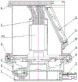
FIG. 1 is a schematic of the present invention.
Fig. 2 is a cross-sectional view of the present invention.
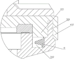
Fig. 3 is a view of the structure of the labyrinth seal of the present invention.
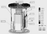
Fig. 4 is a cloud of heat dissipation temperatures of the present invention.
Figure 5 is a schematic view of the position of the explosion protection protector of the present invention.
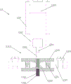
Fig. 6 is a schematic structural view of the explosion-proof protector of the present invention.
In the figure: an explosion-proof chamber 1; the explosion-proof wall-penetrating terminal 2; a rotating base 3; an overhang 301; a sink tank 302; a turntable 4; a first protrusion 401; a second protrusion 402; a heat dissipation module 5; a heat absorbing sheet 501; a top cover 6; a heat dissipation structure 601; a cable lead-in 7; a rotary seal 8; a roller bearing 9; a housing 10; an observation window 1001; a pressurizing valve 1002; a soft pad 11; an explosion-proof window 12; an explosion-proof protector 13; a cavity housing 1301; a piston 1302; a sealed cavity 1303; a septum 1304; a through hole 1305; a scale groove 1306; a color-changing deoxidizer 1307; an insulating block 1308; a connection terminal 1309; a conductive ear 1310; a spring 1311; contact terminals 1312; a connector 1313.
Detailed Description
As shown in fig. 1-6, a heat dissipation type explosion-proof structure for a laser scanner includes a hollow housing 10, a heat dissipation module 5 is disposed in the housing 10, the heat dissipation module 5 includes a heat sink 501, a heat pipe is disposed at one end of the heat sink 501, a heat dissipation structure 601 is disposed outside the housing 10, and the heat pipe is connected to the heat dissipation structure 601 to conduct heat in the housing 10 to the outside of the housing 10, thereby effectively avoiding heat accumulation.
The internal heat dissipation module 5 is arranged on the circuit board, silicone grease with high heat conductivity coefficient is arranged on components with large heat productivity, the heat dissipation module is designed with a unique closed vacuum cavity soaking plate to change a point heat source into a surface heat source, and the working medium closed in the cavity repeatedly carries out physical phase change to transfer heat; a plurality of heat pipes are designed to be in contact with the top cover 6 through a heat conducting medium, the top cover 6 is made of copper, copper has good heat conductivity and higher heat conductivity, and the outer surface is plated to prevent the heat pipes from being easily rusted; the maximum temperature of the surface of the shell is not more than 110 ℃ through software analysis, and the heat can be effectively dissipated in the sealed cavity.
In a preferred scheme, a top cover 6 is arranged at one end of the shell 10, the heat conduction pipe is connected with the inner side of the top cover 6, and the heat dissipation structure 601 is arranged on the outer side of the top cover 6.
In the preferred scheme, still include rotating base 3, 3 one end of rotating base is equipped with rotatable revolving stage 4, the two is connected and rotate relatively through roller bearing 9, revolving stage 4 and 10 end connection of shell, make shell 10 can 360 horizontal rotations, shell 10 design has the seal groove, be equipped with oil-resistant type rubber circle, fix through screw bolt tightening and realize IP54 protection level, the 3 other end of rotating base is equipped with explosion-proof chamber 1, still be equipped with explosion-proof wall-penetrating terminal 2, explosion-proof wall-penetrating terminal 2 one end is arranged in explosion-proof chamber 1, the explosion-proof wall-penetrating terminal 2 other end passes inside 3 outer walls of rotating base get into rotating base 3, 2 inside communication mesons of explosion-proof wall-penetrating terminal and insulating barrier both ends are sealed with epoxy.
In the preferred scheme, 1 lateral wall in explosion-proof chamber is equipped with cable introducing device 7, and in cable introducing device 7 and 1 inside intercommunication in explosion-proof chamber so that the cable penetrates explosion-proof chamber 1, the aviation cable of 7 preferred of cable introducing device and rubber circle pass through the joint clamp fastening and fix, fills explosion-proof mud between cable introducing device 7 and the cable, satisfies mechanical strength, tensile test and electrical property.
The explosion-proof cavity 1 at the bottom is connected with the cable lead-in device 7 to form a threaded explosion-proof joint surface, and a rubber ring and a plug sheet are arranged in the explosion-proof cavity to achieve an explosion-proof effect, so that the explosion-proof cavity is long in service life and good in sealing performance.
In a preferred scheme, a design of a curved sealing structure is adopted, a first protrusion 401 and a second protrusion 402 are arranged on the outer edge of the rotary table 4, a clamping groove is arranged between the first protrusion 401 and the second protrusion 402, an extension portion 301 is arranged on the outer edge of the rotary base 3, and the extension portion 301 is inserted into the clamping groove.
In a preferred scheme, a sunken groove 302 is formed in the inner side of the extension portion 301, a rotary sealing member 8 is arranged in the sunken groove 302, the material is preferably nitrile rubber, two sides of the rotary sealing member 8 abut against the bottom of the sunken groove 302 and the first protrusion 401 respectively, the rotary sealing member 8 is designed into a proper material and shape, the rotary sealing member is fixed by the internal tension of a rubber body, the installation is convenient, the sealing is close to a flexible lip edge, relatively small contact pressure is applied to a friction surface, but the sealing function is kept enough, the contact pressure is reduced along with the increase of the speed, the friction loss and the heat generation are kept to be minimum, and the service life is good.
In the preferred scheme, the side wall of the shell 10 is provided with an explosion-proof window 12, the explosion-proof window 12 is made of integrally formed toughened glass, a soft gasket 11 is fixedly arranged between the toughened glass and a metal piece, the surface of the joint surface of the shell 10 and the explosion-proof window 12 is pretreated firstly, the bonding binding force between two materials is increased, the inner wall of the window of the shell 10 is uniformly coated with a special adhesive to seal and fix the toughened glass, and the light transmittance and the explosion-proof surface treatment are ensured.
In the preferred scheme, casing 10 still is filled with deoxidization gas, for example carbon dioxide, nitrogen gas etc, the shell 10 lateral wall is equipped with pressure valve 1002, be used for the one-way inside gas of filling to casing 10, the inside sealed condition that is of casing 10, even when partial seal became invalid, inflammable gas such as outside gas got into, also can be because oxygen concentration is low, can't be lighted, the inside atmospheric pressure of casing 10 is higher than the outside atmospheric pressure of casing 10, because the distance between the molecule reduces, the heat transfer effect improves, be convenient for to outside even heat dissipation through the casing, when partial seal became invalid simultaneously, inside gas had the trend of outwards revealing, form the positive pressure and seal and prevent outside inflammable gas to get into.
In a preferred scheme, an explosion-proof protector 13 is further arranged inside the housing 10, the explosion-proof protector 13 comprises a connector 1313, two ends of the connector 1313 are provided with connecting terminals 1309, for serial connection to scanner circuit, a slidable spacer 1304 is arranged in the middle of a connector 1313, two connecting terminals 1309 are connected through the spacer 1304 and are not in direct contact with each other, a cavity shell 1301 is further arranged, a sealed cavity 1303 is arranged in the cavity shell 1301, a slidable piston 1302 is sleeved at one end of the cavity shell 1301, the piston 1302 is connected with the end of the spacer 1304, the sealed cavity 1303 is filled with a gas having the same pressure as the internal pressure of the housing 10, and once the external pressure of the cavity housing 1301 is changed, if lowered, indicating a loss of the seal of housing 10, causing a leakage of deoxygenated gas, piston 1302 slides outward, causing diaphragm 1304 to slide, in order to open or conduct both the connection terminals 1309, a conductive portion may be provided as the spacer 1304, and both the connection terminals 1309 are brought into contact with the conductive portion to conduct.
In a preferred scheme, an insulating block 1308 is further arranged in the connector 1313, conductive lugs 1310 are arranged at two ends of the insulating block 1308, the conductive lugs 1310 are connected with a connecting terminal 1309, contact terminals 1312 are arranged at two sides of a spacer 1304, the contact terminals 1312 are slidably sleeved with the insulating block 1308, one end of each contact terminal 1312 abuts against the spacer 1304, a spring 1311 is arranged at the other end of each contact terminal 1312, the end of each spring 1311 abuts against the corresponding conductive lug 1310, the spacer 1304 is provided with a through hole 1305, the spacer 1304 slides, the through holes 1305 move to a position concentric with the contact terminals 1312, and the two contact terminals 1312 are contacted and conducted;
the lateral wall of shell 10 is equipped with observation window 1001, spacer 1304 tip still is equipped with a plurality of scale grooves 1306, use bottom surface under insulating block 1308 as the reference surface, can observe the inside atmospheric pressure change of shell 10, if spacer 1304 moves down and explains that shell 10 is sealed to be inefficacy, it has the deoxidier 1307 that discolours to fill in the scale groove 1306, for example iron powder, when operating personnel observes the deoxidier 1307 that discolours through observation window 1001 and yellows, explain that there is oxygen to get into, explain sealed inefficacy, the scanner can not be switched on, so as to avoid causing the safety risk, if the deoxidier 1307 that discolours yellows but spacer 1304 does not move down, explain sealed inefficacy, can not start up the scanner and cavity shell 1301 relevant structure appears damaging, need in time to change.
To improve the explosion-proof performance of the connector 1313 itself, electrical connection means such as the contact terminals 1312 are encapsulated with epoxy resin at appropriate positions.
The explosion-proof cavity 1 and the rotary base 3 are connected with an electrical signal between the two cavities through the installation of the explosion-proof wall-penetrating terminal 2, and the communication medium inside the wall-penetrating terminal and the two ends of the insulating partition plate are sealed by epoxy resin, so that the connection reliability is greatly improved, and a hazard source is effectively isolated.
The overall shape is close to a barrel shape, so that stress concentration and overlapping can be reduced. The internal rounded corner is as large as possible, and sharp corners are avoided. The shell 10 is made of stainless steel, so that the strength is good, the antirust and corrosion-resistant performance is excellent, the wall thickness of the shell can bear the pressure of 1Mpa, and the non-explosion-proof surface shell of the inner cavity of the shell is sprayed with arc-resistant paint; the joints of the shells are all designed with flange plates, and the explosion-proof surface is designed with reasonable safe clearance distance and roughness; the part is provided with a sealing groove which is provided with a preferable oil-resistant rubber ring; the IP54 protection grade is realized by screwing and fixing screws and bolts; the shell can be manufactured by a casting molding process, and is suitable for mass production and producibility.
The above-described embodiments are merely preferred embodiments of the present invention, and should not be construed as limiting the present invention, and the scope of the present invention is defined by the claims, and equivalents including technical features described in the claims. I.e., equivalent alterations and modifications within the scope hereof, are also intended to be within the scope of the invention.
Claims (10)
1. The utility model provides a laser scanner heat dissipation formula explosion-proof construction, characterized by: the heat dissipation device comprises a shell (10), wherein a heat dissipation module (5) is arranged in the shell (10), the heat dissipation module (5) comprises a heat absorption sheet (501), one end of the heat absorption sheet (501) is provided with a heat conduction pipe, a heat dissipation structure (601) is arranged outside the shell (10), and the heat conduction pipe is connected with the heat dissipation structure (601) so that heat in the shell (10) is conducted to the outside of the shell (10).
2. The heat dissipation type explosion-proof structure of the laser scanner as claimed in claim 1, wherein: one end of the shell (10) is provided with a top cover (6), the heat conducting pipes are connected with the inner side of the top cover (6), and the heat dissipation structure (601) is arranged on the outer side of the top cover (6).
3. The heat dissipation type explosion-proof structure of the laser scanner as claimed in claim 1, wherein: still include rotating base (3), rotating base (3) one end is equipped with rotatable revolving stage (4), revolving stage (4) and shell (10) end connection, and the rotating base (3) other end is equipped with explosion-proof chamber (1), still is equipped with explosion-proof wall-penetrating terminal (2), and explosion-proof wall-penetrating terminal (2) one end is arranged in explosion-proof chamber (1), and explosion-proof wall-penetrating terminal (2) other end passes inside rotating base (3) outer wall gets into rotating base (3).
4. The heat dissipation type explosion-proof structure of the laser scanner as claimed in claim 3, wherein: the side wall of the explosion-proof cavity (1) is provided with a cable leading-in device (7), the cable leading-in device (7) is communicated with the inside of the explosion-proof cavity (1) so that the cable penetrates into the explosion-proof cavity (1), and explosion-proof mud is filled between the cable leading-in device (7) and the cable.
5. The heat dissipation type explosion-proof structure of the laser scanner as claimed in claim 3, wherein: the outer edge of the rotary table (4) is provided with a first protrusion (401) and a second protrusion (402), a clamping groove is formed between the first protrusion (401) and the second protrusion (402), the outer edge of the rotary base (3) is provided with an extending portion (301), and the extending portion (301) is inserted into the clamping groove.
6. The heat dissipation type explosion-proof structure of the laser scanner as claimed in claim 5, wherein: the inner side of the extension part (301) is provided with a sinking groove (302), a rotary sealing element (8) is arranged in the sinking groove (302), and the two side sides of the rotary sealing element (8) are respectively abutted against the bottom of the sinking groove (302) and the first protrusion (401).
7. The heat dissipation type explosion-proof structure of the laser scanner as claimed in claim 1, wherein: an explosion-proof window (12) is arranged on the side wall of the shell (10), and a soft gasket (11) is arranged between the explosion-proof window (12) and the side wall of the shell (10).
8. The heat dissipation type explosion-proof structure of the laser scanner as claimed in claim 1, wherein: the casing (10) is also filled with deoxidizing gas, and the air pressure inside the casing (10) is higher than the air pressure outside the casing (10).
9. The heat dissipation type explosion-proof structure of the laser scanner as claimed in claim 8, wherein: shell (10) inside explosion-proof protector (13) that still is equipped with, explosion-proof protector (13) are including connector (1313), connector (1313) both ends are equipped with connecting terminal (1309), connector (1313) middle part is equipped with slidable spacer (1304), two connecting terminal (1309) are connected through spacer (1304), still be equipped with cavity shell (1301), be equipped with sealed chamber (1303) in cavity shell (1301), cavity shell (1301) pot head has slidable piston (1302), piston (1302) and spacer (1304) end connection, cavity shell (1301) outside atmospheric pressure change makes spacer (1304) slide so that two connecting terminal (1309) break circuit or switch on.
10. The heat dissipation type explosion-proof structure of the laser scanner as claimed in claim 9, wherein: the connector (1313) is further provided with an insulating block (1308), two ends of the insulating block (1308) are provided with conductive lugs (1310), the conductive lugs (1310) are connected with a connecting terminal (1309), two sides of the spacer (1304) are provided with contact terminals (1312), the contact terminals (1312) are in sliding sleeve connection with the insulating block (1308), one end of each contact terminal (1312) abuts against the spacer (1304), the other end of each contact terminal (1312) is provided with a spring (1311), the end of each spring (1311) abuts against the corresponding conductive lug (1304), each spacer (1304) is provided with a through hole (1305), and the spacers (1304) slide to enable the two contact terminals (1312) to be in contact and conducted;
the side wall of the shell (10) is provided with an observation window (1001), the end part of the spacer (1304) is also provided with a plurality of scale grooves (1306), and the scale grooves (1306) are filled with a color-changing deoxidizer (1307).
Priority Applications (1)
| Application Number | Priority Date | Filing Date | Title |
|---|---|---|---|
| CN202110778599.1A CN113607049B (en) | 2021-07-09 | 2021-07-09 | Heat dissipation type explosion-proof structure of laser scanner |
Applications Claiming Priority (1)
| Application Number | Priority Date | Filing Date | Title |
|---|---|---|---|
| CN202110778599.1A CN113607049B (en) | 2021-07-09 | 2021-07-09 | Heat dissipation type explosion-proof structure of laser scanner |
Publications (2)
| Publication Number | Publication Date |
|---|---|
| CN113607049A true CN113607049A (en) | 2021-11-05 |
| CN113607049B CN113607049B (en) | 2024-05-14 |
Family
ID=78304339
Family Applications (1)
| Application Number | Title | Priority Date | Filing Date |
|---|---|---|---|
| CN202110778599.1A Active CN113607049B (en) | 2021-07-09 | 2021-07-09 | Heat dissipation type explosion-proof structure of laser scanner |
Country Status (1)
| Country | Link |
|---|---|
| CN (1) | CN113607049B (en) |
Cited By (1)
| Publication number | Priority date | Publication date | Assignee | Title |
|---|---|---|---|---|
| CN119965668A (en) * | 2025-04-08 | 2025-05-09 | 深圳市三千米光电科技有限公司 | An infrared laser module with explosion-proof structure |
Citations (11)
| Publication number | Priority date | Publication date | Assignee | Title |
|---|---|---|---|---|
| KR101201153B1 (en) * | 2012-08-21 | 2012-11-13 | (주)디에이치코프 | Explosion Proof LED Lighting Fixture |
| CN204831562U (en) * | 2015-05-28 | 2015-12-02 | 中煤科工集团上海有限公司 | Thermal infrared imager monitoring devices for explosion -proof test |
| CN205847831U (en) * | 2016-07-21 | 2016-12-28 | 武汉海达数云技术有限公司 | Auxiliary cooling device for field operation equipment |
| CN206546544U (en) * | 2017-03-09 | 2017-10-10 | 昆山品岱电子有限公司 | Heat radiation module built in game notebook |
| CN206601561U (en) * | 2017-03-09 | 2017-10-31 | 昆山品岱电子有限公司 | Fast heat radiator for micro projector |
| CN108847460A (en) * | 2018-06-26 | 2018-11-20 | 安徽相源新能源有限公司 | A kind of cylindrical heat-radiating explosion-proof lithium battery |
| CN208705817U (en) * | 2018-08-03 | 2019-04-05 | 昆山品岱电子有限公司 | Efficient military heat radiation module |
| CN211426788U (en) * | 2019-11-21 | 2020-09-04 | 深圳市智创造科技有限公司 | High-penetrability laser scanning sensor protection device with explosion-proof structure |
| CN213272213U (en) * | 2020-10-26 | 2021-05-25 | 江西志成电器节能服务有限公司 | Novel LED energy-saving street lamp module |
| CN112859041A (en) * | 2021-02-23 | 2021-05-28 | 济南祥控自动化设备有限公司 | Explosion-proof structure, laser scanner comprising same and application thereof |
| CN215930810U (en) * | 2021-07-09 | 2022-03-01 | 武汉海达数云技术有限公司 | Explosion-proof structure of three-dimensional laser scanner |
-
2021
- 2021-07-09 CN CN202110778599.1A patent/CN113607049B/en active Active
Patent Citations (11)
| Publication number | Priority date | Publication date | Assignee | Title |
|---|---|---|---|---|
| KR101201153B1 (en) * | 2012-08-21 | 2012-11-13 | (주)디에이치코프 | Explosion Proof LED Lighting Fixture |
| CN204831562U (en) * | 2015-05-28 | 2015-12-02 | 中煤科工集团上海有限公司 | Thermal infrared imager monitoring devices for explosion -proof test |
| CN205847831U (en) * | 2016-07-21 | 2016-12-28 | 武汉海达数云技术有限公司 | Auxiliary cooling device for field operation equipment |
| CN206546544U (en) * | 2017-03-09 | 2017-10-10 | 昆山品岱电子有限公司 | Heat radiation module built in game notebook |
| CN206601561U (en) * | 2017-03-09 | 2017-10-31 | 昆山品岱电子有限公司 | Fast heat radiator for micro projector |
| CN108847460A (en) * | 2018-06-26 | 2018-11-20 | 安徽相源新能源有限公司 | A kind of cylindrical heat-radiating explosion-proof lithium battery |
| CN208705817U (en) * | 2018-08-03 | 2019-04-05 | 昆山品岱电子有限公司 | Efficient military heat radiation module |
| CN211426788U (en) * | 2019-11-21 | 2020-09-04 | 深圳市智创造科技有限公司 | High-penetrability laser scanning sensor protection device with explosion-proof structure |
| CN213272213U (en) * | 2020-10-26 | 2021-05-25 | 江西志成电器节能服务有限公司 | Novel LED energy-saving street lamp module |
| CN112859041A (en) * | 2021-02-23 | 2021-05-28 | 济南祥控自动化设备有限公司 | Explosion-proof structure, laser scanner comprising same and application thereof |
| CN215930810U (en) * | 2021-07-09 | 2022-03-01 | 武汉海达数云技术有限公司 | Explosion-proof structure of three-dimensional laser scanner |
Non-Patent Citations (1)
| Title |
|---|
| 彭程等: "矿用防爆变压器散热装置研究及改进", 《自动化应用》, no. 1, 31 January 2021 (2021-01-31), pages 170 - 172 * |
Cited By (1)
| Publication number | Priority date | Publication date | Assignee | Title |
|---|---|---|---|---|
| CN119965668A (en) * | 2025-04-08 | 2025-05-09 | 深圳市三千米光电科技有限公司 | An infrared laser module with explosion-proof structure |
Also Published As
| Publication number | Publication date |
|---|---|
| CN113607049B (en) | 2024-05-14 |
Similar Documents
| Publication | Publication Date | Title |
|---|---|---|
| CN104852205A (en) | Electric connector with temperature-resistant voltage-bearing structure | |
| CN215930810U (en) | Explosion-proof structure of three-dimensional laser scanner | |
| CN105428874A (en) | Hydraulic seal electrical connector | |
| CN109586119B (en) | Mineral insulated cable assembly | |
| CN110098530A (en) | A kind of shape metallic leak-proof structure electric connector | |
| CN113607049B (en) | Heat dissipation type explosion-proof structure of laser scanner | |
| CN104638450A (en) | Electric connector with temperature-resistant bearing structure | |
| CN103633611A (en) | Electric penetrating sealing joint for low temperature glass package | |
| CN203645291U (en) | Low-temperature glass encapsulation electric penetrating seal joint | |
| CN103618156A (en) | Electrical penetrating connector for ceramic welding | |
| CN219104234U (en) | Stress detection probe used in explosion-proof environment | |
| CN208638001U (en) | A kind of cable entry | |
| CN203859279U (en) | High voltage resistant hermetically sealed electric connector | |
| CN203551858U (en) | Detection optical cable special for oil tank temperature monitor system | |
| CN218628676U (en) | A explosion-proof case for DTS distributing type optic fibre temperature measurement system | |
| CN217930669U (en) | Device for calibrating and testing performance of pressure sensor | |
| CN207368327U (en) | A kind of nuclear power mineral insulated cable connector assembly | |
| CN207572632U (en) | Equipment is with electrically through socket in a kind of Containment for PWR Nuclear Power Plant | |
| CN107681348A (en) | Equipment, which is used, in a kind of Containment for PWR Nuclear Power Plant electrically runs through socket | |
| CN201277327Y (en) | Sealing apparatus for speed reduction machine | |
| IT1039777B (en) | GASKET FOR TERMINAL INSULATORS FOR STRONG RUNNING ELECTRICAL CABLES IN PREGNATED GLASS FIBERS | |
| CN210245829U (en) | Magnesium oxide insulation fire-resistant cable | |
| CN218513254U (en) | Flame-proof type thermal resistor | |
| CN203706678U (en) | Electrical penetrator for ceramic welding | |
| CN102522656A (en) | Hermetic seal connector |
Legal Events
| Date | Code | Title | Description |
|---|---|---|---|
| PB01 | Publication | ||
| PB01 | Publication | ||
| SE01 | Entry into force of request for substantive examination | ||
| SE01 | Entry into force of request for substantive examination | ||
| GR01 | Patent grant | ||
| GR01 | Patent grant |