CN113607062B - Micro-actuator displacement and inclination angle measuring device and method - Google Patents
Micro-actuator displacement and inclination angle measuring device and method Download PDFInfo
- Publication number
- CN113607062B CN113607062B CN202110882268.2A CN202110882268A CN113607062B CN 113607062 B CN113607062 B CN 113607062B CN 202110882268 A CN202110882268 A CN 202110882268A CN 113607062 B CN113607062 B CN 113607062B
- Authority
- CN
- China
- Prior art keywords
- laser
- plane
- actuator
- micro
- displacement
- Prior art date
- Legal status (The legal status is an assumption and is not a legal conclusion. Google has not performed a legal analysis and makes no representation as to the accuracy of the status listed.)
- Active
Links
- 238000006073 displacement reaction Methods 0.000 title claims abstract description 70
- 238000000034 method Methods 0.000 title claims abstract description 25
- 230000008569 process Effects 0.000 claims abstract description 16
- 239000011521 glass Substances 0.000 claims abstract description 14
- 230000008602 contraction Effects 0.000 claims abstract description 5
- 239000005304 optical glass Substances 0.000 claims description 52
- 230000008859 change Effects 0.000 claims description 23
- 238000012545 processing Methods 0.000 claims description 12
- 238000005259 measurement Methods 0.000 claims description 9
- 230000003287 optical effect Effects 0.000 description 11
- 230000000644 propagated effect Effects 0.000 description 6
- 238000010586 diagram Methods 0.000 description 5
- 239000011248 coating agent Substances 0.000 description 4
- 238000000576 coating method Methods 0.000 description 4
- 230000005684 electric field Effects 0.000 description 4
- 239000000919 ceramic Substances 0.000 description 3
- 238000012986 modification Methods 0.000 description 3
- 230000004048 modification Effects 0.000 description 3
- 238000012360 testing method Methods 0.000 description 3
- 239000000463 material Substances 0.000 description 2
- 230000000737 periodic effect Effects 0.000 description 2
- 238000002310 reflectometry Methods 0.000 description 2
- 230000002238 attenuated effect Effects 0.000 description 1
- 238000001514 detection method Methods 0.000 description 1
- 230000000694 effects Effects 0.000 description 1
- 230000006872 improvement Effects 0.000 description 1
- 238000004519 manufacturing process Methods 0.000 description 1
- 230000010355 oscillation Effects 0.000 description 1
- 230000008092 positive effect Effects 0.000 description 1
- 238000011160 research Methods 0.000 description 1
- 230000009897 systematic effect Effects 0.000 description 1
- 238000002834 transmittance Methods 0.000 description 1
Images


Classifications
-
- G—PHYSICS
- G01—MEASURING; TESTING
- G01B—MEASURING LENGTH, THICKNESS OR SIMILAR LINEAR DIMENSIONS; MEASURING ANGLES; MEASURING AREAS; MEASURING IRREGULARITIES OF SURFACES OR CONTOURS
- G01B11/00—Measuring arrangements characterised by the use of optical techniques
- G01B11/02—Measuring arrangements characterised by the use of optical techniques for measuring length, width or thickness
-
- G—PHYSICS
- G01—MEASURING; TESTING
- G01B—MEASURING LENGTH, THICKNESS OR SIMILAR LINEAR DIMENSIONS; MEASURING ANGLES; MEASURING AREAS; MEASURING IRREGULARITIES OF SURFACES OR CONTOURS
- G01B11/00—Measuring arrangements characterised by the use of optical techniques
- G01B11/26—Measuring arrangements characterised by the use of optical techniques for measuring angles or tapers; for testing the alignment of axes
Landscapes
- Physics & Mathematics (AREA)
- General Physics & Mathematics (AREA)
- Length Measuring Devices By Optical Means (AREA)
Abstract
本发明提出一种微致动器位移及倾角测量装置及方法。激光器谐振腔由固定腔镜和独立腔镜构成,在独立腔镜和激光增益管之间沿激光轴线倾斜放置镀增透膜的玻璃片,其表面反射两弱光束入射到致动器驱动的平面反射镜,折返后耦合回谐振形成分叉腔激光回馈。在致动器运动过程中,通过光电探测器接收并记录激光回馈形成的光强变化条纹,根据回馈条纹周期和包络特性,计算得到致动器的位移与倾角。本发明可以对微位移致动器在线性伸缩过程中的位移量和倾斜角同时进行测量,评估其性能指标。

The present invention provides a micro-actuator displacement and inclination measuring device and method. The laser resonator is composed of a fixed cavity mirror and an independent cavity mirror. Between the independent cavity mirror and the laser gain tube, an anti-reflection-coated glass plate is placed obliquely along the laser axis, and its surface reflects two weak beams incident on the plane driven by the actuator. The mirror is folded back and coupled back to resonate to form a bifurcated cavity laser feedback. During the movement of the actuator, the light intensity variation fringes formed by the laser feedback are received and recorded by the photodetector, and the displacement and inclination of the actuator are calculated according to the period and envelope characteristics of the feedback fringes. The invention can simultaneously measure the displacement amount and the inclination angle of the micro-displacement actuator in the process of linear expansion and contraction, and evaluate its performance index.
Description
技术领域technical field
本发明涉及光学测量技术领域,具体涉及一种微致动器位移及倾角测量装置。The invention relates to the technical field of optical measurement, in particular to a micro-actuator displacement and inclination measurement device.
背景技术Background technique
精密可控的线性位移在制造、材料、科研等诸多领域都有重要应用。随着对位移精度要求的不断提高,逐步发展出由步进电机或伺服电机、压电陶瓷、音圈电机等驱动的微位移致动器,其性能指标会决定加工或测量精度。Precisely controllable linear displacement has important applications in many fields such as manufacturing, materials, and scientific research. With the continuous improvement of displacement accuracy requirements, micro-displacement actuators driven by stepper motors or servo motors, piezoelectric ceramics, voice coil motors, etc. have been gradually developed, and their performance indicators will determine the processing or measurement accuracy.
致动器在电源驱动下,除了沿轴线的线性伸长外,还可能存在相对于轴线的偏摆角,这主要是由于材料和结构的不均匀性,已经驱动电压差异所造成的。因此,致动器在工作过程中,一方面要求位移量随驱动源(如电压信号)变化的分辨率高,线性度好,尽量减小位移滞回;另一方面要求位移过程中方向性好,尽量减小相对于轴线的倾角。In addition to the linear elongation along the axis, the actuator may also have a yaw angle relative to the axis when the actuator is driven by the power supply, which is mainly caused by the inhomogeneity of the material and structure, and the difference in driving voltage. Therefore, during the working process of the actuator, on the one hand, it requires high resolution of the displacement with the change of the driving source (such as voltage signal), good linearity, and minimizes the displacement hysteresis; on the other hand, it requires good directionality during the displacement process. , minimize the inclination relative to the axis.
为了测试不同种类致动器的位移性能和倾角大小,一般采用精度更高且能够溯源到激光波长的干涉仪。不过在干涉仪光路中,测量位移和测量倾角的组件是分别独立,即只能对二者之一进行测量,而实际应用中,如压电陶瓷致动器需要同时测试伸长过程中的倾角大小,则无法通过干涉仪进行测量。另外,激光干涉仪的位移和倾角测量组件尺寸和重量大,由微位移致动器驱动过程中,会显著改变其受力状态,给测量带来系统误差。In order to test the displacement performance and inclination angle of different types of actuators, an interferometer with higher precision and traceability to the laser wavelength is generally used. However, in the optical path of the interferometer, the components for measuring the displacement and measuring the inclination angle are independent, that is, only one of the two can be measured. In practical applications, such as piezoelectric ceramic actuators, the inclination angle during the elongation process needs to be measured at the same time. size, it cannot be measured by an interferometer. In addition, the displacement and inclination measurement components of the laser interferometer are large in size and weight. During the driving process of the micro-displacement actuator, the force state will be significantly changed, which will bring systematic errors to the measurement.
发明内容SUMMARY OF THE INVENTION
本发明的目的在于解决上述技术问题之一,提供一种可同时测量微致动器微小倾角和位移变化的装置。The purpose of the present invention is to solve one of the above technical problems, and to provide a device that can simultaneously measure the micro-actuator's slight inclination and displacement changes.
为了达到上述目的,本发明采用的技术方案为:In order to achieve the above object, the technical scheme adopted in the present invention is:
微致动器位移及倾角测量装置,包括:Micro-actuator displacement and inclination measurement device, including:
激光增益管:一端连接镀高反射膜的固定腔镜,一端连接镀增透膜的玻璃窗片;Laser gain tube: one end is connected to a fixed cavity mirror coated with a high reflection film, and one end is connected to a glass window coated with an antireflection coating;
独立腔镜:与激光增益管镜间隔设置,镀高反膜的一面朝向玻璃窗片一侧,与固定腔镜平行设置构成激光谐振腔,二者间隔即谐振腔腔长;Independent cavity mirror: It is set apart from the laser gain tube mirror, and the side coated with the high reflective film faces the glass window side, and is set in parallel with the fixed cavity mirror to form a laser resonant cavity. The distance between the two is the length of the cavity;
光学玻璃片:设置在增益管玻璃窗片与独立腔镜之间,与谐振腔内的激光束倾斜成一定角度,包括靠近增益管一侧的第一平面,和靠近独立腔镜一侧的第二平面,两个平面镀增透膜;Optical glass sheet: It is set between the gain tube glass window and the independent cavity mirror, and is inclined at a certain angle to the laser beam in the resonant cavity, including the first plane on the side of the gain tube and the first plane on the side of the independent cavity mirror. Two planes, two planes are coated with antireflection coating;
所述致动器设置在激光经光学玻璃片的反射光路上,调整为可沿激光光束方向产生微位移;The actuator is arranged on the reflected light path of the laser passing through the optical glass sheet, and is adjusted to generate micro-displacement along the direction of the laser beam;
平面反射镜:设置在致动器朝向光学玻璃片一侧的端面,反射光学玻璃片第一平面和第二平面反射的两束光原路返回激光谐振腔;光学玻璃片与平面反射镜之间形成附属于激光谐振腔的分叉腔;Plane mirror: set on the end face of the actuator facing the optical glass sheet, the two beams of light reflected by the first plane and the second plane of the optical glass sheet are returned to the laser resonator in the same way; between the optical glass sheet and the plane mirror forming a bifurcated cavity attached to the laser resonator;
光电探测器:设置在固定腔镜远离独立腔镜的一侧,用于探测从固定腔镜输出的尾光,转变为随时间变化的电信号;Photodetector: set on the side of the fixed cavity mirror away from the independent cavity mirror, used to detect the tail light output from the fixed cavity mirror and convert it into an electrical signal that changes with time;
数据处理单元:与光电探测器相连,根据探测到激光分叉腔回馈时光强变化曲线,测得激光回馈条纹,计算致动器的位移与倾角;Data processing unit: connected with the photodetector, according to the detected light intensity change curve of the laser bifurcated cavity feedback, the laser feedback fringes are measured, and the displacement and inclination of the actuator are calculated;
所述位移为致动器在电源驱动下沿分叉腔中激光轴线方向上靠近或远离光学玻璃片的位移,所述倾角为相对激光轴线传播方向的角度变化。The displacement is the displacement of the actuator toward or away from the optical glass sheet in the direction of the laser axis in the bifurcated cavity under the driving of the power supply, and the inclination angle is the angular change relative to the propagation direction of the laser axis.
本发明一些实施例中,所述数据处理单元被配置为,按如下方法计算致动器位移ΔL:In some embodiments of the present invention, the data processing unit is configured to calculate the actuator displacement ΔL as follows:
ΔL=λ/2(M+m);ΔL=λ/2(M+m);
其中,λ为激光波长,M为回馈条纹整数部分,m为根据光强变化相位得到的回馈条纹小数部分,根据光电探测器探测的光强变化曲线获取;Among them, λ is the laser wavelength, M is the integer part of the feedback fringe, m is the fractional part of the feedback fringe obtained according to the change phase of the light intensity, and obtained according to the light intensity change curve detected by the photodetector;
所述数据处理单元被配置为,按如下方法计算致动器的倾角

其中:D为光束Er和光束Er'之间的距离,ε为微致动器位移和倾角引起的分叉腔长差系数,N为致动器伸缩过程中光强变化曲线中一个长周期包络下半波长波动的周期数;10800为弧度至角度的变换因子;Where: D is the distance between the beam Er and the beam Er' , ε is the length difference coefficient of the bifurcated cavity caused by the displacement and inclination of the micro-actuator, and N is a length in the light intensity change curve during the extension and contraction of the actuator. The number of cycles of the lower half-wavelength fluctuation of the periodic envelope; 10800 is the conversion factor from radians to degrees;
Er为发射激光经增益管,在光学玻璃片第一平面F1反射至平面反射镜后,传播至平面反射镜处,再经过平面反射镜反射回激光谐振腔的光;Er'为发射激光经增益管,在光学玻璃片第一平面F1折射至第二平面F2,经第二平面F2反射至第一平面F1后,经第一平面F1折射出光学玻璃片,传播至平面反射镜处,再经过平面反射镜反射回谐振腔的光。E r is the light emitted by the emitted laser through the gain tube, after the first plane F 1 of the optical glass sheet is reflected to the plane mirror, then propagated to the plane mirror, and then reflected back to the laser resonator through the plane mirror; Er' is the emitted light The laser is refracted from the first plane F 1 of the optical glass sheet to the second plane F 2 through the gain tube, and after being reflected to the first plane F 1 by the second plane F 2 , the optical glass sheet is refracted through the first plane F 1 and propagated. to the plane mirror, and then the light reflected back to the resonator through the plane mirror.
本发明一些实施例中,进一步提供一种微致动器位移及倾角测量方法,采用前述的测试装置,包括以下步骤:In some embodiments of the present invention, a method for measuring displacement and inclination angle of a micro-actuator is further provided, using the aforementioned testing device, comprising the following steps:
计算致动器位移ΔL步骤:根据光电探测器图像获取激光回馈条纹的整数部分M和小数部分m;The step of calculating the actuator displacement ΔL: obtain the integer part M and the fractional part m of the laser feedback fringes according to the photodetector image;
ΔL=λ/2(M+m);ΔL=λ/2(M+m);
计算致动器的倾角

其中:D为光束Er和光束Er'之间的距离,ε为微致动器位移和倾角引起的分叉腔长差系数,N为致动器伸缩过程中光强变化曲线中一个长周期包络下半波长波动的周期数;10800为弧度至角度的变换因子;Where: D is the distance between the beam Er and the beam Er' , ε is the length difference coefficient of the bifurcated cavity caused by the displacement and inclination of the micro-actuator, and N is a length in the light intensity change curve during the extension and contraction of the actuator. The number of cycles of the lower half-wavelength fluctuation of the periodic envelope; 10800 is the conversion factor from radians to degrees;
Er为发射激光经增益管,在光学玻璃片第一平面F1反射至平面反射镜后,传播至平面反射镜处,再经过平面反射镜反射回激光谐振腔的光;Er'为发射激光经增益管,在光学玻璃片第一平面F1折射至第二平面F2,经第二平面F2反射至第一平面F1后,经第一平面F1折射出光学玻璃片,传播至平面反射镜处,再经过平面反射镜反射回谐振腔的光。E r is the light emitted by the emitted laser through the gain tube, after the first plane F 1 of the optical glass sheet is reflected to the plane mirror, then propagated to the plane mirror, and then reflected back to the laser resonator through the plane mirror; Er' is the emitted light The laser is refracted from the first plane F 1 of the optical glass sheet to the second plane F 2 through the gain tube, and after being reflected to the first plane F 1 by the second plane F 2 , the optical glass sheet is refracted through the first plane F 1 and propagated. to the plane mirror, and then the light reflected back to the resonator through the plane mirror.
本发明一些实施例中,所述方法进一步包括:In some embodiments of the present invention, the method further includes:
在第一个角度计算获得第一组致动器的倾角数据;Calculate the inclination data of the first group of actuators at the first angle;
将致动器旋转90度,重复致动器倾角的计算步骤;Rotate the actuator by 90 degrees and repeat the steps of calculating the inclination of the actuator;
在第二个角度计算获得第二组致动器的倾角数据;Calculate the inclination angle data of the second group of actuators at the second angle;
结合第一组倾角数据和第二组倾角数据,获得致动器位移过程中实际倾角和倾斜方向。Combining the first set of inclination angle data and the second set of inclination angle data, the actual inclination angle and the inclination direction during the displacement process of the actuator are obtained.
与现有技术相比,本发明的优点和积极效果在于:Compared with the prior art, the advantages and positive effects of the present invention are:
(1)本发明可以对微位移致动器在线性伸长过程中的位移量和倾斜角同时进行测量,评估致动的性能指标。(1) The present invention can simultaneously measure the displacement and the inclination angle of the micro-displacement actuator in the process of linear extension, and evaluate the performance index of the actuation.
(2)本发明可在测量过程中通过计算回馈条纹数目计算得到致动器位移和倾角,线性度高;可以将致动器位移和倾角的量值与激光波长关联起来,使测量能够溯源到长度的基准——激光波长。(2) The present invention can calculate the actuator displacement and inclination angle by calculating the number of feedback fringes during the measurement process, and the linearity is high; the magnitude of the actuator displacement and inclination angle can be associated with the laser wavelength, so that the measurement can be traced back to the source Length benchmark - laser wavelength.
附图说明Description of drawings
图1为本发明致动器位移及倾角测量装置结构示意图;1 is a schematic structural diagram of an actuator displacement and inclination measuring device of the present invention;
图2为本发明致动器位移及倾角测量装置光路原理图;2 is a schematic diagram of the optical path of the actuator displacement and inclination measuring device of the present invention;
图3为致动器未发生位移时状态图;Fig. 3 is a state diagram when the actuator is not displaced;
图4为致动器发生位移伴随倾角时状态图;Fig. 4 is a state diagram when the actuator is displaced with an inclination angle;
图5为致动器沿激光轴线位移伴随倾角状态激光光强变化曲线。FIG. 5 is a graph showing the change of the laser light intensity along the displacement of the actuator along the laser axis with the tilt angle state.
以上各图中:In the above figures:
1.激光增益管,2.固定腔镜,3.增透窗片,4.独立腔镜,5.玻璃片,6. 致动器,7.平面反射镜,8.光电探测器,9.数据处理单元。1. Laser gain tube, 2. Fixed cavity mirror, 3. Antireflection window, 4. Independent cavity mirror, 5. Glass sheet, 6. Actuator, 7. Plane mirror, 8. Photodetector, 9. data processing unit.
具体实施方式Detailed ways
下面,通过示例性的实施方式对本发明进行具体描述。然而应当理解,在没有进一步叙述的情况下,一个实施方式中的元件、结构和特征也可以有益地结合到其他实施方式中。Hereinafter, the present invention will be specifically described through exemplary embodiments. It should be understood, however, that elements, structures and features of one embodiment may be beneficially combined in other embodiments without further recitation.
在本发明的描述中,需要说明的是,术语“上”、“下”、“前”、“后”等指示的方位或位置关系为基于附图所示的位置关系,仅是为了便于描述本发明和简化描述,而不是指示或暗示所指的装置或元件必须具有特定的方位、以特定的方位构造和操作,因此不能理解为对本发明的限制。In the description of the present invention, it should be noted that the orientation or positional relationship indicated by the terms "upper", "lower", "front", "rear", etc. is based on the positional relationship shown in the accompanying drawings, which is only for the convenience of description The present invention and simplified description do not indicate or imply that the device or element referred to must have a particular orientation, be constructed and operate in a particular orientation, and therefore should not be construed as limiting the invention.
需要说明的是,当元件被称为“设置在”,“连接”,“固定于”另一个元件,它可以直接在另一个元件上或者间接在该另一个元件上。当一个元件被称为是“连接于”另一个元件,它可以是直接连接到另一个元件或间接连接至该另一个元件上。此外,术语“第一”、“第二”仅用于描述目的,而不能理解为指示或暗示相对重要性。It should be noted that when an element is referred to as being "disposed on," "connected to," or "fixed to" another element, it can be directly on the other element or indirectly on the other element. When an element is referred to as being "connected to" another element, it can be directly connected to the other element or indirectly connected to the other element. Furthermore, the terms "first" and "second" are used for descriptive purposes only and should not be construed to indicate or imply relative importance.
本发明提供一种微致动器位移及倾角测量装置,例如可以为压电陶瓷、音圈电机等微位移致动器。The present invention provides a micro-actuator displacement and inclination measuring device, which can be, for example, a micro-displacement actuator such as piezoelectric ceramics and voice coil motors.
参考图3和图4,图示从左至右的激光传播的方向设置,定义此方向为激光初始传播方向,此处所述的位移,是指致动器6在电源驱动下沿分叉腔中激光轴线方向上靠近或远离光学玻璃片的位移,表现为图3所示向上或向下的方向;此处所述的倾角,是指致动器相对激光轴线传播方向的角度变化,表现为图4所示的摆动方向。其中,致动器产生位移和倾角的原因在于:致动器6施加电压后,其各端面将产生伸长,这种伸长运动是向靠近激光初始传播方向进行的;但致动器6材料、结构的不均匀性,致动器6产生的伸长运动是不均匀的,因此,会产生倾角。Referring to Figures 3 and 4, the directions of laser propagation from left to right are shown, and this direction is defined as the initial propagation direction of the laser. The displacement described here means that the
测量装置的结构参考图1,包括:Refer to Figure 1 for the structure of the measuring device, including:
激光增益管1:一端连接镀高反射膜的固定腔镜2,一端连接镀增透膜的玻璃窗片3;其出光方向朝向独立腔镜4;增益管1中的毛细管直径很小,偏离毛细管直径范围外的光不能经增益管1返回;Laser gain tube 1: one end is connected to a fixed
独立腔镜4:与激光增益管镜1间隔设置,镀高反膜的一面朝向玻璃窗片一侧,与固定腔镜2平行设置构成激光谐振腔,二者间隔为L0,二者间隔即谐振腔腔长;Independent cavity mirror 4: It is arranged at an interval with the laser
光学玻璃片5:设置在增益管玻璃窗片3与独立腔镜4之间,与谐振腔内的激光束倾斜成一定角度,具体的,其法线方向相对增益管出光方向呈θ角,其厚度为d,包括靠近增益管1一侧的第一平面F1,和靠近独立腔镜一侧的第二平面F2,两个平面镀增透膜;激光射至光学玻璃片3后,被反射,致动器6设置在激光经光学玻璃片的反射光路上;在一些实施方式中,光学玻璃片3的两侧可设置增透膜,设置了增透膜后,可减小光的反射系数,减小光经光学玻璃片3 后的反射量;光学玻璃片5位于谐振腔内,其与激光呈θ角,该角度可根据需要选择,例如,可设定为45°;Optical glass sheet 5: It is arranged between the gain
致动器6设置在激光经光学玻璃片的反射光路上,调整为可沿激光光束方向产生微位移;The
平面反射镜7:设置在致动器朝向光学玻璃片5一侧的端面,平行激光的初始传播的方向设置;反射光学玻璃片第一平面F1和第二平面F2反射的两束光原路返回激光谐振腔;光学玻璃片5与平面反射镜7之间形成附属于激光谐振腔的分叉腔,分叉腔的长度为lb,该长度定义为激光由增益管1端入射至光学玻璃片5上的入射点到平面反射镜7之间的距离;当致动器6发生转动后,分叉腔的长度会发生变化;激光经光学玻璃片3反射至平面反射镜7的方向为激光轴线传播方向;Plane mirror 7: arranged on the end face of the actuator facing the
光电探测器8:设置在固定腔镜远离独立腔镜的一侧,用于探测从固定腔镜输出的尾光,转变为随时间变化的电信号;Photodetector 8: arranged on the side of the fixed cavity mirror away from the independent cavity mirror, and used to detect the tail light output from the fixed cavity mirror and convert it into an electrical signal that changes with time;
数据处理单元9:与光电探测器8相连,根据探测到激光分叉腔回馈时光强变化曲线,测得激光回馈条纹,计算致动器6的位移与倾角。Data processing unit 9 : connected to the photodetector 8 , according to the intensity change curve of the detected laser bifurcated cavity feedback light, the laser feedback fringes are measured, and the displacement and inclination of the
数据处理单元基于如下方法,计算致动器6的位移ΔL:The data processing unit calculates the displacement ΔL of the
ΔL=λ/2(M+m);ΔL=λ/2(M+m);
其中,λ为激光波长,M为回馈条纹整数部分,m为根据光强变化相位得到的回馈条纹小数部分,根据光电探测器探测的光强变化曲线获取;Among them, λ is the laser wavelength, M is the integer part of the feedback fringe, m is the fractional part of the feedback fringe obtained according to the change phase of the light intensity, and obtained according to the light intensity change curve detected by the photodetector;
所述数据处理单元被配置为,按如下方法计算致动器的倾角

其中:D为光束Er和光束Er'之间的距离,ε为微致动器位移和倾角引起的分叉腔长差系数,是由致动器倾角
Er为激光经增益管,在光学玻璃片第一平面F1反射至平面反射镜后,传播至平面反射镜处,再经过平面反射镜反射回激光谐振腔的光;Er'为发射激光经增益管,在光学玻璃片5第一平面F1折射至第二平面F2,经第二平面F2反射至第一平面F1后,经第一平面F1折射出光学玻璃片,传播至平面反射镜处,再经过平面反射镜反射回谐振腔的光。 Er is the light that the laser passes through the gain tube, after the first plane F 1 of the optical glass sheet is reflected to the plane mirror, then propagates to the plane mirror, and then is reflected back to the laser resonator through the plane mirror; Er' is the emitted laser light Through the gain tube, the first plane F1 of the optical glass sheet 5 is refracted to the second plane F2, and after being reflected to the first plane F1 by the second plane F2, the optical glass sheet is refracted through the first plane F1 and propagated. to the plane mirror, and then the light reflected back to the resonator through the plane mirror.
以下,详细阐述本发明的计算原理。Hereinafter, the calculation principle of the present invention will be explained in detail.
驻波激光器的谐振腔由固定腔镜2和独立腔镜4组成,振荡光场满足谐振条件。当输出激光被谐振腔外部的光学表面反射后,再返回谐振腔,与振荡光场相互叠加形成干涉,即激光回馈或自混合干涉。当外部光学反射面(通常为特定反射率的反射镜)发生变化,相应改变返回谐振腔的回馈光相位,可引起激光光强改变形成回馈条纹。The resonant cavity of the standing wave laser is composed of a fixed
在激光谐振腔内放入光学玻璃片5,其沿激光轴线倾斜会使部分腔内光反射到激光器外,在反射光路径上设置平面反射镜7使其沿原路再入射回谐振腔,同样形成激光回馈,使激光光强产生变化。An
由于腔内光学玻璃片5与腔外平面反射镜7形成独立于激光谐振腔的分叉腔结构,元件表面反射率低,分叉腔形成的两束再入射光不会影响激光振荡,但会使输出光强变化,产生激光回馈效应。当腔外平面反射镜7沿着激光方向位移时,光强会发生周期性变化。根据激光物理,分叉腔平面反射镜7每移动光波长的二分之一,激光光强变化一个周期,即形成一个回馈条纹。反射镜由线性位移的致动器驱动时,测量回馈条纹数,可以得到微致动器的位移量。Since the
具体的,激光经过致动器位移及倾角测量装置后的光路传播示意参考图2。以下,将结合该附图,来说明采用本发明提供的装置测量微致动器倾角和位移的方法。Specifically, a schematic diagram of the optical path propagation of the laser after passing through the actuator displacement and inclination measuring device is shown in FIG. 2 . Hereinafter, the method for measuring the inclination angle and displacement of the micro-actuator by using the device provided by the present invention will be described with reference to the accompanying drawings.
固定腔镜2发出的初始光波向图示右侧方向传播,初始光波的电场矢量复振幅为E0,在谐振腔内向右传播为正方向,经激光增益管1放大和增透窗片3 衰减后,电场矢量复振幅变为Ei。The initial light wave emitted by the fixed
由于腔内光学玻璃片5前后两个表面都可以反射激光,实际上分叉腔有两束平行激光:Since both the front and rear surfaces of the
一束为Er,为增益管1发射激光Ei经光学玻璃片5第一平面F1反射至平面反射镜7后,传播至平面反射镜7处,再经过平面反射镜7折射回的光;One beam is E r , which is the light emitted by the
一束为Er',为增益管1发射激光Ei经光学玻璃片5第一平面F1折射至第二平面F2,经第二平面F2反射至第一平面F1后,经第一平面F1折射出光学玻璃片5,传播至平面反射镜7处,再经过平面反射镜7折射回的光。One beam is Er' , the laser beam E i emitted by the
反射光Er和Er'被平面反射镜7反射后原路返回,再在第一平面F1和第二平面F2折反射一次后各产生三路光束:The reflected light E r and E r' are reflected by the
Er:被第一平面F1反射,形成反射光Err,该反射光沿毛细增益管返回;沿第一平面F1折射,并进一步沿第二平面F2折射,并经第二平面F2穿出,形成折射光Ert;被第一平面F1折射,并进一步沿第二平面F2反射,再被第一平面F1折射,并经第一平面F1穿出,形成折返光Err';E r : reflected by the first plane F 1 to form reflected light E r , the reflected light returns along the capillary gain tube; refracted along the first plane F 1 , and further refracted along the second plane F 2 , and passed through the second plane F 2 passes through to form refracted light E rt ; is refracted by the first plane F 1 , and is further reflected along the second plane F 2 , then refracted by the first plane F 1 , and passes through the first plane F 1 to form a refracted light Err' ;
Er':被第一平面F1反射,形成反射光Er'r;沿第一平面F1折射,并进一步沿第二平面F2折射,并经第二平面F2穿出,形成折射光Er't;被第一平面F1折射,并进一步沿第二平面F2反射,再被第一平面F1折射,并经第一平面F1穿出,形成折返光Er'r',该反射光沿毛细增益管返回。 Er' : reflected by the first plane F 1 to form reflected light Er'r ; refracted along the first plane F 1 , and further refracted along the second plane F 2 , and passed through the second plane F 2 to form a refraction Light Er't ; is refracted by the first plane F1, and further reflected along the second plane F2, then refracted by the first plane F1, and pierced through the first plane F1 to form a folded light Er'r ' , the reflected light returns along the capillary gain tube.
由于增益管1中的毛细管直径很小,前述Err'、Er't不返回增益腔。同时,光学玻璃片5的表面镀增透膜,反射系数很小,因此只考虑在官学玻璃片5两表面的两次及以下反射光,高次反射光强度太小可以忽略,因此,仅考虑Err、Er'r'返回增益腔。Due to the small diameter of the capillary in the
由固定腔镜2至独立腔镜4光路的折返情况如下。The return of the optical path from the fixed
Ei从光学玻璃片5的透射光Et传播到独立腔镜4后被反射,电场矢量复振幅变为E1,原路返回再次经过光学玻璃片5,被两表面反射透射后,一次反射光将分别沿原来Ert和Er't,Err'的方向,不能进入激光增益管1中,只有透射光E2可以经过毛细管返回固定腔镜2。E i propagates from the transmitted light E t of the
综上,光路中,返回谐振腔的光包括:Err、Er'r'、E2。To sum up, in the optical path, the light returning to the resonator includes: Err, Er'r ' , and E2 .
计算微致动器位移和倾角的推算原理具体如下。The calculation principle for calculating the displacement and inclination of the microactuator is as follows.
已知:空气的折射率为n0,玻璃的折射率为n1,谐振腔中激光到达官学玻璃片5的入射角为θi=θ,反射角θr=θ,折射角为:It is known that the refractive index of air is n 0 , the refractive index of glass is n 1 , the incident angle of the laser in the resonant cavity to the
θt=arcsin(n0/n1·sinθ)。θ t =arcsin(n 0 /n 1 ·sinθ).
可根据前述指标,计算Er和Er'至平面反射镜7的光程差:The optical path difference from Er and Er' to the

则Err、Er'r'返回入射点的光程差为:2Δl。Then the optical path difference of Err and Er'r ' returning to the incident point is: 2Δl.
则Err、Er'r'的相位延迟量为:2Δφ=4πΔl/λ。Then the phase delay amount of Err and Er'r ' is: 2Δφ=4πΔl/λ.
进一步可计算经独立腔镜4、光学玻璃片5和平面反射镜7后,返回谐振腔内各光的电场矢量复振幅:Further, the complex amplitude of the electric field vector of each light in the resonant cavity can be calculated after passing through the
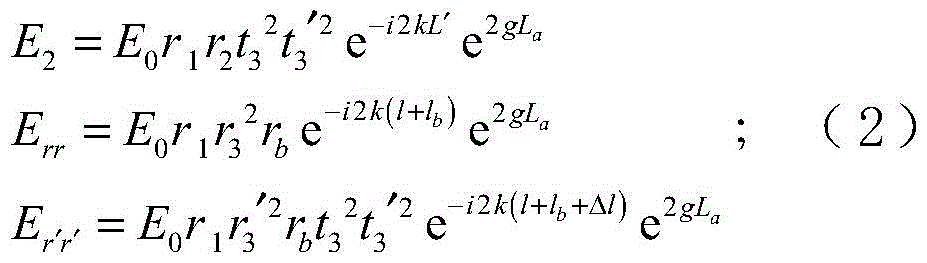
其中,g为激活介质的增益系数,la为激活介质(He-Ne激光毛细增益管) 有效长度,gla为激光在谐振腔内经过增益管一次获得的单程增益,L'为激光谐振腔的等效物理腔长度,k为波矢:k=2π/λ。Among them, g is the gain coefficient of the active medium, la is the effective length of the active medium (He-Ne laser capillary gain tube ), gl a is the one-way gain obtained by the laser passing through the gain tube once in the resonator, and L' is the laser resonator The equivalent physical cavity length of , k is the wave vector: k=2π/λ.
在计算激光谐振腔的等效物理腔长度的过程中,考虑激光增益介质和增透窗片3、光学玻璃片5的折射率,得:In the process of calculating the equivalent physical cavity length of the laser resonator, considering the refractive index of the laser gain medium, the

则根据自洽条件,从固定腔镜2出发的光场在腔内往返一周,回到固定腔镜2后应与初始状态保持一致,则有:Then according to the self-consistent condition, the light field from the fixed
E0=E2+Err+Er'r';E 0 =E 2 +E rr +E r'r' ;
即:which is:

同时,对于表面镀增透膜的光学玻璃片7,其反射率远小于1,而透射率近似等于1。对式(3)化简并舍去高阶小量,可以得到激光增益的表达式为:At the same time, for the

其中:in:

l1=l+lb-L',l2=l+lb+Δl-L'。l 1 =l+l b -L', l 2 =l+l b +Δl-L'.
当分叉腔长lb改变,激光光强产生周期为λ2的正弦调制,即当平面反射镜7由致动器驱动,每产生λ2位移,激光光强变化一个周期(回馈条纹),则致动器的总位移量ΔL(线性伸长量)为:When the length l b of the bifurcated cavity changes, the laser light intensity produces sinusoidal modulation with a period of λ2, that is, when the
ΔL=λ/2(M+m); (5)ΔL=λ/2(M+m); (5)
其中,M为回馈条纹整数部分,m为根据光强变化相位得到的回馈条纹小数部分。可通过数据处理单元9获得,参考检测获得的光波图像,整周期数即为M,不到一个周期的部分,按相位折算成小数部分m。Among them, M is the integer part of the feedback stripes, and m is the fractional part of the feedback stripes obtained according to the phase of the light intensity change. It can be obtained by the data processing unit 9, and the light wave image obtained by reference to the detection, the whole cycle number is M, and the part less than one cycle is converted into a fractional part m according to the phase.
对致动器6施加电压后其端面上各点的伸长量不一致,使平面反射镜7相对于面法线有很小的偏摆角
l1′=l+(1-ε/2)lb-ΔL-L′,l2′=l+(1+ε/2)lb-ΔL+Δl-L′; (6)l 1 '=l+(1-ε/2)l b -ΔL-L',l 2 '=l+(1+ε/2)l b -ΔL+Δl-L'; (6)
将式(6)代入式(4),可以计算致动器6位移过程中形成的激光光强变化曲线如图5所示。Substituting Equation (6) into Equation (4), the change curve of the laser light intensity formed during the displacement process of the
可以看出,随着致动器6发生位移,分叉腔长lb改变,在周期为λ2 的光强波动曲线上出现了长周期包络。则致动器6分平均位移可以根据光强波动周期,代入式(5)得到。而致动器6伸长过程中的偏摆角大小根据光强曲线中一个长周期包络下的半波长波动周期数N进行计算:It can be seen that with the displacement of the

由此,可以同时得到致动器6的线性伸长ΔL和沿x轴方向的偏摆角
在第一个角度计算获得第一组致动器的倾角数据;Calculate the inclination data of the first group of actuators at the first angle;
将致动器旋转90度,重复致动器倾角的计算步骤;Rotate the actuator by 90 degrees and repeat the steps of calculating the inclination of the actuator;
在第二个角度计算获得第二组致动器的倾角数据;Calculate the inclination angle data of the second group of actuators at the second angle;
结合第一组倾角数据和第二组倾角数据,获得致动器位移过程中实际倾角和倾斜方向。Combining the first set of inclination angle data and the second set of inclination angle data, the actual inclination angle and the inclination direction during the displacement process of the actuator are obtained.
例如,可将致动器6相对激光轴线转动90°,继续上面的测试,可以得到沿y轴方向的俯仰角ζ。综合两个倾角
以上所述,仅是本发明的较佳实施例而已,并非是对本发明作其它形式的限制,任何熟悉本专业的技术人员可能利用上述揭示的技术内容加以变更或改型为等同变化的等效实施例应用于其它领域,但是凡是未脱离本发明技术方案内容,依据本发明的技术实质对以上实施例所作的任何简单修改、等同变化与改型,仍属于本发明技术方案的保护范围。The above are only preferred embodiments of the present invention, and are not intended to limit the present invention in other forms. Any person skilled in the art may use the technical content disclosed above to make changes or modifications to equivalent changes. The embodiments are applied to other fields, but any simple modifications, equivalent changes and modifications made to the above embodiments according to the technical essence of the present invention still belong to the protection scope of the technical solutions of the present invention without departing from the content of the technical solutions of the present invention.
Claims (4)


Priority Applications (1)
| Application Number | Priority Date | Filing Date | Title |
|---|---|---|---|
| CN202110882268.2A CN113607062B (en) | 2021-08-02 | 2021-08-02 | Micro-actuator displacement and inclination angle measuring device and method |
Applications Claiming Priority (1)
| Application Number | Priority Date | Filing Date | Title |
|---|---|---|---|
| CN202110882268.2A CN113607062B (en) | 2021-08-02 | 2021-08-02 | Micro-actuator displacement and inclination angle measuring device and method |
Publications (2)
| Publication Number | Publication Date |
|---|---|
| CN113607062A CN113607062A (en) | 2021-11-05 |
| CN113607062B true CN113607062B (en) | 2022-08-09 |
Family
ID=78306494
Family Applications (1)
| Application Number | Title | Priority Date | Filing Date |
|---|---|---|---|
| CN202110882268.2A Active CN113607062B (en) | 2021-08-02 | 2021-08-02 | Micro-actuator displacement and inclination angle measuring device and method |
Country Status (1)
| Country | Link |
|---|---|
| CN (1) | CN113607062B (en) |
Families Citing this family (4)
| Publication number | Priority date | Publication date | Assignee | Title |
|---|---|---|---|---|
| CN115117723B (en) * | 2022-06-24 | 2025-04-08 | 中国科学院光电技术研究所 | Cavity adjusting method based on cavity mirror facula morphology monitoring |
| CN115325943B (en) * | 2022-08-18 | 2025-05-13 | 山东大学 | High-resolution displacement measuring device and measuring method |
| CN120294945B (en) * | 2025-04-11 | 2025-11-28 | 中山大学 | High-precision small-angle generating device and method based on optical path folding and amplifying |
| CN120176980B (en) * | 2025-05-21 | 2025-07-22 | 中国空气动力研究与发展中心超高速空气动力研究所 | A method and device for measuring sideslip angle of wind tunnel test model |
Family Cites Families (11)
| Publication number | Priority date | Publication date | Assignee | Title |
|---|---|---|---|---|
| DE10045535A1 (en) * | 2000-09-13 | 2002-04-04 | Gerhard Bonnet | Optical device |
| CN1333230C (en) * | 2005-01-26 | 2007-08-22 | 清华大学 | Laser feedback nano displaycement measuring device |
| JP2006322820A (en) * | 2005-05-19 | 2006-11-30 | Fdk Corp | Method and apparatus for measuring displacement of actuator |
| CN100412502C (en) * | 2006-07-20 | 2008-08-20 | 清华大学 | Beam Expanded Strong Light Folding Feedback Displacement Measurement System |
| CN100434862C (en) * | 2006-11-21 | 2008-11-19 | 暨南大学 | Micro-angle measurement method and device based on laser self-mixing interference |
| CN100538397C (en) * | 2007-03-16 | 2009-09-09 | 清华大学 | Double-refraction external cavity displacement measuring system |
| CN101261322B (en) * | 2008-04-18 | 2011-01-26 | 清华大学 | Double frequency He-Ne laser optical feedback distance measuring apparatus |
| CN102506715B (en) * | 2011-10-13 | 2013-12-11 | 清华大学 | Displacement data processing method based on microchip laser feedback interferometer |
| CN103471527B (en) * | 2013-08-14 | 2016-04-13 | 北京镭测科技有限公司 | A kind of laser external cavity feedback low-angle rolling angle measurement system |
| CN103633558B (en) * | 2013-12-20 | 2016-04-20 | 武汉光迅科技股份有限公司 | Adopt the wideband adjustable outside cavity gas laser of small-sized MEMS mirror |
| CN109813227B (en) * | 2017-11-20 | 2021-01-05 | 中国人民解放军第四军医大学 | Laser cavity tuning-based multiple feedback displacement measuring device and measuring method |
-
2021
- 2021-08-02 CN CN202110882268.2A patent/CN113607062B/en active Active
Also Published As
| Publication number | Publication date |
|---|---|
| CN113607062A (en) | 2021-11-05 |
Similar Documents
| Publication | Publication Date | Title |
|---|---|---|
| CN113607062B (en) | Micro-actuator displacement and inclination angle measuring device and method | |
| WO2000023764A1 (en) | Interferometer for optical wavelength monitoring | |
| CN119268602B (en) | Ultrahigh-precision small-angle measurement method and instrument for common-mode noise elimination double-laser frequency measurement | |
| JPH0379642B2 (en) | ||
| CN104697440A (en) | Multi-light-beam cascading staircase angle reflector laser interferometer and measurement method thereof | |
| CN102735430A (en) | Phase delay detection method and detection device | |
| CN1333230C (en) | Laser feedback nano displaycement measuring device | |
| CN110806274A (en) | Strain sensing measurement device and method based on multi-longitudinal mode self-mixing effect | |
| CN105509636B (en) | Measuring method of laser interferometer adopting wavelength correction type multi-beam-angle step reflector | |
| CN105371755B (en) | Laser wavelength correction method adopting wavelength correction type multi-beam step plane mirror laser interferometer | |
| CN105371754B (en) | A kind of measuring method that ladder corner reflector laser interferometer is cascaded using wavelength amendment type multiple beam | |
| CN119268601B (en) | Small-angle measurement reference device based on interferometric frequency selection and microprism array feedback | |
| US20100238456A1 (en) | Interferometer | |
| CN114963995B (en) | Michelson laser, implementation method thereof and displacement measurement method | |
| CN205619875U (en) | A wavelength-corrected multi-beam stepped mirror laser interferometer | |
| CN120488938A (en) | High-precision vortex grating interference displacement sensor and working method thereof | |
| JP4081317B2 (en) | Wavelength calibration interferometer | |
| CN117685875A (en) | A laser interferometer and its use method | |
| US7460243B2 (en) | Measuring apparatus sensitive to rotational but not translational or vibrational movement | |
| CN205245987U (en) | A wavelength-corrected multi-beam stepped mirror laser interferometer | |
| CN108832481A (en) | A kind of external cavity laser and its tuning method | |
| CN208171190U (en) | A kind of consistent formula displacement sensor of optical path | |
| WO2014146477A1 (en) | Wide range wavelength tunable etalon | |
| CN105371753B (en) | A laser wavelength correction method using wavelength correction multi-beam angle step mirror laser interferometer | |
| RU2060455C1 (en) | Device measuring linear translations |
Legal Events
| Date | Code | Title | Description |
|---|---|---|---|
| PB01 | Publication | ||
| PB01 | Publication | ||
| SE01 | Entry into force of request for substantive examination | ||
| SE01 | Entry into force of request for substantive examination | ||
| GR01 | Patent grant | ||
| GR01 | Patent grant |