Disclosure of Invention
The invention solves the problems: the method and the system for measuring the small angle of the light overcome the defects of the prior art, and have the advantages of high angle measurement resolution and simple measurement.
The principle of the invention is as follows: by utilizing the telescopic system, the conical lens, the image acquisition system and the image processing system, incident light rays are amplified by the telescopic system and then enter the large-end face of the conical lens through the diaphragm, total reflection is realized on the side face of the conical lens, the total reflection incidence angle is gradually reduced along with the increase of the total reflection times, and finally the incident light rays are emitted from the side wall of the conical lens to form a light spot image which changes monotonously and regularly, and the characteristic information of the light spot image is processed by adopting the same image processing method in the whole small-angle measurement range, namely, the corresponding light ray incidence angle is obtained through calculation.
In order to achieve the purpose, the invention adopts the following technical scheme:
one of the technical solutions of the invention is as follows: a small-angle incident light enters from a telescopic system, realizes angle amplification after passing through the telescopic system, then enters the large end face of a conical lens to reach a side wall, is emitted out of the side wall of the conical lens through a plurality of times of total reflection to form a light spot image with characteristic information changing regularly, and the light spot image is subjected to image processing to obtain a light incident angle; the characteristic information comprises the direction of the symmetry axis, the position of the center of mass, the area and the moment of inertia of the light spot image. As shown in fig. 4, the small angle interval of the incident light is
Wherein
Denotes the half cone angle of the axicon, n is the refractive index of the axicon material, and β is the magnification of the telescopic system. The angle interval of the light which is amplified by the angle of the telescopic system and then enters the big end face of the conical lens is
Wherein
Representing the half cone angle of the axicon, and n is the refractive index of the axicon material.
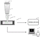
The light small angle measuring system for realizing the method comprises the following steps: the system comprises a telescope system, a diaphragm, a cone lens, an image acquisition system and an image processing system.
Incident light enters from the telescopic system, passes through the telescopic system, enters the large end face of the conical lens through the diaphragm, reaches the side wall, exits from the side wall of the conical lens to the image acquisition system, forms light spot images with characteristic information changing regularly, is displayed on the image display system, and can obtain the light incident angle after the light spot images are processed by the image processing system.
The telescope system adopts Galileo or Kepler telescope system, is arranged at the front end of the diaphragm and is coaxial with the diaphragm, and the front end of the diaphragm is provided with a lens
Is amplified to
The light with larger angle is incident to the cone lens, and the slight angle change of the incident light forms obvious angle change after passing through the telescopic system, thereby bringing obvious change of the light spot image characteristics and playing the roles of concentrating energy and improving precision;
the diaphragm is a circular through hole, has the size smaller than or equal to the caliber of the large end of the conical lens, is arranged on the surface of the large end of the conical lens and is coaxially arranged with the conical lens;
the parameters of the cone lens comprise a large-end aperture, a cone length, a cone angle, a material refractive index and the like, the cone lens with different parameters can form light spot images with different characteristic information, the light spot images are arranged at the rear end of the diaphragm and are coaxially arranged with the diaphragm, the end face of the large end of the cone lens is arranged in parallel with the receiving surface of the image acquisition system, the tip end of the cone lens is close to the receiving surface of the image acquisition system, incident light is totally reflected in the cone lens, the times of total reflection of the incident light at different angles are different, the incident light is emitted to the image acquisition system from different positions of the side wall of the cone lens after the total reflection condition is not met to form different light spot images, the light spot images formed by the incident light passing through the telescope system, the diaphragm and the cone lens can be completely received by the receiving surface of the single image acquisition system, and the characteristic information of the light spot images is regularly changed;
the image acquisition system has a complete receiving surface, does not lose image information, and can completely receive different light spot images formed by incident rays with different angles after passing through the telescopic system, the diaphragm and the conical lens;
the image processing system processes different light spot images of the image acquisition system, and calculates corresponding different light ray incidence angles according to characteristic information in the different light spot images;
the image display system displays the received light spot image;
and the image display system is used for displaying the received light spot image.
The characteristic information with regular change comprises the direction of a symmetry axis, the area, the position of a mass center, the moment of inertia and the like.
Fig. 2 is a diagram showing the ray trajectories of rays propagating in the meridional and non-meridional planes of the axicon lens. In the meridian plane of the axicon, for example, the propagation path of the
ray 1, the relationship between the height of the ray impinging on the image acquisition system and the incident angle is expressed as
Wherein L represents the conic length of the conic lens, k represents the kth total reflection, alpha
kIs the angle theta between the incident ray and the normal direction of the wall of the axicon
0Denotes the half-field angle of the axicon, α denotes the angle of incidence of the light rays, and n is the refractive index of the axicon material. Different from the light path track in the meridian plane, the light path track of the incident light in the non-meridian plane is generally a spatial spiral broken line, the broken line can be left-handed or right-handed, when the incident angle of the light is greater than a certain value, the light can be refracted to a position far away from the center in the non-meridian plane of the cone lens by the light, such as the propagation track of the
light 2, at the moment, the light spot image is necessarily split, the split image is overlarge, the image acquisition system in the prior art is difficult to completely receive, the image after the light spot splitting is not changed in a linear rule manner, other characteristic information needs to be extracted, meanwhile, an image processing method needs to be changed, and finally, the situation that the measurement accuracy of different incident light angles is inconsistent is necessarily caused, so that the split image is not advisable, but the invention only aims at small-angle measurement, the change of the light spot image of the small-angle incident light is changed in a rule, and the area of the light spot is moderate.
Furthermore, the light spot information received by the image acquisition system is processed by an image processing method, and is compared or interpolated with the calibration data, so that the light ray incidence angle can be obtained.
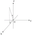
Further, a light spot image with symmetry and regular change is received through an image acquisition system, and the alpha angle of the light ray in the figure 3 is determined by image characteristics such as the position and the area of a mass center; the direction of the axis of symmetry of the image determines the azimuth angle beta of the rays in fig. 3.
Compared with the prior art, the invention has the advantages that:
(1) the invention aims at the incident ray angle
Small angle light of (2), the obtained facula patternThe image characteristic information changes monotonously and regularly, so that the incident angle can be calculated by processing the light spot image characteristic information by the same image processing method in the whole small-angle measurement range, the measurement angle does not need to be processed in a segmented manner, and light spots formed in the whole small-angle measurement range can be completely received by a receiving surface of a single image acquisition system. The invention has the advantages of high angle measurement resolution, simple measurement method and the like.
(2) The telescope system and the cone lens have the angle amplification effect, and the real-time light incident angle can be obtained by solving through the characteristic information of different light spot images, such as the direction of a symmetry axis, the position of a mass center, the area and the like. Compared with a method of directly adopting a cone lens, the method has the advantages that the angle change is more severe through the angle amplification of a telescopic system, and a more obvious and regularly changed light spot image is obtained through the cone lens, so that the measurement accuracy of the small-angle change of the light can be further improved; and the entrance pupil of the telescope system replaces the diaphragm in the prior patent publication No. CN111256649A, the luminous flux of the system is increased, and the signal-to-noise ratio of the image acquisition system is further improved.
Detailed Description
The embodiment of the invention provides a method and a system for measuring a small angle of light. The system comprises a telescope system, a diaphragm, a cone lens, an image acquisition system and an image processing system, wherein incident light rays are amplified by the telescope system and then enter the large end face of the cone lens through the diaphragm to reach the side wall for total reflection, and then are emitted from the side wall of the cone lens to form a light spot image, and after characteristic information of the light spot image is processed by the image processing system, the corresponding light ray incident angle can be calculated. The following detailed description, by way of example, refers to the accompanying drawings.
Examples
As shown in fig. 1-2, a system for measuring small angles of light according to the present invention comprises: a telescope system 2, a diaphragm 3, a cone lens 4, an image acquisition system 5, an image processing system 6 and an image display system 7. An incident light ray 1 is incident on an optical system from a telescopic system front port path, wherein:
parameters such as the magnification and the size of the telescopic system 2 need to be determined according to the parameters of the cone lens 4 and the image acquisition system 5. The too large magnification ratio can cause the over concentration of the light beam energy, and the formed light spot image is too small, thereby affecting the resolution ratio; if the magnification is too small, the angle amplification effect cannot be achieved, and the energy of the light beam is relatively dispersed.
During specific implementation, the telescope can be designed according to system requirements, ready-made telescope modules can be purchased, and the lenses and the axicons 4 can be coaxially arranged during installation. In this embodiment, a galilean telescope system with a magnification of 5.3 times and a clear aperture size of 11mm is adopted, light rays with an incident angle of 0 to 3 degrees are amplified by the telescope system to be emergent light rays with an incident angle of 0 to 15.9 degrees, and small angle changes of the incident light rays form obvious angle changes after passing through the telescope system, so that obvious changes of light spot image characteristics are brought, and the measurement accuracy of light ray angles is improved.
The diaphragm 3 is circular in shape, and the installation parameters may include its distance from the axicon 4, and the like.
In specific implementation, the diaphragm can be placed close to the large-end face of the cone lens 4, and the size of the diaphragm is smaller than or equal to the caliber of the large end of the cone lens.
The parameters of the large end aperture, the cone length, the cone angle and the like of the cone lens 4 are determined according to the size parameters of the telescopic system 2. The installation parameters may include the distance between the telescopic system 2 and the axicon lens 4, the distance between the axicon lens 4 and the receiving surface of the image acquisition system 5, the angle between the end surface of the large end of the axicon lens 4 and the receiving surface of the image acquisition system 5, and the like.
In specific implementation, the telescopic system 2 and the conical lens 4 can be matched in size and are relatively close to each other, the tip of the conical lens 4 is placed close to the receiving surface of the image acquisition system 5, and the end surface of the large end of the conical lens 4 is parallel to the receiving surface of the image acquisition system 5. In the embodiment, the cone lens is made of H-ZBAF21, the caliber of the large end is 10mm, the cone angle is 28.1 degrees, the spot image formed by the incident light of 0-3 degrees passing through the telescopic system, the diaphragm and the cone lens can be completely received by the receiving surface of the single image acquisition system, and the characteristic information of the spot image is changed regularly.
The image acquisition system 5 is used for receiving a light spot image formed by the incident light after passing through the optical system.
In specific implementation, image acquisition systems such as a CCD or a CMOS can be selected according to system requirements.
The image processing system 6 is used for processing the light spot image feature information received by the image acquisition system 5, including the symmetry axis direction, the area, the centroid position and the like of the light spot image.
During specific implementation, the corresponding incident ray azimuth angle information can be calculated by extracting the symmetry axis direction of the light spot image, and the angle information of the incident ray can be calculated by multiple ways such as the area and the centroid position of the light spot image, so that the measurement precision of the incident ray angle is ensured.
As shown in fig. 3, a spot image with symmetry and regular change is received by an image acquisition system, a coordinate system is established with a point projected by the tip of a cone lens onto a receiving surface of the image acquisition system as an origin, and the angle of inclination angle α of the light in fig. 3 can be determined by image characteristics such as centroid position, area and the like; the direction of the image symmetry axis determines the azimuth angle β of the rays in fig. 3.
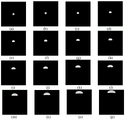
In this example, the magnification of the telescopic system used was 5.3 times, the material of the axicon lens was H-ZBAF21, the aperture of the large end was 10mm, and the cone angle was 28.1 °. The light spot image formed after the incident light telescopic system and the cone lens is shown in fig. 5, wherein: (a) a light incident angle of 0 °, (b) a light incident angle of 0.2 °, (c) a light incident angle of 0.4 °, (d) a light incident angle of 0.6 °, (e) a light incident angle of 0.8 °, (f) a light incident angle of 1 °, (g) a light incident angle of 1.2 °, (h) a light incident angle of 1.4 °, (i) a light incident angle of 1.6 °, (g) a light incident angle of 1.8 °, (k) a light incident angle of 2 °, (l) a light incident angle of 2.2 °, (m) a light incident angle of 2.4 °, (n) a light incident angle of 2.6 °, (o) a light incident angle of 2.8 °, (p) a light incident angle of 3 °, wherein a telescopic system magnification of 5.3 is used, a refractive index of the cone lens material of 1.72, a large end diameter of 10mm, and a cone angle of 28.1 °.
In the figure 5, the light spot image can be completely received by the receiving surface of the image acquisition system without image splicing and other processing, the loss of image information is avoided to a certain extent, the characteristic information of the light spot image comprises a centroid position, an area and the like which are regularly changed in the whole 0-3-degree light incidence angle range, the angle information of the incident light and the characteristic information of the light spot image are in one-to-one correspondence, a coordinate system is established by taking the point of the cone lens tip projected onto the receiving surface of the image acquisition system as an original point, the characteristic information of the light spot image comprises the direction of a symmetry axis, the centroid position, the area and the like, image processing is carried out by comparing or interpolating with calibration data, the angle information of the incident light can be obtained, and the calculation formula of the rotational inertia is used for obtaining the angle information of the incident light


Wherein (i)
0,j
0) The intersection point of the central axis of the conical lens and the imaging plane is represented, m and n represent the pixel size of the image, f (i, j) represents the gray value of the binarized image at the position, the incident angle is solved by adopting a method of moment of inertia, and the obtained measurement precision is improved by 32% compared with the precision of the prior patent publication No. CN 111256649A.
Finally, it should be noted that: the above examples are only for illustrating the technical solution of the present invention, and not for limiting the same. Those of ordinary skill in the art will understand that: modifications to the technical solutions described in the foregoing embodiments or equivalent replacements of some or all technical features may be made without departing from the scope of the technical solutions of the embodiments of the present invention.