Multi-function machine for cleaning and disinfecting surfaces and environments
Technical Field
The present invention relates to a multi-function machine for cleaning and disinfecting surfaces and environments, which can be generally used for cleaning and disinfecting operations by means of a single machine containing all the equipment necessary to carry out the operations.
Background
In the field of household and industrial use of machines for cleaning and disinfecting environments and surfaces, multi-function machines are known which comprise a series of devices, which are combined together in a single-body machine and enable the user to carry out a series of cleaning and disinfecting operations, using the various devices alone or in combination with one another.
Patent application WO2018146710 describes a multifunction machine for cleaning surfaces, in particular a multifunction vacuum cleaner comprising a main body machine inside which a passage is defined for the passage of a flow of air sucked in and of debris suspended in the flow of air sucked in.
The air and debris are bubbled in a tank containing a liquid, typically water, to release the entrained debris particles into it.
After passing through this tank, which is in fact a water filter, the air flow is conveyed through an internal path into the housing base of the vacuum cleaner motor, in order to be used for cooling it, and then finally is discharged outside the main body machine, into the surrounding environment.
In the multi-functional vacuum cleaner, a steam generating unit is also provided, which can be activated upon command (e.g. when the cleaning operation is particularly difficult in the presence of stubborn dirt).
The steam, together with the suction, acts to dissolve dirt which, after separation from the surface to be cleaned, is sucked in a conventional manner.
In such a multi-functional vacuum cleaner, there is also provided the installation of a device for diffusing perfume into the air as an accessory, so that the use environment of the vacuum cleaner is more comfortable.
A vacuum cleaner with an ionizer is known from the patent EP 1330976.
According to this patent, the vacuum cleaner comprises a suction channel of air and debris starting from a flexible suction duct connected to a motor unit driving a fan capable of generating a low air pressure for the suction action.
Upstream of the motor unit there is provided a debris collection chamber in which a paper bag is contained, the latter being collected therein.
The drawn-in air stream is then filtered by primary and secondary filters and then released back into the atmosphere.
The ionizer may be mounted directly on the suction nozzle with which the suction duct is equipped, or may be mounted immediately downstream of the motor unit, before the sucked air flow exits the main machine.
This prior art has some disadvantages.
One drawback associated with patent application WO2018146710 is that no means is provided for generating and emitting negative and positive ions in a multi-function vacuum cleaner.
This limits the performance of the multi-functional vacuum cleaner, particularly in terms of purification and deodorization of the sucked air.
A second drawback, particularly relevant to patent EP1330976, is that no liquid can be sucked in using such ion-generating vacuum cleaners.
In addition, in both cases, there is only one passage for the sucked air, and therefore, in the case of generating ions, the generation and discharge passage cannot be separated from the specific passage for sucking the debris.
For this reason, these known vacuum cleaners cannot be equipped with water filtration devices or are not suitable for sucking in dry debris and debris-laden liquids.
Furthermore, it sometimes happens that the ions generated and emitted in the same suction circuit of the known vacuum cleaners are partially or totally covered by debris sucked in with the air, thus significantly reducing their effectiveness in sterilizing the environment.
Object of the Invention
It is an object of the present invention to improve the prior art.
Another object of the present invention is to provide a machine for cleaning and disinfecting surfaces and environments which is capable of generating ions while also being capable of aspirating liquids without risking the safety of the user.
According to one aspect of the invention, there is provided a machine for cleaning and disinfecting surfaces and environments, according to the features of claim 1.
Further features of the invention are included in the dependent claims.
The invention can obtain the following advantages:
-obtaining a machine for cleaning and disinfecting surfaces and environments equipped with a number of functions that can be used both alone and in combination with each other;
-obtaining a machine for cleaning and disinfecting surfaces and environments, which is able to suck in solids, even liquids or debris immersed in liquids, generating positive or negative ions according to the needs;
there is no need to use bulk bags to collect debris and dirt sucked in by the multifunction machine capable of generating ions.
Drawings
Further characteristics and advantages of the invention will become better apparent from the detailed description of a preferred but not exclusive embodiment of a machine for cleaning and disinfecting surfaces and environments, described as a non-limiting embodiment in the accompanying drawings, wherein:
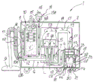
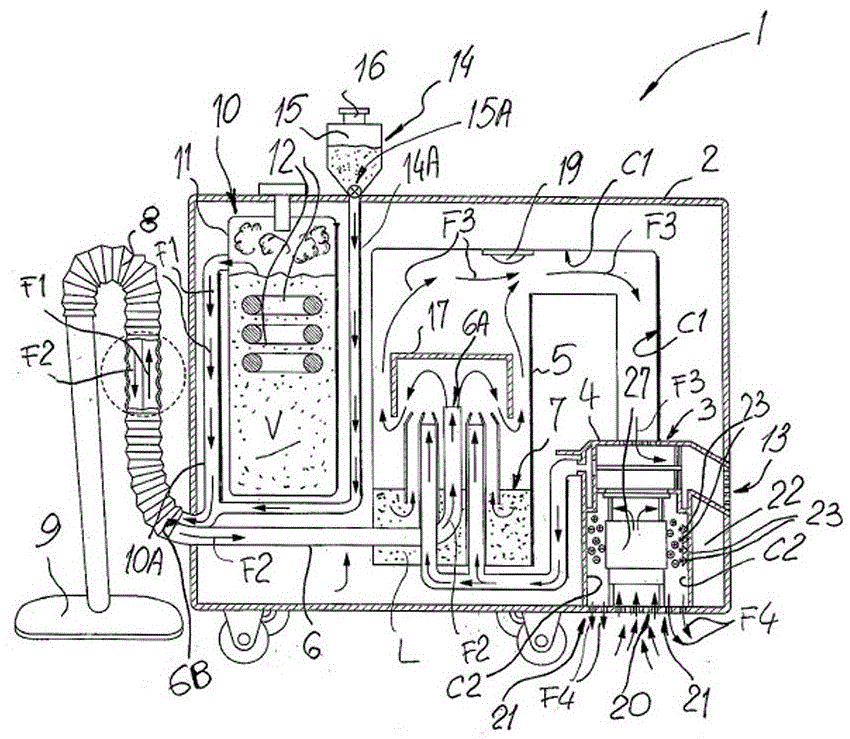
FIG. 1 is a very schematic cross-sectional view of a machine for cleaning and disinfecting surfaces and environments according to the present invention;
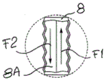
FIG. 2 is a detailed view of a portion of the machine of FIG. 1;
FIG. 3 is a detailed view, on a slightly enlarged scale, of a portion of an ion releasing element with which the machine according to the invention is equipped to clean and disinfect surfaces and environments;
figure 4 is another very schematic cross-sectional view of a second version of the machine for cleaning and disinfecting surfaces and environments according to the present invention.
Detailed description of the preferred exemplary embodiments
With reference to fig. 1, 1 shows a machine for cleaning and disinfecting surfaces and environments according to the invention, and is hereinafter simply referred to as machine 1.
The machine 1 is preferably, but not exclusively, made in the form of a vacuum cleaner household appliance and has a box-like main body machine 2 inside which a plurality of devices are assembled to perform a corresponding number of operating functions.
In detail, the machine 1 comprises a suction group (group), generally an electric motor 3, which is housed inside a containment casing 4 and is connected to a tank 5 of liquid L by a primary circuit C1.
The tank 5 is only partially filled with liquid L up to the level 7 and it is an embodiment of both a wet filtering device and a device for collecting sucked up debris.
An end portion 6A of the duct 6 flows into the upper portion of said tank 5, which defines one end of said duct 6, while its opposite end portion 6B is provided with a mouth (mouth) for engaging a conventional flexible pipe 8 provided with the machine 1 and connecting the opposite end portion 6B to a terminal mouth 9.
Inside the main body machine 2 there is also placed a unit, indicated as a whole with 10, for generating steam and discharging it on command towards the surfaces and the environment to be cleaned and disinfected.
Said unit 10 comprises a second tank 11 in which there is arranged an electric resistance 12 which can be heated, the whole usually forming a boiler, and a volume V of water to generate steam when required during use of the machine 1.
The steam generated is conveyed towards the mouth 9 in the direction of the arrow F1 through a separate duct 10A, this duct 10A extending inside the flexible tube 8 and parallel thereto, but separated from the duct 8A, the suction air (arrow F2) and the suction debris suspended therein flowing from the outside to the inside of the main body machine 2 through the duct 8A.
The tank 5 and the casing 4 are connected to each other by a primary circuit C1 in which the sucked air circulates (arrow F3) after being purified from the debris that exits from the end 6A, being released into the liquid L contained in the tank 10.
Said primary circuit C1 has a first inlet consisting of the same end 6B of the duct 6 and an outlet 13 made in the main body machine 2 for discharging air to the outside.
A further tube 14A is also collected in the tube 8, which is connected to a device 14 for accumulating and emitting a perfume, fragrance or disinfectant, preferably prepared in atomized or gaseous form, which is loaded into a further third tank 15 with which the device 14 is equipped, and which is equipped with a loading orifice 16 and is connected to the main body machine 2.
The further tube 14A is controlled by a valve 15A having two alternative positions of use, precisely open or closed.
Inside the tank 5 there are also mounted deflection means 17 and a source 19 of emission of UV or UV-C rays.
Also defined in the main machine 2 is a secondary circuit C2 of air having a second inlet 20 and a second outlet 21 and inside which flows an air flow F4 drawn in by a fan 27 driven in rotation by the same motor 3, but of a size significantly smaller than the latter, so as to generate a depression of absolute value lower than that generated by the motor 3 in the primary circuit C1.
The ionization device 22 is mounted in a secondary circuit C2, the structure of which is known to the person skilled in the art, which comprises a plurality of elements 23 for delivering positive and negative ions, and which can be activated by a user by command.
Referring to fig. 4, in which elements identical to those of fig. 1 have been designated by the same reference numerals for the sake of convenience, it is noted that inside the main body machine 2 there are again provided: motor 3, placed inside its own containment casing 4, tank 5, in which liquid L accumulates until reaching level 7, secondary circuit C2, in which a depression is obtained during operation of machine 1 by the action of fan 27 driven by motor 3, ionization device 22 and corresponding ion transport element 23.
In this second version of the machine 1, there is also still provided a conduit 6, to the end 6B of which there is connected a flexible tube 8 and its terminal mouth 9.
The steam generating unit 10 is also incorporated in the main body machine 2, while, in contrast to the previous versions, an assembly of molecular separator devices 28 is provided inside the tank 5, which is intended to further filter the air flow F3 discharged from the liquid L, eliminating therefrom the very small-sized particles that may remain in suspension even after bubbling in the liquid L.
The molecular separator device 28 comprises a rotating fan 29, which is arranged inside the supporting shell, can be equipped with a sponge-like peripheral filter, and is driven by the low air pressure generated by the motor 3 inside the tank 5 through the primary circuit C1.
The rotating fan 29 has a plurality of passage holes 30 through which the air flow F3 passes after releasing the debris sucked into the liquid L by gravity or by the impact on the rotating fan 29 itself.
Thus, when in the tank 5, the molecular separator 28 dynamically separates the residual debris from the sucked-in air flow F3, in effect acting as a filter, so that the filtered air flow F3, after passing through said holes 30, can first reach the inside of the casing 4 and flap (lap) the motor 3, cooling it, and then be discharged completely purified to the outside environment through said first outlet 13.
With reference to fig. 3, it can be noted in detail that each element 23 comprises a thin electric conduit 24 for connection to the ionization device 22, which ends with an expanded end 25 and which preferably, but not exclusively, has a truncated-cone or brush-like shape, made up of a bundle of thin bristles, preferably made of carbon fibers, which, when they are tapped by an air flow F4, release the ions into the environment.
It should be noted that the primary circuit C1 and the secondary circuit C2 are manufactured in a manner always separated from each other, since the ionization device 22 placed along the secondary circuit C2 must not have any contact points with the liquid L for functional safety and user safety.
The operation of the multi-function machine for cleaning and disinfecting surfaces and environments is described below.
In the first embodiment of the multifunction machine 1 shown in fig. 1, when only a suction action is required, the user activates the motor 3 which provides to put the tank 5 in depression and to generate a suction action which is transmitted to the outside through said flexible duct 8 which conveys all the suction debris suspended in the suction air flow F2 inside said tank 5.
The sucked air flow F2 exits from the end 6A of the conduit 6 and bubbles in the liquid L below the water line 7, releasing therein most of the sucked debris, typically those of greater weight, which collects at the bottom of the tank 5.
The air flow F3, purified from the most coarse debris, is directed by the Venturi (Venturi) effect towards the deflector 17, which creates turbulence in the portion of the tank 5 not occupied by the liquid L, so that the debris particles, which may still remain in suspension, fall back to the latter again.
The deflector 17 deflects the air flow F3 towards the motor 3 through the primary circuit C1 so that they can cool, flap and then be discharged outwards through the first outlet 13.
During operation of the machine 1, a user, facing particularly tough soils on the surface to be cleaned and disinfected, can activate the unit 10 for generating steam which passes through the inside of the flexible tube 8 through the independent duct 10A until it is expelled from the terminal mouth 9 towards the surface.
Also during operation of the machine 1, the user can also activate the ionization device 22, which generates positive or negative ions, which are introduced into the surrounding environment, enter the secondary circuit C2 and exit from the second outlet 21, without beating in any way the liquid L contained in the tank 5, thus being in maximum safety conditions.
Also during operation of the machine 1, when required, the user can open the valve 15A and expel the deodorant or disinfectant substance from the terminal mouth 9 together with the steam generated by the steam generating unit 10.
The function of the second version of the machine 1 shown in fig. 4 is substantially the same as that described in the first version, the only difference being that the air flow F3 leaving the liquid L is sucked towards the holes 30 of the molecular separator 28, which, by rotating, reduces from the air flow F3 the residual debris that may still be suspended therein due to its very small size and weight.
It should be noted that in both versions of machine 1, during the passage between the level 7 of liquid L and the deflector 17 or molecular separator 28, the air flow F3 is subjected to the antibacterial sterilizing action provided by the source 19 of UV or UV-C rays, preferably arranged on top of tank 5.
Finally, the multifunction machine according to the invention is capable of generating and emitting ions only through the secondary circuit C2, while the primary circuit C1 is used for suctioning debris and dirt dried and contained in the suctioned liquid.
In practice it has proved that the invention achieves the intended aim, namely to combine a plurality of devices in a single multifunctional machine, each of which provides specific properties.
Those skilled in the art will appreciate that the devices incorporated in the multifunctional machine 1 can be driven either independently of each other, simultaneously, or even only partially.
The inventive concept is susceptible to modifications and variations, all of which are within the scope of the inventive concept.
Moreover, all the details may be replaced with other technically equivalent elements.
In their actual implementation, any other materials may be used as required, as well as other shapes and dimensions, without departing from the main field of protection defined by the following claims.