CN113734026B - Rescue vehicle for inflammable and explosive gas of dangerous chemicals - Google Patents
Rescue vehicle for inflammable and explosive gas of dangerous chemicals Download PDFInfo
- Publication number
- CN113734026B CN113734026B CN202111026615.8A CN202111026615A CN113734026B CN 113734026 B CN113734026 B CN 113734026B CN 202111026615 A CN202111026615 A CN 202111026615A CN 113734026 B CN113734026 B CN 113734026B
- Authority
- CN
- China
- Prior art keywords
- furnace body
- cover
- communicated
- air
- pipe
- Prior art date
- Legal status (The legal status is an assumption and is not a legal conclusion. Google has not performed a legal analysis and makes no representation as to the accuracy of the status listed.)
- Active
Links
- 239000002360 explosive Substances 0.000 title claims abstract description 45
- 239000000126 substance Substances 0.000 title claims abstract description 14
- XLYOFNOQVPJJNP-UHFFFAOYSA-N water Substances O XLYOFNOQVPJJNP-UHFFFAOYSA-N 0.000 claims abstract description 100
- 238000002485 combustion reaction Methods 0.000 claims abstract description 52
- 239000007788 liquid Substances 0.000 claims abstract description 33
- 230000001681 protective effect Effects 0.000 claims abstract description 9
- 239000007789 gas Substances 0.000 claims description 47
- 239000007921 spray Substances 0.000 claims description 20
- 239000000428 dust Substances 0.000 claims description 15
- 239000002184 metal Substances 0.000 claims description 11
- 230000005012 migration Effects 0.000 claims description 10
- 238000013508 migration Methods 0.000 claims description 10
- 230000005611 electricity Effects 0.000 claims description 9
- 230000003068 static effect Effects 0.000 claims description 9
- 238000002347 injection Methods 0.000 claims description 6
- 239000007924 injection Substances 0.000 claims description 6
- 238000002156 mixing Methods 0.000 claims description 4
- 230000007306 turnover Effects 0.000 claims description 4
- 230000009471 action Effects 0.000 claims description 3
- 239000000383 hazardous chemical Substances 0.000 claims 6
- 238000004378 air conditioning Methods 0.000 abstract 1
- 238000005192 partition Methods 0.000 description 12
- 238000005507 spraying Methods 0.000 description 8
- 238000010586 diagram Methods 0.000 description 3
- 238000000034 method Methods 0.000 description 3
- 230000008569 process Effects 0.000 description 3
- 239000000243 solution Substances 0.000 description 2
- 206010039203 Road traffic accident Diseases 0.000 description 1
- 208000027418 Wounds and injury Diseases 0.000 description 1
- 238000000889 atomisation Methods 0.000 description 1
- 230000006378 damage Effects 0.000 description 1
- 238000004200 deflagration Methods 0.000 description 1
- 238000005516 engineering process Methods 0.000 description 1
- 238000004880 explosion Methods 0.000 description 1
- 208000014674 injury Diseases 0.000 description 1
- 238000002955 isolation Methods 0.000 description 1
- 239000003595 mist Substances 0.000 description 1
- 230000002035 prolonged effect Effects 0.000 description 1
- 230000009897 systematic effect Effects 0.000 description 1
- 238000009423 ventilation Methods 0.000 description 1
Images




Classifications
-
- B—PERFORMING OPERATIONS; TRANSPORTING
- B60—VEHICLES IN GENERAL
- B60P—VEHICLES ADAPTED FOR LOAD TRANSPORTATION OR TO TRANSPORT, TO CARRY, OR TO COMPRISE SPECIAL LOADS OR OBJECTS
- B60P3/00—Vehicles adapted to transport, to carry or to comprise special loads or objects
-
- B—PERFORMING OPERATIONS; TRANSPORTING
- B60—VEHICLES IN GENERAL
- B60P—VEHICLES ADAPTED FOR LOAD TRANSPORTATION OR TO TRANSPORT, TO CARRY, OR TO COMPRISE SPECIAL LOADS OR OBJECTS
- B60P3/00—Vehicles adapted to transport, to carry or to comprise special loads or objects
- B60P3/30—Spraying vehicles
Landscapes
- Engineering & Computer Science (AREA)
- Health & Medical Sciences (AREA)
- Public Health (AREA)
- Transportation (AREA)
- Mechanical Engineering (AREA)
- Aviation & Aerospace Engineering (AREA)
- General Health & Medical Sciences (AREA)
- Toxicology (AREA)
- Fire-Extinguishing By Fire Departments, And Fire-Extinguishing Equipment And Control Thereof (AREA)
Abstract
The invention discloses a rescue vehicle for flammable and explosive gas of dangerous chemicals, which comprises a vehicle body and a vehicle box body, and is characterized in that: the novel air-conditioning device is characterized in that a protective cover is arranged on the outer side of the top wall of the box body, a ventilator is arranged in the protective cover, a gas-liquid separator, a circulating water pump and a combustion furnace and a drainage fan are respectively arranged in the box body, a gas outlet of the gas-liquid separator is communicated with an air inlet of the ventilator, an air outlet of the ventilator is communicated with a three-way control valve, a first storage chamber, a second storage chamber and a third storage chamber are respectively arranged at the bottom of the box body and are respectively used for storing a drainage cover, a telescopic air pipe and a fire-fighting water pipe, the drainage cover is communicated with a mixed inlet of the gas-liquid separator through the telescopic air pipe, the three-way control valve is communicated with an air inlet of the drainage fan through the telescopic air pipe, and an air outlet of the drainage fan is communicated with the combustion furnace.
Description
Technical Field
The invention relates to the technical field of emergency disposal of dangerous chemicals, in particular to a rescue vehicle for flammable and explosive gases of dangerous chemicals.
Background
In case of traffic accidents in the transportation process of dangerous chemical transport vehicles, chemical corrosive liquid or inflammable and explosive gas in a storage tank is leaked, so that the surroundings of the accidents are in inflammable and explosive dangerous environments, trapped personnel on the rescue transport vehicles usually need to use mechanical tools for cutting and breaking, but in the cutting and breaking processes, sparks or static electricity are extremely easy to generate, and secondary accidents of burning and explosion are caused.
In addition, for plants for producing or storing flammable and explosive dangerous chemicals, due to sudden accidents, the flammable and explosive dangerous chemicals leak, so that the closed plants form dangerous flammable and explosive environments, and the ventilation conditions of the plants are relatively poor, the flammable and explosive gases are difficult to diffuse rapidly, and rescue cannot be carried out normally.
Aiming at similar accident rescue, the leakage part can only be plugged at present in general rescue, then the concentration of inflammable and explosive gas volatilized into the air at the accident site is waited to be reduced to be within a safety coefficient, and then the rescue to personnel is implemented by using a mechanical tool to break and tear, so that the best rescue time is very easy to miss for the trapped personnel with serious injury, and the trapped personnel are casualty.
In addition, since the accident site is relatively few in emergency rescue resources and there may be many places for leakage, a systematic rescue facility is required to evacuate the flammable and explosive gases generated at the accident site.
Disclosure of Invention
Aiming at the problem that the rescue cannot be carried out in time due to the fact that flammable and explosive gases are generated by flammable and explosive dangerous chemicals in the background technology, a series of potential safety hazards are induced, the invention provides a rescue vehicle for the flammable and explosive gases of the dangerous chemicals.
The invention adopts the following technical scheme to achieve the aim: the utility model provides a rescue car of dangerous chemicals inflammable and explosive gas, including the car body, and set up in car body is last, its characterized in that: the novel air conditioner is characterized in that a protective cover is arranged on the outer side of the top wall of the car box body, a ventilator is arranged in the protective cover, an operation box is arranged on the outer side of any side wall of the car box body, a gas-liquid separator is arranged in the car box body, two limit guide rails are further arranged on the inner side of the bottom wall of the car box body, a combustion furnace and a drainage fan are respectively arranged between the two limit guide rails, the combustion furnace and the drainage fan are both arranged between the two limit guide rails, a gas outlet of the gas-liquid separator is communicated with an air inlet of the ventilator through an air duct, an air outlet of the ventilator is communicated with a three-way control valve through the air duct, the three-way control valve is located in the car box body, a first storage chamber, a second storage chamber and a third storage chamber are respectively arranged at the bottom of the car box body, the first storage chamber, the second storage chamber and the third storage chamber are respectively used for storing a drainage cover, a telescopic air duct and a fire-fighting water pipe, the drainage cover is respectively communicated with a mixed inlet of the gas-liquid separator, the three-way control valve is connected with a plurality of telescopic air ducts through a plurality of interfaces, the three-way control valves are communicated with the air inlets of the telescopic air separator, and the ventilator is communicated with the air inlet of the operation box, and the three-way control valve is communicated with the air inlet through the air duct.
Preferably, a water storage tank and a circulating water pump are further installed in the carriage body, a water injection pipe is arranged at the top of the water storage tank, the water injection pipe extends upwards to the outside of the carriage body, a liquid outlet of the gas-liquid separator is connected with the circulating water pump through a pipeline and is communicated with the water storage tank, and the circulating water pump is connected to the control box.
Preferably, the drainage cover comprises a cover body, the cover body is wide-mouth funnel-shaped, the bottom of the drainage cover corresponds to an air outlet formed by communicating interfaces, handles and water receiving pipes are arranged on two opposite side walls of the cover body, a spray header is communicated with two water receiving pipes in the cover body, a plurality of atomizing spray heads are uniformly arranged on the spray header at equal intervals, the atomizing spray heads are all directed to the air outlet, the two water receiving pipes are respectively connected with an air outlet interface of a water storage tank, the plurality of air outlet interfaces are respectively arranged on the side wall of the lower end of the water storage tank, an air pump is also communicated with the water storage tank, the air pump is externally connected with the control box, and water in the water storage tank is in a high-pressure state.
Preferably, a door opening is formed in the right side wall of the carriage body, the door opening is used for storing and taking out the combustion furnace and the drainage fan, a door plate is hinged to the right side wall of the carriage body corresponding to the door opening, two hydraulic cylinders are arranged between the door plate and the carriage body, the door plate is powered by the two hydraulic cylinders to realize overturning action of the door plate, so that the door opening is opened or closed, a hydraulic system matched with the two hydraulic cylinders is further arranged on the carriage body, and the hydraulic system is connected to the control box.
Preferably, a suspending ladder frame is arranged on the outer side of the left side wall of the carriage body.
Preferably, the interface comprises a plug connector and a socket connector corresponding to the plug connector, the plug connector is connected with the socket connector by a buckle, a metal electrostatic belt is arranged on the plug connector or the socket connector, a conductive contact pin is arranged at the free end of the metal electrostatic belt, the conductive contact pin is inserted into the ground, and static electricity generated in the telescopic air pipe is introduced into the ground through the metal electrostatic belt, so that flammable and explosive gas in the migration channel is prevented from detonating due to the static electricity.
Preferably, the front side wall and the rear side wall of the carriage body are respectively connected with a first cover plate in a turnover manner, the two first cover plates are respectively positioned at the mixing inlet of the gas-liquid separator, and the two bottom side walls of the carriage body are respectively connected with a second cover plate, a third cover plate and a fourth cover plate in a turnover manner corresponding to the first storage chamber, the second storage chamber and the third storage chamber.
Preferably, the combustion furnace comprises an outer furnace body, the inside fixedly connected with of outer furnace body is interior furnace body, the bottom downwardly extending of interior furnace body to keep apart with the diapire of outer furnace body and form the air inlet chamber, the intercommunication has the air inlet pipe on the diapire of interior furnace body, the air inlet pipe passes through the fixed plate and installs on the diapire outside of interior furnace body, and with the air outlet of drainage fan passes through flexible tuber pipe is linked together, a plurality of first bar through-holes have evenly been seted up along radial on the outer furnace body diapire in the interior furnace body, a plurality of first round holes have been seted up to the circumference on the lateral wall of interior furnace body be provided with pulse igniter on the lateral wall outside of outer furnace body, pulse igniter loops through first pipe, second pipe connection ignition needle, first pipe passes the lateral wall of outer furnace body in proper order horizontally, the lateral wall of interior furnace body to with set up perpendicularly in the inside of interior furnace body is linked together, a plurality of ignition needles along the axial setting is on the lateral wall of second pipe, and radially symmetrically is provided with two rows, a plurality of bracing pieces are connected with through many covers on the lateral wall of outer bracing piece, the outer furnace body is covered on the outer side has the outer dust cover.
Preferably, the inside of interior furnace body is provided with first baffle, second baffle from bottom to top respectively, first baffle, second baffle all outwards extend to on the inner wall of outer furnace body, are located and encircle on the first baffle between outer furnace body and the interior furnace body and offer a plurality of second round holes, are located and evenly offer a plurality of second bar through-holes along radial on the second baffle in the interior furnace body, the inside first combustion chamber that forms of interior furnace body between the diapire of outer furnace body and the first baffle, the inside second combustion chamber that forms of interior furnace body between first baffle and the second baffle, the inside third combustion chamber that forms of interior furnace body between the roof of second baffle and outer furnace body, the diapire lower extreme center of outer furnace body is provided with the pivot seat, be provided with the pivot in the pivot seat, be provided with turbine blade in the pivot, turbine blade is located in the air inlet chamber.
Preferably, the dust fall cover is provided with a spraying device, the spraying device comprises an annular pipe arranged on the inner side of the dust fall cover, a plurality of spraying heads are uniformly arranged at the lower end of the annular pipe, the upper end of the annular pipe is communicated with a water inlet connecting pipe, and the water inlet connecting pipe is externally connected with a water outlet interface of the water storage tank through a fire-fighting water pipe.
Compared with the prior art, the invention has the following advantages: 1. according to the invention, negative pressure generated by the vehicle-mounted ventilator is utilized, the interface and the telescopic air pipe are respectively and rapidly communicated with the drainage cover and the combustion furnace to form a migration system of inflammable and explosive gas, the leaked gas at an accident point is migrated to a safe discharge point, and the combustion furnace is adopted for combustion and discharge of dangerous cases, in addition, the gas-liquid separator is provided with a plurality of air inlet interfaces and a three-way control valve connected by the ventilator, so that the problems of leakage and danger discharge at a plurality of places and large-flow inflammable and explosive gas shunting combustion operation can be effectively solved; 2. in order to prevent inflammable and explosive gas from being mixed with external sparks and entering a migration channel, an atomization nozzle is added in a drainage cover to form a water mist isolation wall, meanwhile, a metal electrostatic belt and conductive facilities of conductive pins are arranged on an interface, so that static electricity generated in the migration channel is introduced to the ground, and the hidden danger of deflagration caused by the external sparks or static electricity in a telescopic air pipe in the migration process of the inflammable and explosive gas is effectively solved; 3. according to the invention, the gas-liquid separator is arranged between the drainage cover and the ventilator, so that the water mixed with the inflammable and explosive gas entering the telescopic air pipe is separated, and the inflammable and explosive gas can be conveniently and rapidly transported in the migration channel; 4. according to the invention, the liquid outlet of the gas-liquid separator is communicated with the water storage tank through the circulating water pump to form a water circulation loop, so that the atomizing operation time is effectively prolonged; 5. according to the invention, the turbine blades are arranged in the air inlet chamber of the combustion furnace, so that inflammable and explosive gas enters the first combustion chamber in a vortex manner to be subjected to full-contact combustion, and is repeatedly combusted sequentially through the second combustion chamber and the third combustion chamber, so that inflammable and explosive gas components migrated from an accident point are thoroughly combusted, and hidden danger is fundamentally eliminated; 6. the spraying device is arranged in the dust hood, and the water curtain wall is formed by the spraying device, so that part of sparks after combustion are effectively isolated from escaping from the combustion furnace; 7. the invention adopts a vehicle-mounted integrated design, is convenient for quick movement, and is suitable for various large and medium rescue sites.
Drawings
FIG. 1 is a side view of the present invention;
FIG. 2 is a schematic perspective view of the present invention;
FIG. 3 is a schematic diagram of the structure of the present invention;
FIG. 4 is a schematic perspective view of a drainage cover according to the present invention;
FIG. 5 is a schematic view showing a cross-sectional structure of a drainage cover in the present invention;
FIG. 6 is a schematic diagram of an interface according to the present invention;
FIG. 7 is a schematic perspective view of a burner according to the present invention;
FIG. 8 is a schematic view of a burner according to the present invention;
FIG. 9 is a schematic view showing the connection of the internal structure of the burner according to the present invention;
FIG. 10 is a schematic diagram of the connection of a dust hood to a spray device in accordance with the present invention;
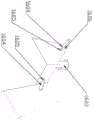
in the figure: the vehicle body 1, the vehicle body case 2, the first storage room 2a, the second storage room 2b, the third storage room 2c, the hanging ladder frame 3, the protective cover 4, the vehicle door panel 5, the hydraulic cylinder 6, the first cover plate 7, the operating box 8, the third cover plate 9, the second cover plate 10, the fourth cover plate 11, the water storage tank 12, the water outlet port 1201, the water injection pipe 13, the ventilator 14, the gas-liquid separator 15, the mixing inlet 1501, the liquid outlet 1502, the gas outlet 1503, the drainage cover 16, the cover body 1601, the lifting handle 1602, the gas outlet 1603, the water receiving pipe 1604, the atomizing nozzle 1605, the spray header 1606, the fire fighting water pipe 17, the circulating water pump 18, the three-way control valve 19, the combustion furnace 20, the outer furnace body 2001, the dust fall cover 2002, the support rod 2003, the inner furnace body 2004 the first partition 2005, the second partition 2006, the pivot mount 2007, the pillar leg 2008, the first bar-shaped through hole 2001a, the first round hole 2004a, the second round hole 2005a, the second bar-shaped through hole 2006a, the drainage fan 21, the interface 22, the plug connector 2201, the socket connector 2202, the metal electrostatic belt 23, the conductive pin 24, the telescopic air duct 25, the rail 26, the pulse igniter 27, the first duct 28, the second duct 29, the ignition needle 30, the air intake duct 31, the fixing plate 32, the turbine blade 33, the rotation shaft 34, the spray device 35, the annular pipe 3501, the spray header 3502, the water intake nozzle 3503, the air pump 36, the air intake chamber 001, the first combustion chamber 002, the second combustion chamber 003, and the third combustion chamber 004.
Detailed Description
In order to further illustrate the technical scheme of the invention, the invention is further illustrated by the following examples.
Referring to fig. 1 to 3, a rescue vehicle for flammable and explosive gas of dangerous chemicals comprises a vehicle body 1 and a vehicle box body 2 arranged on the vehicle body 1, wherein a suspending ladder frame 3 is arranged on the outer side of the left side wall of the vehicle box body 2, a protective cover 4 is arranged on the outer side of the top wall of the vehicle box body 2, a ventilator 14 is arranged in the protective cover 4, a door opening is arranged on the right side wall of the vehicle box body 2 and used for storing and taking out a combustion furnace 20 and a drainage fan 21, a door plate 5 is hinged on the right side wall of the vehicle box body 2 corresponding to the door opening, two hydraulic cylinders 6 are arranged between the door plate 5 and the vehicle box body 2, the door plate 5 is powered by the two hydraulic cylinders 6 to realize the overturning action of the door plate 5 so as to open or close the door opening, a hydraulic system matched with the two hydraulic cylinders 6 is also arranged on the vehicle body 1, the hydraulic system is connected to the control box 8, the control box 8 is arranged on the outer side of any side wall of the front side and the rear side of the box body 2, a gas-liquid separator 15, a circulating water pump 18 and a combustion furnace 20 and a drainage fan 21 are respectively arranged in the box body 2, two limit guide rails 26 are also arranged on the inner side of the bottom wall of the box body 2, the combustion furnace 20 and the drainage fan 21 are both arranged between the two limit guide rails 26, a gas outlet 1503 of the gas-liquid separator 15 is communicated with an air inlet of the ventilator 14 through an air duct, an air outlet of the ventilator 14 is communicated with a three-way control valve 19 through the air duct, the three-way control valve 19 is positioned in the box body 2, a first storage chamber 2a, a second storage chamber 2b and a third storage chamber 2c are respectively arranged at the bottom of the box body 2, and a first storage chamber 2a, the second storage chamber 2b and the third storage chamber 2c are respectively used for storing the drainage cover 16, the telescopic air pipe 25 and the fire-fighting water pipe 17, the first cover plates 7 are respectively connected to the front side wall and the rear side wall of the box body 2 in a overturning manner, the two first cover plates 7 are respectively positioned at the mixed inlet 1501 of the gas-liquid separator 15, the second cover plates 10, the third cover plates 9 and the fourth cover plates 11 are respectively connected to the two side walls of the bottom of the box body 2 in a overturning manner, the drainage cover 16 is respectively connected with the second cover plates 10, the third cover plates 9 and the fourth cover plates 11 in a overturning manner through the telescopic air pipe 25, the water storage tank 12 and the circulating water pump 18 are also arranged in the box body 2, the top of the water storage tank 12 is provided with the water injection pipe 13 which extends upwards to the outside of the box body 2, the liquid outlet 1502 of the gas-liquid separator 15 is connected with the circulating water pump 18 through a pipeline, the circulating water pump 18 is connected to the control box 8, the drainage cover 16 is respectively connected with the mixed inlet 1501 of the gas-liquid separator 15 through the telescopic air pipe 25, the drainage cover 16 is connected with the three-way air inlet 21 through the telescopic air pipe 21, the three-way air pipe 21 is connected with the air inlet 21, the three-way air pipe 21 is connected with the air blower body 20, and the three-way air pipe 21 is connected to the air blower body 1, and the air blower body is connected to the air intake system and the air pump 1.
As a preferred technical solution in the above-described embodiments, reference is made to the following embodiments for some technical solutions.
Referring to fig. 4 and 5, the drainage cover 16 includes a cover body 1601, the cover body 1601 is a wide-mouth funnel shape, the bottom of the cover body 1601 is correspondingly communicated with an air outlet 1603 by the interface 22, handles 1602 and water receiving pipes 1604 are respectively arranged on two opposite side walls of the cover body 1601, a spray header 1606 is communicated with two water receiving pipes 1604 positioned in the cover body 1601, a plurality of spray nozzles 1605 are equally spaced on the two spray headers 1606, the plurality of spray nozzles 1605 are respectively directed to the air outlet 1603, the two water receiving pipes 1604 are respectively and externally connected with an air outlet 1201 of the water storage tank 12, the plurality of air outlet 1201 are respectively arranged on the side wall of the lower end of the water storage tank 12, an air pump 36 is also communicated with the water storage tank 12, the air pump 36 is externally connected with the control tank 8, and water in the water storage tank 12 is in a high-pressure state.
Referring to fig. 6, the interface 22 includes a plug connector 2201 and a socket connector 2202 corresponding to the plug connector 2201, the plug connector 2201 is connected with the socket connector 2202 by a buckle, a metal electrostatic belt 23 is disposed on the plug connector 2201 or the socket connector 2202, a conductive pin 24 is disposed on a free end of the metal electrostatic belt 23, the conductive pin 24 is inserted into the ground, and static electricity generated in the telescopic air duct 25 is introduced into the ground through the metal electrostatic belt 23, so as to prevent flammable and explosive gas in the migration channel from detonating due to static electricity.
Referring to fig. 7 to 10, the combustion furnace 20 comprises an outer furnace body 2001, an inner furnace body 2004 is fixedly connected to the inside of the outer furnace body 2001, the bottom of the inner furnace body 2004 extends downwards and is isolated from the bottom wall of the outer furnace body 2001 to form an air inlet chamber 001, an air inlet conduit 31 is communicated with the bottom wall of the inner furnace body 2004, the air inlet conduit 31 is arranged on the outer side of the bottom wall of the inner furnace body 2004 through a fixing plate 32 and is communicated with an air outlet of the drainage fan 21 through the telescopic air pipe 25, a plurality of first strip-shaped through holes 2001a are uniformly formed in the bottom wall of the outer furnace body 2001 in the inner furnace body 2004 along the radial direction, a plurality of first round holes 2004a are formed in the periphery of the side wall of the inner furnace body 2004, a pulse igniter 27 is arranged on the outer side wall of the outer furnace body 2001, and the pulse igniter 27 is connected with an ignition needle 30 through a first conduit 28 and a second conduit 29 in sequence, the first guide pipe 28 sequentially passes through the side wall of the outer furnace body 2001 and the side wall of the inner furnace body 2004 horizontally and is communicated with the second guide pipe 29 vertically arranged in the inner furnace body 2004, a plurality of ignition needles 30 are axially arranged on the side wall of the second guide pipe 11 and are symmetrically arranged in the radial direction, at least two rows of ignition needles are symmetrically arranged on the side wall of the upper end of the outer furnace body 2001, a dust fall cover 2002 is connected on the side wall of the upper end of the outer furnace body 2001 through a plurality of support rods 2003, the dust fall cover 2002 covers the outer furnace body 2001, a plurality of support legs 2008 are arranged on the outer side of the bottom wall of the outer furnace body 2001, a first partition 2005 and a second partition 2006 are respectively arranged in the inner furnace body 2004 from bottom to top, the first partition 2005 and the second partition 2006 extend outwards to the inner wall of the outer furnace body 2001, a plurality of second round holes 2005 are circumferentially arranged on the first partition 2005 between the outer furnace body 2001 and the inner furnace body 2004, a plurality of second strip-shaped through holes 2006a are uniformly formed in the second partition 2006 in the inner furnace 2004 along the radial direction, a first combustion chamber 002 is formed in the inner furnace 2004 between the bottom wall of the outer furnace 2001 and the first partition 2005, a second combustion chamber 003 is formed in the inner furnace 2004 between the first partition 2005 and the second partition 2006, a third combustion chamber 004 is formed in the inner furnace 2004 between the second partition 2006 and the top wall of the outer furnace 2001, a pivot seat 2007 is arranged at the center of the lower end of the bottom wall of the outer furnace 2001, a rotating shaft 34 is arranged in the pivot seat 2007, turbine blades 33 are arranged on the rotating shaft 34, and the turbine blades 33 are positioned in the air inlet chamber 001; the dust fall cover 2002 is provided with a spray device 35, the spray device 35 comprises an annular pipe 3501 arranged on the inner side of the dust fall cover 2002, a plurality of spray heads 3502 are uniformly arranged at the lower end of the annular pipe 3501, a water inlet connecting pipe 3503 is communicated with the upper end of the annular pipe 3503, and the water inlet connecting pipe 3503 is externally connected with the water outlet port 1201 of the water storage tank 12 through a fire water pipe 17.
In the above embodiment, the gas-water separator 15, the telescopic air pipe 25 and the connector 22 are all purchased externally, wherein in this embodiment, the connector 6 is preferably a fire-fighting inner-fastening connector, and the air outlet 1603 and the water receiving pipe 1604 of the drainage cover 16, the water outlet connector 1201 of the water storage tank 12, the air outlet of the drainage fan 21, the water inlet connecting pipe 3503 of the spray device 35 and the mixing inlet 1501 of the gas-liquid separator 15 are all fire-fighting inner-fastening connectors.
The ventilator 14, the drainage fan 21 and the air pump 36 are powered by a power system mounted on the vehicle body 1.
The working principle is as follows: the vehicle-mounted water storage tank 12, the air pump 36, the gas-water separator 15 and the ventilator 14, wherein a liquid outlet 1502 of the gas-liquid separator 15 is connected with a circulating water pump 18 through a pipeline and is communicated with the water storage tank 12, two water receiving pipes 1604 in a drainage cover 16 are respectively connected with a water outlet port 1201 of the water storage tank 12 through a fire-fighting water pipe 17, the water storage tank 12 is also communicated with the air pump 36, the circulating water pump 18 and the air pump 36 are both connected with the control box 8 to form a water circulation loop, a plurality of the drainage covers 16 are respectively communicated with a mixed inlet 1501 of the gas-liquid separator 15 through telescopic air pipes 25, a gas outlet 1503 of the gas-liquid separator 15 is communicated with an air inlet of the ventilator 14 through an air duct, an air outlet of the ventilator 14 is communicated with a three-way control valve 19 through the air duct, the three-way control valve 19 is connected with a plurality of telescopic air pipes 25 through a plurality of interfaces 22 to form a migration channel and is communicated with the air inlet of the drainage fan 21, an air outlet of the drainage fan 21 is respectively connected with the telescopic air pipes 17 through the telescopic air pipes 20 to form a water circulation channel, the drainage fan 21 is quickly migrated with the air inlet of the combustion air duct 20 through the telescopic air pipes 20 and the combustion air duct 20 in the combustion air duct, and the combustion air duct is simultaneously in the combustion air duct 20 is fast in the combustion air duct is convenient to be separated to be easily and easily cooled down in the combustion air accident; the pressure of the inflammable and explosive gas is released in the air inlet chamber 001, the released inflammable and explosive gas passes through the turbine blades 33 to enable the inflammable and explosive gas to pass through the first strip-shaped through holes 2001a in a rotary mode to enter the first combustion chamber 002 and be ignited under the pulse spark of the ignition needle 30, as the inflammable and explosive gas with continuous large flow enters the first combustion chamber 002, most of unburned inflammable and explosive gas enters the second combustion chamber 003 through the first round hole 204a and the second round hole 2005a and is ignited again under the pulse spark of the ignition needle 30, and after the inflammable and explosive gas is combusted again, a small part of unburned inflammable and explosive gas enters the third combustion chamber 004 through the second strip-shaped through holes 2006a and is ignited under the pulse spark of the ignition needle 30 to be combusted for the third time, so that the flammable component in the inflammable and explosive gas is basically eliminated after the third combustion, and the hidden danger of the inflammable and explosive gas is thoroughly eliminated.
In order to solve the hidden trouble that the sparks carried in the escaping gas after combustion induce secondary accidents, a spraying device 35 is arranged on the dust fall cover 2002, the gas after combustion passes through a water curtain wall formed by the spraying device 35 to eliminate the sparks, and a water inlet connecting pipe 3503 of the spraying device 35 is externally connected with a water outlet 1201 of the water storage tank 12 through a fire water pipe 17.
In the above embodiment, in order to prevent the flammable and explosive gas from knocking in the telescopic duct, a stop valve may be provided on the air intake duct 31, and of course, the electrical devices in this embodiment all adopt explosion-proof type.
While the principal features and advantages of the present invention have been shown and described, it will be apparent to those skilled in the art that the invention is not limited to the details of the foregoing exemplary embodiments, but that the invention may be embodied in other specific forms without departing from the spirit or essential characteristics thereof. The present embodiments are, therefore, to be considered in all respects as illustrative and not restrictive, the scope of the invention being indicated by the appended claims rather than by the foregoing description, and all changes which come within the meaning and range of equivalency of the claims are therefore intended to be embraced therein.
Furthermore, it should be understood that although the present disclosure describes embodiments, not every embodiment is provided with a separate embodiment, and that this description is provided for clarity only, and that the disclosure is not limited to the embodiments described in detail below, and that the embodiments described in the examples may be combined as appropriate to form other embodiments that will be apparent to those skilled in the art.
Claims (7)
1. The utility model provides a rescue car of dangerous chemicals inflammable and explosive gas, including car body (1), and set up in car box (2) on car body (1), its characterized in that: a protective cover (4) is arranged on the outer side of the top wall of the truck box body (2), a ventilator (14) is arranged in the protective cover (4), an operation box (8) is arranged on the outer side of any side wall of the truck box body (2), a gas-liquid separator (15) is arranged in the truck box body (2), two limit guide rails (26) are also arranged on the inner side of the bottom wall of the truck box body (2), a combustion furnace (20) and a drainage fan (21) are respectively stored between the two limit guide rails (26), a gas outlet (1503) of the gas-liquid separator (15) is communicated with an air inlet of the ventilator (14) through an air duct, an air outlet of the ventilator (14) is communicated with a three-way control valve (19) through the air duct, the three-way control valve (19) is positioned in the truck box body (2), a first storage chamber (2 a), a second storage chamber (2 b) and a third storage chamber (2 c) are respectively arranged at the bottom of the truck box body (2), a first storage chamber (2 a), a second storage chamber (2 b) and a third storage chamber (2 c) are respectively stored between the first storage chamber (2 b) and the third storage chamber (2 c) and a telescopic air duct (25) are respectively communicated with a telescopic air duct (25) through a telescopic air duct (25), the three-way control valve (19) is connected with a plurality of telescopic air pipes (25) through a plurality of interfaces (22) to form a migration channel and is communicated with an air inlet of the drainage fan (21), an air outlet of the drainage fan (21) is communicated with the combustion furnace (20) through the telescopic air pipes (25), the ventilator (14) and the drainage fan (21) are both connected to the control box (8), and the control box (8) is arranged on the vehicle body (1);
the drainage cover (16) comprises a cover body (1601), the cover body (1601) is in a wide-mouth funnel shape, the bottom of the cover body (1601) is communicated with an air outlet (1603) corresponding to the interface (22), handles (1602) and water receiving pipes (1604) are arranged on two opposite side walls of the cover body (1601), a spray header (1606) is communicated with two water receiving pipes (1604) in the cover body (1601), a plurality of atomizing nozzles (1605) are uniformly arranged on the two spray headers (1606) at equal intervals, the plurality of atomizing nozzles (1605) are all directed at the air outlet (1603), the two water receiving pipes (1604) are respectively and externally connected with an air outlet interface (1201) of a water storage tank (12), the plurality of the air outlet interfaces (1201) are respectively arranged on the side wall of the lower end of the water storage tank (12), an air pump (36) is also communicated with the water storage tank (12), and the air pump (36) is externally connected with the control tank (8) and enables water in the water storage tank (12) to be in a high-pressure state;
the interface (22) comprises a plug connector (2201) and a socket connector (2202) corresponding to the plug connector (2201), wherein a metal electrostatic belt (23) is arranged on the plug connector (2201) or the socket connector (2202), a conductive pin (24) is arranged at the free end of the metal electrostatic belt (23), the conductive pin (24) is inserted into the ground, and static electricity generated in the telescopic air pipe (25) is introduced into the ground through the metal electrostatic belt (23), so that flammable and explosive gas in a migration channel is prevented from deflagrating due to static electricity;
the combustion furnace (20) comprises an outer furnace body (2001), an inner furnace body (2004) is fixedly connected to the inside of the outer furnace body (2001), the bottom of the inner furnace body (2004) extends downwards and is isolated from the bottom wall of the outer furnace body (2001) to form an air inlet chamber (001), an air inlet guide pipe (31) is communicated with the bottom wall of the inner furnace body (2004), the air inlet guide pipe (31) is arranged on the outer side of the bottom wall of the inner furnace body (2004) through a fixing plate (32), and is communicated with an air outlet of the drainage fan (21) through the telescopic air pipe (25), a plurality of first strip-shaped through holes (2001 a) are uniformly formed in the bottom wall of the outer furnace body (2001) in the inner furnace body (2004) along the radial direction, a plurality of first round holes (2004 a) are circumferentially formed in the side wall of the inner furnace body (2004), a pulse igniter (27) is arranged on the outer side wall of the outer furnace body (2001), the pulse igniter (27) sequentially passes through a first guide pipe (28) and a second guide pipe (29) to be connected with an ignition needle (30), the first guide pipe (28) sequentially passes through the first guide pipe (2004) and the second guide pipe (29) to be arranged on the inner side wall of the inner furnace body (2004) along the axial direction of the second guide pipe (2004), and at least two rows are symmetrically arranged along the radial direction, a dust fall cover (2002) is connected to the upper end side wall of the outer furnace body (2001) through a plurality of supporting rods (2003), the dust fall cover (2002) covers the outer furnace body (2001), and a plurality of support legs (2008) are arranged on the outer side of the bottom wall of the outer furnace body (2001).
2. The rescue vehicle for flammable and explosive gases of hazardous chemicals according to claim 1, wherein: still install water storage tank (12), circulating water pump (18) in carriage body (2), the top of water storage tank (12) is provided with water injection pipe (13), water injection pipe (13) upwards extend to the outside of carriage body (2), liquid outlet (1502) of vapour and liquid separator (15) pass through pipe connection circulating water pump (18), and with water storage tank (12) are linked together, circulating water pump (18) are connected on control box (8).
3. The rescue vehicle for flammable and explosive gases of hazardous chemicals according to claim 1, wherein: the automobile door is characterized in that a door opening is formed in the right side wall of the automobile box body (2), the door opening is used for storing and taking out the combustion furnace (20) and the drainage fan (21), a door plate (5) is hinged to the right side wall of the automobile box body (2) corresponding to the door opening, two hydraulic cylinders (6) are arranged between the door plate (5) and the automobile box body (2), the door plate (5) is powered by the two hydraulic cylinders (6) to realize the overturning action of the door plate (5), so that the door opening is opened or closed, a hydraulic system matched with the two hydraulic cylinders (6) is further arranged on the automobile body (1), and the hydraulic system is connected to the control box (8).
4. A rescue vehicle for flammable and explosive gases for hazardous chemicals according to any one of claims 1 to 3, wherein: the left side wall outer side of the carriage body (2) is provided with a suspending ladder frame (3).
5. The rescue vehicle for flammable and explosive gases of hazardous chemicals as recited in claim 4, wherein: the novel gas-liquid separator is characterized in that first cover plates (7) are connected to the front side wall and the rear side wall of the carriage body (2) in a turnover mode, the two first cover plates (7) are respectively located at a mixing inlet (1501) of the gas-liquid separator (15), and the second cover plates (10), the third cover plates (9) and the fourth cover plates (11) are respectively connected to the two bottom side walls of the carriage body (2) in a turnover mode, corresponding to the first storage chamber (2 a), the second storage chamber (2 b) and the third storage chamber (2 c).
6. The rescue vehicle for flammable and explosive gases of hazardous chemicals according to claim 5, wherein: the inside of interior furnace body (2004) is provided with first baffle (2005), second baffle (2006) from bottom to top respectively, on first baffle (2005), second baffle (2006) all outwards extend to the inner wall of outer furnace body (2001), a plurality of second round holes (2005 a) have been seted up around on first baffle (2005) between outer furnace body (2001) and inner furnace body (2004), a plurality of second bar through-holes (2006 a) have evenly been seted up along radial on second baffle (2006) in interior furnace body (2004), the inside first combustion chamber (002) that forms of interior furnace body (2004) between diapire and first baffle (2005) of outer furnace body (2001), the inside second combustion chamber (003) that forms of interior furnace body (2004) between first baffle (2005) and second baffle (2006), the inside third combustion chamber (003) that forms of interior furnace body (2004) between the roof of second baffle (2001) and outer furnace body (2004), outer (2001) diapire lower extreme center is provided with turbine blade (2007) and pivot (33) are provided with in pivot (2007), turbine blade (33) are located pivot (2007) pivot (33).
7. The rescue vehicle for flammable and explosive gases of hazardous chemicals as recited in claim 6, wherein: be provided with spray set (35) on dust fall cover (2002), spray set (35) are including setting up in ring pipe (3501) of dust fall cover (2002) inboard, evenly be provided with a plurality of shower heads (3502) on the lower extreme of ring pipe (3501), it has water inlet connection pipe (3503) to communicate on the upper end, water inlet connection pipe (3503) are through fire hose (17) external connection water outlet connection (1201) of water storage tank (12).
Priority Applications (1)
| Application Number | Priority Date | Filing Date | Title |
|---|---|---|---|
| CN202111026615.8A CN113734026B (en) | 2021-09-02 | 2021-09-02 | Rescue vehicle for inflammable and explosive gas of dangerous chemicals |
Applications Claiming Priority (1)
| Application Number | Priority Date | Filing Date | Title |
|---|---|---|---|
| CN202111026615.8A CN113734026B (en) | 2021-09-02 | 2021-09-02 | Rescue vehicle for inflammable and explosive gas of dangerous chemicals |
Publications (2)
| Publication Number | Publication Date |
|---|---|
| CN113734026A CN113734026A (en) | 2021-12-03 |
| CN113734026B true CN113734026B (en) | 2023-07-07 |
Family
ID=78735034
Family Applications (1)
| Application Number | Title | Priority Date | Filing Date |
|---|---|---|---|
| CN202111026615.8A Active CN113734026B (en) | 2021-09-02 | 2021-09-02 | Rescue vehicle for inflammable and explosive gas of dangerous chemicals |
Country Status (1)
| Country | Link |
|---|---|
| CN (1) | CN113734026B (en) |
Families Citing this family (1)
| Publication number | Priority date | Publication date | Assignee | Title |
|---|---|---|---|---|
| CN117323802A (en) * | 2023-08-17 | 2024-01-02 | 湖南中联重科应急装备有限公司 | Hazardous toxic gas treatment system, hazardous toxic gas treatment method and fire truck |
Family Cites Families (7)
| Publication number | Priority date | Publication date | Assignee | Title |
|---|---|---|---|---|
| US4858256A (en) * | 1987-07-24 | 1989-08-22 | Jay Shankman | Chemical equipment decontamination truck |
| US5123836A (en) * | 1988-07-29 | 1992-06-23 | Chiyoda Corporation | Method for the combustion treatment of toxic gas-containing waste gas |
| FR2663778A1 (en) * | 1990-06-25 | 1991-12-27 | Legueu Paul | AEROTRANSPORTABLE MOBILE STATION FOR DECONTAMINATION. |
| US7964026B2 (en) * | 2003-08-04 | 2011-06-21 | Power Reclamation, Inc. | Gasification apparatus |
| CN104417420B (en) * | 2013-09-03 | 2017-07-04 | 周珂 | A kind of air emergency break down lorry |
| CN207042174U (en) * | 2017-04-24 | 2018-02-27 | 中国石油化工股份有限公司 | A kind of calamity emergency processing unit |
| CN108579286A (en) * | 2018-03-30 | 2018-09-28 | 东北大学 | A kind of storage vehicle for the leakage rescue of a variety of dangerous material |
-
2021
- 2021-09-02 CN CN202111026615.8A patent/CN113734026B/en active Active
Also Published As
| Publication number | Publication date |
|---|---|
| CN113734026A (en) | 2021-12-03 |
Similar Documents
| Publication | Publication Date | Title |
|---|---|---|
| CN210267213U (en) | Full premix combustion head with bulkhead low-nitrogen combustor | |
| CN104912631B (en) | A kind of active regeneration system of diesel particulate filter | |
| CN113734026B (en) | Rescue vehicle for inflammable and explosive gas of dangerous chemicals | |
| CN218572691U (en) | Energy storage system | |
| CN115501521A (en) | an energy storage system | |
| CN204114962U (en) | Portable combustible gas emergent discharge combustion apparatus | |
| WO2020156349A1 (en) | Dioxin elimination system | |
| CN113446610B (en) | A kind of organic waste gas pretreatment device based on regenerative oxidation incinerator and its use method | |
| CN209795299U (en) | Decontamination fire truck | |
| CN212632083U (en) | Intelligent interlocking fire-retardant explosion-proof system for dust removal process | |
| CN215892388U (en) | Transfer equipment for inflammable and explosive gas | |
| RU159593U1 (en) | AEROSOL GENERATOR | |
| CN108580536A (en) | A kind of soil remediation thermal desorption equipment | |
| CN115105770B (en) | Mobile fire fighting equipment | |
| CN215723241U (en) | Burn abundant burning furnace | |
| CN219811625U (en) | Explosion-proof pressure relief device of battery test box | |
| CN219496282U (en) | Fire resistance experimental device for rail transit cable | |
| CN218763418U (en) | Emergency waste incineration device | |
| CN104912630B (en) | The active regeneration device and active regeneration system of a kind of diesel particulate filter | |
| RU39697U1 (en) | UNIVERSAL GENERATING INSTALLATION OF HEAT GAS FLOW | |
| CN212901543U (en) | Combustion-supporting torch burner | |
| CN211343401U (en) | Smoke exhaust device for fire fighting | |
| CN213131675U (en) | Gas generating set container machine room with automatic fire extinguishing system | |
| CN203208571U (en) | Multi-purpose road fire extinguishing rescue device | |
| CN109021990B (en) | Coke oven smoke and dust totally-enclosed dispersed collection and centralized processing device |
Legal Events
| Date | Code | Title | Description |
|---|---|---|---|
| PB01 | Publication | ||
| PB01 | Publication | ||
| SE01 | Entry into force of request for substantive examination | ||
| SE01 | Entry into force of request for substantive examination | ||
| GR01 | Patent grant | ||
| GR01 | Patent grant |