CN113772611A - Epoxy AB glue automatic filling machine - Google Patents

Epoxy AB glue automatic filling machine Download PDF

Info

Publication number
CN113772611A
CN113772611A CN202111175150.2A CN202111175150A CN113772611A CN 113772611 A CN113772611 A CN 113772611A CN 202111175150 A CN202111175150 A CN 202111175150A CN 113772611 A CN113772611 A CN 113772611A
Authority
CN
China
Prior art keywords
push rod
fixed
epoxy resin
glue
filling machine
Prior art date
Legal status (The legal status is an assumption and is not a legal conclusion. Google has not performed a legal analysis and makes no representation as to the accuracy of the status listed.)
Pending
Application number
CN202111175150.2A
Other languages
Chinese (zh)
Inventor
刘屹
Current Assignee (The listed assignees may be inaccurate. Google has not performed a legal analysis and makes no representation or warranty as to the accuracy of the list.)
Dongguan Yonggu Insulated Material Co ltd
Original Assignee
Dongguan Yonggu Insulated Material Co ltd
Priority date (The priority date is an assumption and is not a legal conclusion. Google has not performed a legal analysis and makes no representation as to the accuracy of the date listed.)
Filing date
Publication date
Application filed by Dongguan Yonggu Insulated Material Co ltd filed Critical Dongguan Yonggu Insulated Material Co ltd
Priority to CN202111175150.2A priority Critical patent/CN113772611A/en
Publication of CN113772611A publication Critical patent/CN113772611A/en
Pending legal-status Critical Current

Links

Images

Classifications

    • BPERFORMING OPERATIONS; TRANSPORTING
    • B67OPENING, CLOSING OR CLEANING BOTTLES, JARS OR SIMILAR CONTAINERS; LIQUID HANDLING
    • B67CCLEANING, FILLING WITH LIQUIDS OR SEMILIQUIDS, OR EMPTYING, OF BOTTLES, JARS, CANS, CASKS, BARRELS, OR SIMILAR CONTAINERS, NOT OTHERWISE PROVIDED FOR; FUNNELS
    • B67C3/00Bottling liquids or semiliquids; Filling jars or cans with liquids or semiliquids using bottling or like apparatus; Filling casks or barrels with liquids or semiliquids
    • B67C3/02Bottling liquids or semiliquids; Filling jars or cans with liquids or semiliquids using bottling or like apparatus
    • B67C3/22Details
    • B67C3/24Devices for supporting or handling bottles
    • BPERFORMING OPERATIONS; TRANSPORTING
    • B67OPENING, CLOSING OR CLEANING BOTTLES, JARS OR SIMILAR CONTAINERS; LIQUID HANDLING
    • B67CCLEANING, FILLING WITH LIQUIDS OR SEMILIQUIDS, OR EMPTYING, OF BOTTLES, JARS, CANS, CASKS, BARRELS, OR SIMILAR CONTAINERS, NOT OTHERWISE PROVIDED FOR; FUNNELS
    • B67C3/00Bottling liquids or semiliquids; Filling jars or cans with liquids or semiliquids using bottling or like apparatus; Filling casks or barrels with liquids or semiliquids
    • B67C3/02Bottling liquids or semiliquids; Filling jars or cans with liquids or semiliquids using bottling or like apparatus
    • B67C3/20Bottling liquids or semiliquids; Filling jars or cans with liquids or semiliquids using bottling or like apparatus with provision for metering the liquids to be introduced, e.g. when adding syrups
    • B67C3/202Bottling liquids or semiliquids; Filling jars or cans with liquids or semiliquids using bottling or like apparatus with provision for metering the liquids to be introduced, e.g. when adding syrups by weighing
    • BPERFORMING OPERATIONS; TRANSPORTING
    • B67OPENING, CLOSING OR CLEANING BOTTLES, JARS OR SIMILAR CONTAINERS; LIQUID HANDLING
    • B67CCLEANING, FILLING WITH LIQUIDS OR SEMILIQUIDS, OR EMPTYING, OF BOTTLES, JARS, CANS, CASKS, BARRELS, OR SIMILAR CONTAINERS, NOT OTHERWISE PROVIDED FOR; FUNNELS
    • B67C3/00Bottling liquids or semiliquids; Filling jars or cans with liquids or semiliquids using bottling or like apparatus; Filling casks or barrels with liquids or semiliquids
    • B67C3/02Bottling liquids or semiliquids; Filling jars or cans with liquids or semiliquids using bottling or like apparatus
    • B67C3/22Details

Landscapes

  • Coating Apparatus (AREA)

Abstract

本发明公开了一种环氧树脂AB胶自动灌装机,包括柜体、台面和顶棚,柜体的底端均设置有调节结构,柜体的一侧安装有单片机,柜体的顶端固定有台面,台面顶端的设置有测量机构,台面的顶端设置有限位机构,台面顶端的一侧固定有顶棚,顶棚的内部均安装有气动推杆,且气动推杆的底端固定有连接板,且连接板的内部安装有进料管。本发明放入灌装瓶后会遮挡红外线接收器接收红外线信号,使红外线接收器将数据传递至单片机,单片机控制电动推杆启动,使电动推杆推动限位板带动灌装瓶移动至进料管的正下方,将灌装瓶的位置限制,由此实现了此装置的便于限位功能,防止灌装瓶的位置偏移,影响装置的灌装效率,提高了此装置的功能性。

Figure 202111175150

The invention discloses an automatic filling machine for epoxy resin AB glue. The top of the table is provided with a measuring mechanism, the top of the table is provided with a limiting mechanism, a ceiling is fixed on one side of the top of the table, and a pneumatic push rod is installed inside the ceiling, and the bottom end of the pneumatic push rod is fixed with a connecting plate, and A feed pipe is installed inside the connecting plate. After the invention is put into the filling bottle, it will block the infrared receiver to receive the infrared signal, so that the infrared receiver transmits data to the single-chip microcomputer, and the single-chip microcomputer controls the electric push rod to start, so that the electric push rod pushes the limit plate to drive the filling bottle to move to the feeding position Just below the tube, the position of the filling bottle is limited, thereby realizing the convenient limit function of the device, preventing the position of the filling bottle from shifting, affecting the filling efficiency of the device, and improving the functionality of the device.

Figure 202111175150

Description

Epoxy AB glue automatic filling machine
Technical Field
The invention relates to the technical field of filling machines, in particular to an automatic filling machine for epoxy resin AB glue.
Background
The epoxy resin AB glue is a two-component high-temperature-resistant adhesive based on epoxy resin, and is mainly suitable for the glue joint of high-temperature-resistant metal, ceramic and the like, and when the epoxy resin AB is transported, an automatic epoxy resin AB glue filling machine can be used for filling the epoxy resin AB glue into a bottle, so that the epoxy resin AB glue is prevented from contacting with air, and the storage life of the epoxy resin AB glue is prolonged;
chinese patent No. CN212047991U, announcement day 2020, 12 months and 01 days, discloses an automatic glass cement filling machine, which comprises a support base, wherein a turntable motor is fixedly installed at the top of the support base, a material supporting turntable is fixedly connected to a rotating shaft of the turntable motor, positioning ports for placing glass cement cylinders are arranged on the material supporting turntable at equal intervals around the center of the material supporting turntable, a support frame is fixedly installed on one side of the top of the support base, a filling funnel is fixedly installed on the support frame, a filling pipe with the outer diameter smaller than the inner diameter of the glass cement cylinders is arranged at the bottom end of the filling funnel, a jacking cylinder is fixedly installed on the support base and positioned below the filling pipe, a push cylinder block is fixedly connected to a telescopic rod of the jacking cylinder, the turntable motor drives the material supporting turntable to rotate to send the glass cement cylinders to the lower parts of the filling funnel, and the jacking cylinder jacks up and sleeves the glass cement cylinders on the filling pipe for filling;
the above prior art solutions have the following drawbacks; among the above-mentioned technical scheme, the device is when using, has the defect that is not convenient for carry on spacingly to the filling bottle, makes the device filling bottle can misplace with the inlet pipe when the filling, influences the filling.
Disclosure of Invention
Technical problem to be solved
The invention aims to provide an automatic filling machine for epoxy resin AB glue, which aims to solve the problem that the filling bottle is inconvenient to limit in the background technology.
Disclosure of the invention
In order to solve the technical problems, the invention provides the following technical scheme: the utility model provides an epoxy AB glue automatic filling machine, includes the cabinet body, mesa and ceiling, the bottom of the cabinet body all is provided with adjusts the structure, the singlechip is installed to one side of the cabinet body, the top of the cabinet body is fixed with the mesa, the mesa top be provided with measuring mechanism, the top of mesa is provided with stop gear, one side on mesa top is fixed with the ceiling, pneumatic push rod is all installed to the inside of ceiling, and pneumatic push rod's bottom mounting has the connecting plate, and the internally mounted of connecting plate has the inlet pipe.
Preferably, stop gear includes electric putter, mounting panel, infrared emitter, infrared receiver and limiting plate, the both sides on mesa top are installed to the mounting panel, the internally mounted of mounting panel has electric putter, and one side of electric putter is fixed with the limiting plate, infrared emitter is installed on the top of limiting plate, and one side of infrared emitter is provided with infrared receiver.
Preferably, the infrared emitter and the infrared receiver are located on the same horizontal central line, and the limiting plates are symmetrically distributed on the vertical central line of the table top.
Preferably, measuring mechanism includes casing, pressure sensor, guide way, guide bar and roof, the inside at the mesa is installed to the casing, the internally mounted of casing has pressure sensor, and pressure sensor's top is fixed with the roof, the guide way is all installed to pressure sensor's both sides, and the inside of guide way is inserted and is equipped with the guide bar.
Preferably, a sliding structure is formed between the guide rod and the guide groove, and the shell and the table top are in a welding integrated structure.
Preferably, adjust the structure and include rubber pad, cover shell, commentaries on classics piece, screw rod and screwed pipe, the screw rod is all fixed in the bottom of the cabinet body, the screwed pipe is equipped with in the inside of screw rod insertion, and the bottom mounting of screwed pipe has the commentaries on classics piece, the outside cover of commentaries on classics piece is equipped with the cover shell, the bottom mounting of cover shell has the rubber pad.
Preferably, the outer side wall of the screw pipe is provided with an external thread, and the inside of the screw rod is provided with an internal thread matched with the external thread.
(III) advantageous effects
Compared with the prior art, the invention has the beneficial effects that: this epoxy AB glue automatic filling machine is rational in infrastructure, has following advantage:
(1) after filling bottles are placed, the infrared receiver can be shielded from receiving infrared signals, so that the infrared receiver transmits data to the single chip microcomputer, the single chip microcomputer controls the electric push rod to be started, the electric push rod pushes the limiting plate to drive the filling bottles to move to the position under the feeding pipe, and the positions of the filling bottles are limited, so that the convenient limiting function of the device is realized, the position deviation of the filling bottles is prevented, the filling efficiency of the device is influenced, and the functionality of the device is improved;
(2) the filling bottle and the weight of the epoxy resin AB glue filled in the filling bottle are received through the top plate, the pressure sensor is extruded, the pressure sensor measures the weight of the filling bottle and the weight of the epoxy resin AB glue filled in the filling bottle and feeds data back to the single chip microcomputer, and the single chip microcomputer stops filling in time according to the measured data, so that the convenient measurement function of the device is realized, and the epoxy resin AB glue is prevented from overflowing after excessive filling;
(3) the rotating block is rotated to drive the screw pipe to move along the inner wall of the screw rod, the exposed length of the screw pipe is adjusted, and therefore the distance between the rubber pad and the cabinet body is adjusted, the placing and stabilizing functions of the device are achieved, and the device is prevented from shaking during working.
Drawings
In order to more clearly illustrate the embodiments of the present invention or the technical solutions in the prior art, the drawings used in the description of the embodiments or the prior art will be briefly introduced below, and it is obvious that the drawings in the following description are some embodiments of the present invention, and for those skilled in the art, other drawings can be obtained according to these drawings without creative efforts.
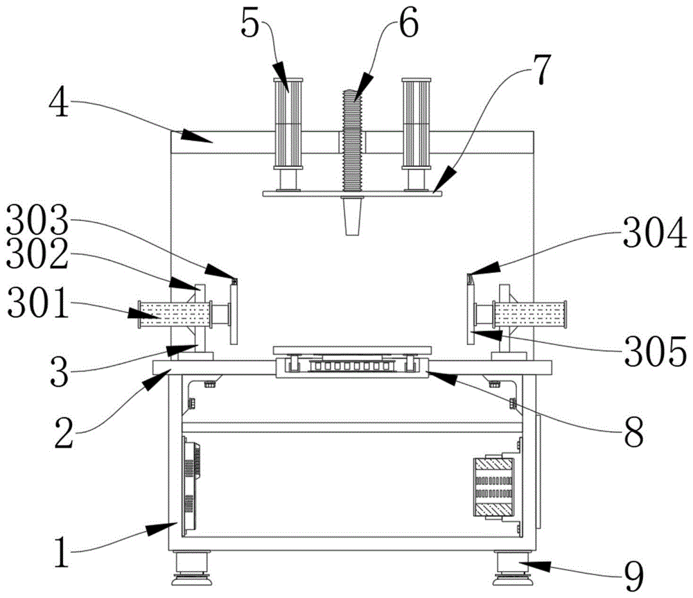
FIG. 1 is a schematic front sectional view of the present invention;
FIG. 2 is a schematic side view of the present invention;
FIG. 3 is a schematic three-dimensional structure of the limiting mechanism of the present invention;
FIG. 4 is a schematic structural view of a front cross section of the measuring mechanism of the present invention;
FIG. 5 is a schematic side sectional view of the adjusting structure of the present invention.
The reference numerals in the figures illustrate: 1. a cabinet body; 2. a table top; 3. a limiting mechanism; 301. an electric push rod; 302. mounting a plate; 303. an infrared emitter; 304. an infrared receiver; 305. a limiting plate; 4. a ceiling; 5. a pneumatic push rod; 6. a feed pipe; 7. a connecting plate; 8. a measuring mechanism; 801. a housing; 802. a pressure sensor; 803. a guide groove; 804. a guide bar; 805. a top plate; 9. an adjustment structure; 901. a rubber pad; 902. a housing; 903. rotating the block; 904. a screw; 905. a solenoid; 10. and a single chip microcomputer.
Detailed Description
In order to make the objects, technical solutions and advantages of the embodiments of the present invention clearer, the technical solutions in the embodiments of the present invention will be clearly and completely described below with reference to the drawings in the embodiments of the present invention, and it is obvious that the described embodiments are some, but not all, embodiments of the present invention. All other embodiments, which can be derived by a person skilled in the art from the embodiments given herein without any inventive step, are within the scope of the present invention.
In the description of the present invention, it should be noted that, unless otherwise explicitly specified or limited, the terms "mounted," "connected," and "connected" are to be construed broadly, e.g., as meaning either a fixed connection, a removable connection, or an integral connection; can be mechanically or electrically connected; they may be connected directly or indirectly through intervening media, or they may be interconnected between two elements. The specific meanings of the above terms in the present invention can be understood in specific cases to those skilled in the art.
Referring to fig. 1-5, an embodiment of the present invention is shown: an epoxy resin AB glue automatic filling machine comprises a cabinet body 1, a table board 2 and a ceiling 4, wherein the bottom end of the cabinet body 1 is provided with an adjusting structure 9, a single chip microcomputer 10 is installed on one side of the cabinet body 1, the top end of the cabinet body 1 is fixed with the table board 2, the top end of the table board 2 is provided with a measuring mechanism 8, the top end of the table board 2 is provided with a limiting mechanism 3, one side of the top end of the table board 2 is fixed with the ceiling 4, a pneumatic push rod 5 is installed inside the ceiling 4, the type of the pneumatic push rod 5 can be J64RT2UNIVER, the input end of the pneumatic push rod 5 is electrically connected with the output end of the single chip microcomputer 10 through a wire, the bottom end of the pneumatic push rod 5 is fixed with a connecting plate 7, a feeding pipe 6 is installed inside the connecting plate 7, the limiting mechanism 3 comprises an electric push rod 301, a mounting plate 302, an infrared emitter 303, an infrared receiver 304 and a limiting plate 305, the mounting plates 302 are installed on two sides of the top end of the table board 2, an electric push rod 301 is installed inside the mounting plate 302, the model of the electric push rod 301 can be SKW-1-24, the input end of the electric push rod 301 is electrically connected with the output end of the single chip microcomputer 10 through a conducting wire, a limiting plate 305 is fixed on one side of the electric push rod 301, an infrared emitter 303 is installed at the top end of the limiting plate 305, the model of the infrared emitter 303 can be KEL-504C, the input end of the infrared emitter 303 is electrically connected with the output end of the single chip microcomputer 10 through a conducting wire, an infrared receiver 304 is arranged on one side of the infrared emitter 303, the model of the infrared receiver 304 can be VS1838B, the input end of the infrared receiver 304 is electrically connected with the output end of the single chip microcomputer 10 through a conducting wire, the infrared emitter 303 and the infrared receiver 304 are positioned on the same horizontal center line, so that the infrared emitter 303 can receive infrared rays generated by the infrared emitter 304, the limiting plates 305 are symmetrically distributed on the vertical center line of the table top 2.
Specifically, as shown in fig. 1, fig. 2 and fig. 3, during the use, shelter from the infrared ray that infrared emitter 303 produced through the filling bottle, make infrared receiver 304 stop receiving infrared ray signal and with data transmission to singlechip 10, singlechip 10 control electric putter 301 starts immediately, makes electric putter 301 produce thrust and promotes limiting plate 305 and remove to the filling bottle, controls applying thrust jointly of two sets of limiting plates 305, promotes the filling bottle and removes to the inlet pipe 6 under, with the position restriction of filling bottle.
The measuring mechanism 8 comprises a shell 801, a pressure sensor 802, a guide groove 803, a guide rod 804 and a top plate 805, wherein the shell 801 is installed inside the table top 2, the pressure sensor 802 is installed inside the shell 801, the type of the pressure sensor 802 can be CYYZ13, the input end of the pressure sensor 802 is electrically connected with the output end of the single chip microcomputer 10 through a lead, the top end of the pressure sensor 802 is fixed with the top plate 805, the guide groove 803 is installed on each of two sides of the pressure sensor 802, the guide rod 804 is inserted inside the guide groove 803, a sliding structure is formed between the guide rod 804 and the guide groove 803, the guide groove 803 limits the moving direction of the guide rod 804, the shaking of the guide rod 804 during moving is reduced, the shell 801 and the table top 2 are of a welding integrated structure, and the shell 801 and the table top 2 are connected stably and are not prone to falling off.
Specifically, as shown in fig. 1, 2 and 4, when the filling machine is used, the top plate 805 supports the weight of the filling bottle and the epoxy resin AB filled in the filling bottle, the top plate 805 presses the pressure sensor 802 to measure the weight of the filling bottle and the epoxy resin AB filled in the filling bottle, meanwhile, the pressure sensor 802 feeds data back to the single chip microcomputer 10, the single chip microcomputer 10 stops filling in time according to the measured data, and the pressure sensor 802 slides in the guide rod 804, so that the top plate 805 is kept stable, and shaking is reduced.
Adjusting structure 9 includes rubber pad 901, cover shell 902, change piece 903, screw rod 904 and solenoid 905, screw rod 904 is all fixed in the bottom of the cabinet body 1, screw rod 904's inside is inserted and is equipped with solenoid 905, and solenoid 905's bottom mounting has a commentaries on classics piece 903, the outside cover of commentaries on classics piece 903 is equipped with cover shell 902, the bottom mounting of cover shell 902 has rubber pad 901, be provided with the external screw thread on solenoid 905's the lateral wall, and screw rod 904's inside is provided with the internal thread that mutually supports with the external screw thread, make solenoid 905 can remove along screw rod 904's inner wall through the meshing of screw thread, the lift of solenoid 905 has been realized.
Specifically, as shown in fig. 1, 2 and 5, in use, the rotating block 903 is rotated to drive the screw tube 905 to rotate, then the screw tube 905 moves along the inner wall of the screw 904 through the engagement of the screw threads, the exposed length of the screw tube 905 is adjusted to enable the screw tube 905 to drive the rubber pad 901 to contact with the ground, so that the device is placed stably, the rotating block 903 rotates in the casing 902 to prevent the rubber pad 901 from moving when the rotating block 903 rotates, and the device is supported.
The working principle is as follows: when the filling bottle limiting device is used, the filling bottle limiting device is externally connected with a power supply, firstly, the filling bottle limiting device is moved to a use area, then, filling bottles are placed at the top end of the table board 2, infrared rays generated by the infrared emitter 303 are shielded through the filling bottles, the infrared receiver 304 stops receiving infrared signals and transmits data to the single chip microcomputer 10, then, the single chip microcomputer 10 controls the electric push rod 301 to be started, the electric push rod 301 generates thrust to push the limiting plates 305 to move towards the filling bottles, the thrust is applied to the left limiting plate 305 and the right limiting plate 305 together, the filling bottles are pushed to move to the position right below the feeding pipe 6, the positions of the filling bottles are limited, and the limitation on the filling bottles is completed.
Secondly, promote connecting plate 7 through pneumatic push rod 5 and drive inlet pipe 6 and filling bottle contact, make inlet pipe 6 glue epoxy AB and pour into the inside of filling bottle, support filling bottle and the weight of epoxy AB glue of packing into through roof 805, make roof 805 extrusion pressure sensor 802 measure filling bottle and the weight of packing into epoxy AB glue, pressure sensor 802 feeds back data to singlechip 10 simultaneously, make singlechip 10 according to the timely stopping of measured data filling, slide in the inside of guide bar 804 through pressure sensor 802, make roof 805 keep stable, reduce and rock, accomplish the measurement to the filling bottle.
Finally, when the device is placed unstably, through rotatory commentaries on classics piece 903, make commentaries on classics piece 903 drive solenoid 905 rotatory, the solenoid 905 removes along the inner wall of screw 904 through the meshing of screw thread next, adjust the length that exposes of solenoid 905, make solenoid 905 can drive rubber pad 901 and ground contact, the firm that makes the device place, rotate in the inside of cover shell 902 through changeing piece 903, make can not drive rubber pad 901 and remove when rotatory commentaries on classics piece 903, accomplish the support to the device, the use work of this epoxy AB glue automatic filling machine is finally accomplished.
In the description of the present invention, it should be noted that, unless otherwise explicitly specified or limited, the terms "mounted," "connected," and "connected" are to be construed broadly, e.g., as meaning either a fixed connection, a removable connection, or an integral connection; can be mechanically or electrically connected; they may be connected directly or indirectly through intervening media, or they may be interconnected between two elements. The specific meanings of the above terms in the present invention can be understood in specific cases to those skilled in the art.
The above-described embodiments of the apparatus are merely illustrative, and the units described as separate parts may or may not be physically separate, and parts displayed as units may or may not be physical units, may be located in one place, or may be distributed on a plurality of network units. Some or all of the modules may be selected according to actual needs to achieve the purpose of the solution of the present embodiment. One of ordinary skill in the art can understand and implement it without inventive effort.
Finally, it should be noted that: the above examples are only intended to illustrate the technical solution of the present invention, but not to limit it; although the present invention has been described in detail with reference to the foregoing embodiments, it will be understood by those of ordinary skill in the art that: the technical solutions described in the foregoing embodiments may still be modified, or some technical features may be equivalently replaced; and such modifications or substitutions do not depart from the spirit and scope of the corresponding technical solutions of the embodiments of the present invention.

Claims (7)

1.一种环氧树脂AB胶自动灌装机,包括柜体(1)、台面(2)和顶棚(4),其特征在于:所述柜体(1)的底端均设置有调节结构(9),所述柜体(1)的一侧安装有单片机(10),所述柜体(1)的顶端固定有台面(2);1. An automatic filling machine for epoxy resin AB glue, comprising a cabinet body (1), a table top (2) and a ceiling (4), characterized in that: the bottom end of the cabinet body (1) is provided with an adjustment structure (9), a single chip (10) is installed on one side of the cabinet body (1), and a table top (2) is fixed on the top of the cabinet body (1); 所述台面(2)顶端的设置有测量机构(8),所述台面(2)的顶端设置有限位机构(3),所述台面(2)顶端的一侧固定有顶棚(4);A measuring mechanism (8) is provided on the top of the table top (2), a limiting mechanism (3) is provided on the top of the table top (2), and a ceiling (4) is fixed on one side of the top of the table top (2); 所述顶棚(4)的内部均安装有气动推杆(5),且气动推杆(5)的底端固定有连接板(7),且连接板(7)的内部安装有进料管(6)。A pneumatic push rod (5) is installed inside the ceiling (4), a connecting plate (7) is fixed at the bottom end of the pneumatic push rod (5), and a feeding pipe (7) is installed inside the connecting plate (7). 6). 2.根据权利要求1所述的一种环氧树脂AB胶自动灌装机,其特征在于:所述限位机构(3)包括电动推杆(301)、安装板(302)、红外线发射器(303)、红外线接收器(304)和限位板(305),所述安装板(302)安装在台面(2)顶端的两侧,所述安装板(302)的内部安装有电动推杆(301),且电动推杆(301)的一侧固定有限位板(305),所述限位板(305)的顶端安装有红外线发射器(303),且红外线发射器(303)的一侧设置有红外线接收器(304)。2. An automatic filling machine for epoxy resin AB glue according to claim 1, characterized in that: the limiting mechanism (3) comprises an electric push rod (301), a mounting plate (302), an infrared emitter (303), an infrared receiver (304) and a limiting plate (305), the mounting plate (302) is installed on both sides of the top of the table top (2), and an electric push rod is installed inside the mounting plate (302). (301), and a limiting plate (305) is fixed on one side of the electric push rod (301), and an infrared emitter (303) is installed on the top of the limiting plate (305), and one of the infrared emitters (303) An infrared receiver (304) is provided on the side. 3.根据权利要求2所述的一种环氧树脂AB胶自动灌装机,其特征在于:所述红外线发射器(303)与红外线接收器(304)位于同时水平中心线上,所述限位板(305)在台面(2)的垂直中心线上呈对称分布。3. A kind of epoxy resin AB glue automatic filling machine according to claim 2, is characterized in that: described infrared emitter (303) and infrared receiver (304) are located on the horizontal center line at the same time, and described limit The position plates (305) are symmetrically distributed on the vertical centerline of the table top (2). 4.根据权利要求1所述的一种环氧树脂AB胶自动灌装机,其特征在于:所述测量机构(8)包括壳体(801)、压力传感器(802)、导向槽(803)、导向杆(804)和顶板(805),所述壳体(801)安装在台面(2)的内部,所述壳体(801)的内部安装有压力传感器(802),且压力传感器(802)的顶端固定有顶板(805),所述压力传感器(802)的两侧均安装有导向槽(803),且导向槽(803)的内部插设有导向杆(804)。4. The epoxy resin AB glue automatic filling machine according to claim 1, wherein the measuring mechanism (8) comprises a casing (801), a pressure sensor (802), a guide groove (803) , a guide rod (804) and a top plate (805), the housing (801) is installed inside the table (2), a pressure sensor (802) is installed inside the housing (801), and the pressure sensor (802) A top plate (805) is fixed on the top end of the pressure sensor (802), guide grooves (803) are installed on both sides of the pressure sensor (802), and a guide rod (804) is inserted in the guide groove (803). 5.根据权利要求4所述的一种环氧树脂AB胶自动灌装机,其特征在于:所述导向杆(804)与导向槽(803)之间构成滑动结构,所述壳体(801)与台面(2)之间呈焊接一体化结构。5. The epoxy resin AB glue automatic filling machine according to claim 4, wherein a sliding structure is formed between the guide rod (804) and the guide groove (803), and the casing (801) ) and the table top (2) in a welded integrated structure. 6.根据权利要求1所述的一种环氧树脂AB胶自动灌装机,其特征在于:所述调节结构(9)包括橡胶垫(901)、套壳(902)、转块(903)、螺杆(904)和螺管(905),所述螺杆(904)均固定在柜体(1)的底端,所述螺杆(904)的内部插设有螺管(905),且螺管(905)的底端固定有转块(903),所述转块(903)的外侧套设有套壳(902),所述套壳(902)的底端固定有橡胶垫(901)。6. An automatic filling machine for epoxy resin AB glue according to claim 1, characterized in that: the adjustment structure (9) comprises a rubber pad (901), a casing (902), a turning block (903) , a screw (904) and a screw (905), the screw (904) is fixed on the bottom end of the cabinet (1), the screw (904) is inserted with a screw (905), and the screw (904) A rotating block (903) is fixed at the bottom end of (905), a casing (902) is sleeved on the outer side of the rotating block (903), and a rubber pad (901) is fixed at the bottom end of the casing (902). 7.根据权利要求6所述的一种环氧树脂AB胶自动灌装机,其特征在于:所述螺管(905)的外侧壁上设置有外螺纹,且螺杆(904)的内部设置有与外螺纹相互配合的内螺纹。7. An automatic filling machine for epoxy resin AB glue according to claim 6, characterized in that: an outer thread is provided on the outer side wall of the spiral tube (905), and an interior of the screw (904) is provided with an external thread. Internal threads that cooperate with external threads.
CN202111175150.2A 2021-10-09 2021-10-09 Epoxy AB glue automatic filling machine Pending CN113772611A (en)

Priority Applications (1)

Application Number Priority Date Filing Date Title
CN202111175150.2A CN113772611A (en) 2021-10-09 2021-10-09 Epoxy AB glue automatic filling machine

Applications Claiming Priority (1)

Application Number Priority Date Filing Date Title
CN202111175150.2A CN113772611A (en) 2021-10-09 2021-10-09 Epoxy AB glue automatic filling machine

Publications (1)

Publication Number Publication Date
CN113772611A true CN113772611A (en) 2021-12-10

Family

ID=78855086

Family Applications (1)

Application Number Title Priority Date Filing Date
CN202111175150.2A Pending CN113772611A (en) 2021-10-09 2021-10-09 Epoxy AB glue automatic filling machine

Country Status (1)

Country Link
CN (1) CN113772611A (en)

Cited By (1)

* Cited by examiner, † Cited by third party
Publication number Priority date Publication date Assignee Title
CN116715180A (en) * 2023-07-10 2023-09-08 江苏威名新材料有限公司 Energy-saving environment-friendly silicone weather-resistant glue separate-packaging filter device

Citations (7)

* Cited by examiner, † Cited by third party
Publication number Priority date Publication date Assignee Title
CN106795995A (en) * 2014-08-26 2017-05-31 迪特尔·拉姆绍尔 Articulating adjustable feet for machines or equipment
CN206486273U (en) * 2016-12-30 2017-09-12 库珀(天津)科技有限公司 A kind of self-action Lubricating oil filling machine
CN208585437U (en) * 2018-06-12 2019-03-08 中山市多纷洗涤用品有限公司 An automatic shampoo filling equipment for the production of toiletries
CN210127079U (en) * 2019-05-11 2020-03-06 湖北省麦吉丽生物科技有限公司 Filling device is used in cosmetics production
CN111908402A (en) * 2020-07-21 2020-11-10 南京昱晟机器人科技有限公司 Industrial antifouling type liquid filling robot
CN212387715U (en) * 2020-03-19 2021-01-22 广州腾度实业有限公司 Filling device is used in cosmetics production
CN216191000U (en) * 2021-10-09 2022-04-05 东莞市永固绝缘材料有限公司 Epoxy AB glue automatic filling machine

Patent Citations (7)

* Cited by examiner, † Cited by third party
Publication number Priority date Publication date Assignee Title
CN106795995A (en) * 2014-08-26 2017-05-31 迪特尔·拉姆绍尔 Articulating adjustable feet for machines or equipment
CN206486273U (en) * 2016-12-30 2017-09-12 库珀(天津)科技有限公司 A kind of self-action Lubricating oil filling machine
CN208585437U (en) * 2018-06-12 2019-03-08 中山市多纷洗涤用品有限公司 An automatic shampoo filling equipment for the production of toiletries
CN210127079U (en) * 2019-05-11 2020-03-06 湖北省麦吉丽生物科技有限公司 Filling device is used in cosmetics production
CN212387715U (en) * 2020-03-19 2021-01-22 广州腾度实业有限公司 Filling device is used in cosmetics production
CN111908402A (en) * 2020-07-21 2020-11-10 南京昱晟机器人科技有限公司 Industrial antifouling type liquid filling robot
CN216191000U (en) * 2021-10-09 2022-04-05 东莞市永固绝缘材料有限公司 Epoxy AB glue automatic filling machine

Cited By (2)

* Cited by examiner, † Cited by third party
Publication number Priority date Publication date Assignee Title
CN116715180A (en) * 2023-07-10 2023-09-08 江苏威名新材料有限公司 Energy-saving environment-friendly silicone weather-resistant glue separate-packaging filter device
CN116715180B (en) * 2023-07-10 2024-01-02 江苏威名新材料有限公司 Energy-saving environment-friendly silicone weather-resistant glue separate-packaging filter device

Similar Documents

Publication Publication Date Title
CN216191000U (en) Epoxy AB glue automatic filling machine
CN107910287B (en) A fully automatic LED packaging machine
CN117922878B (en) Deoxidizer packaging device and packaging process thereof
CN113772611A (en) Epoxy AB glue automatic filling machine
CN113347870B (en) LED chip mounter feeding agencies
CN211504130U (en) Engineering surveying instrument positioning device
CN205461132U (en) Solid -phase extraction post assembly machine
CN116551352A (en) Bearing processing, assembling and testing integrated machine
CN115870654A (en) Automatic processing device for chip
CN211003774U (en) Positioning and winding device of printing machine
CN209973635U (en) Paper plugging device for plastic film production
CN218288203U (en) High-efficient gel candy filling machine
CN222684278U (en) Liquid filling corking machine
CN210005091U (en) self-adaptive belt scale weighing system
CN211678596U (en) A dispensing device for liquid crystal display production
CN223467737U (en) Conveyer belt adjustment mechanism
CN222808723U (en) Belt conveyor convenient to move
CN216687443U (en) Insecticide processing filling positioning mechanism
CN223215628U (en) Automatic loading device for bearing balls
CN221235196U (en) Automatic cap screwing machine
CN207876860U (en) A kind of rice production feeding device
CN215287959U (en) Filling, labeling and weighing synchronous filling machine
CN211636575U (en) Titration apparatus for pharmacology experiments
CN216800430U (en) A blank pressing point gum machine for car horn production line
CN216377405U (en) An automatic canning and sealing machine

Legal Events

Date Code Title Description
PB01 Publication
PB01 Publication
SE01 Entry into force of request for substantive examination
WD01 Invention patent application deemed withdrawn after publication

Application publication date: 20211210