CN113774565B - Needling mechanism of needling machine - Google Patents
Needling mechanism of needling machine Download PDFInfo
- Publication number
- CN113774565B CN113774565B CN202111056448.1A CN202111056448A CN113774565B CN 113774565 B CN113774565 B CN 113774565B CN 202111056448 A CN202111056448 A CN 202111056448A CN 113774565 B CN113774565 B CN 113774565B
- Authority
- CN
- China
- Prior art keywords
- oil
- transmission
- guide sleeve
- push rod
- rotating shafts
- Prior art date
- Legal status (The legal status is an assumption and is not a legal conclusion. Google has not performed a legal analysis and makes no representation as to the accuracy of the status listed.)
- Active
Links
- 230000007246 mechanism Effects 0.000 title claims abstract description 69
- 230000005540 biological transmission Effects 0.000 claims abstract description 224
- 230000003014 reinforcing effect Effects 0.000 claims abstract description 16
- 229910000838 Al alloy Inorganic materials 0.000 claims abstract description 8
- 229910000861 Mg alloy Inorganic materials 0.000 claims abstract description 6
- 239000003921 oil Substances 0.000 claims description 213
- 239000010687 lubricating oil Substances 0.000 claims description 79
- 238000003860 storage Methods 0.000 claims description 45
- 238000000429 assembly Methods 0.000 claims description 43
- 230000000712 assembly Effects 0.000 claims description 43
- 238000009434 installation Methods 0.000 claims description 15
- 230000001050 lubricating effect Effects 0.000 claims description 14
- 238000012546 transfer Methods 0.000 claims description 11
- ATJFFYVFTNAWJD-UHFFFAOYSA-N Tin Chemical compound [Sn] ATJFFYVFTNAWJD-UHFFFAOYSA-N 0.000 claims description 9
- 229910000897 Babbitt (metal) Inorganic materials 0.000 claims description 7
- 229910001018 Cast iron Inorganic materials 0.000 claims description 7
- 238000009950 felting Methods 0.000 claims description 7
- 238000004519 manufacturing process Methods 0.000 claims description 7
- 229910045601 alloy Inorganic materials 0.000 claims description 5
- 239000000956 alloy Substances 0.000 claims description 5
- 229910001008 7075 aluminium alloy Inorganic materials 0.000 claims description 4
- 230000009286 beneficial effect Effects 0.000 abstract description 4
- 238000000034 method Methods 0.000 description 17
- 230000000694 effects Effects 0.000 description 15
- 230000008569 process Effects 0.000 description 14
- 238000001467 acupuncture Methods 0.000 description 13
- 238000005728 strengthening Methods 0.000 description 11
- 230000017525 heat dissipation Effects 0.000 description 9
- 238000005461 lubrication Methods 0.000 description 8
- 238000004080 punching Methods 0.000 description 8
- 230000002349 favourable effect Effects 0.000 description 7
- 239000000835 fiber Substances 0.000 description 7
- 230000002159 abnormal effect Effects 0.000 description 5
- 230000006872 improvement Effects 0.000 description 5
- 238000012423 maintenance Methods 0.000 description 5
- 238000005266 casting Methods 0.000 description 4
- 230000008878 coupling Effects 0.000 description 4
- 238000010168 coupling process Methods 0.000 description 4
- 238000005859 coupling reaction Methods 0.000 description 4
- 238000005086 pumping Methods 0.000 description 4
- 238000001816 cooling Methods 0.000 description 3
- 239000000314 lubricant Substances 0.000 description 3
- 239000000463 material Substances 0.000 description 3
- 230000002093 peripheral effect Effects 0.000 description 3
- 238000012545 processing Methods 0.000 description 3
- 238000010586 diagram Methods 0.000 description 2
- 238000002474 experimental method Methods 0.000 description 2
- 230000005484 gravity Effects 0.000 description 2
- 230000020169 heat generation Effects 0.000 description 2
- 239000007769 metal material Substances 0.000 description 2
- 238000004064 recycling Methods 0.000 description 2
- 238000007789 sealing Methods 0.000 description 2
- 230000009471 action Effects 0.000 description 1
- 238000007792 addition Methods 0.000 description 1
- 230000003028 elevating effect Effects 0.000 description 1
- 238000005516 engineering process Methods 0.000 description 1
- 229910001095 light aluminium alloy Inorganic materials 0.000 description 1
- 229910000706 light magnesium alloy Inorganic materials 0.000 description 1
- 238000003754 machining Methods 0.000 description 1
- 238000012986 modification Methods 0.000 description 1
- 230000004048 modification Effects 0.000 description 1
- 239000004745 nonwoven fabric Substances 0.000 description 1
- 239000003129 oil well Substances 0.000 description 1
- 239000004576 sand Substances 0.000 description 1
- 238000006467 substitution reaction Methods 0.000 description 1
Images






Classifications
-
- D—TEXTILES; PAPER
- D04—BRAIDING; LACE-MAKING; KNITTING; TRIMMINGS; NON-WOVEN FABRICS
- D04H—MAKING TEXTILE FABRICS, e.g. FROM FIBRES OR FILAMENTARY MATERIAL; FABRICS MADE BY SUCH PROCESSES OR APPARATUS, e.g. FELTS, NON-WOVEN FABRICS; COTTON-WOOL; WADDING ; NON-WOVEN FABRICS FROM STAPLE FIBRES, FILAMENTS OR YARNS, BONDED WITH AT LEAST ONE WEB-LIKE MATERIAL DURING THEIR CONSOLIDATION
- D04H18/00—Needling machines
- D04H18/02—Needling machines with needles
-
- F—MECHANICAL ENGINEERING; LIGHTING; HEATING; WEAPONS; BLASTING
- F16—ENGINEERING ELEMENTS AND UNITS; GENERAL MEASURES FOR PRODUCING AND MAINTAINING EFFECTIVE FUNCTIONING OF MACHINES OR INSTALLATIONS; THERMAL INSULATION IN GENERAL
- F16H—GEARING
- F16H57/00—General details of gearing
- F16H57/02—Gearboxes; Mounting gearing therein
-
- F—MECHANICAL ENGINEERING; LIGHTING; HEATING; WEAPONS; BLASTING
- F16—ENGINEERING ELEMENTS AND UNITS; GENERAL MEASURES FOR PRODUCING AND MAINTAINING EFFECTIVE FUNCTIONING OF MACHINES OR INSTALLATIONS; THERMAL INSULATION IN GENERAL
- F16H—GEARING
- F16H57/00—General details of gearing
- F16H57/02—Gearboxes; Mounting gearing therein
- F16H57/021—Shaft support structures, e.g. partition walls, bearing eyes, casing walls or covers with bearings
-
- F—MECHANICAL ENGINEERING; LIGHTING; HEATING; WEAPONS; BLASTING
- F16—ENGINEERING ELEMENTS AND UNITS; GENERAL MEASURES FOR PRODUCING AND MAINTAINING EFFECTIVE FUNCTIONING OF MACHINES OR INSTALLATIONS; THERMAL INSULATION IN GENERAL
- F16H—GEARING
- F16H57/00—General details of gearing
- F16H57/02—Gearboxes; Mounting gearing therein
- F16H57/023—Mounting or installation of gears or shafts in the gearboxes, e.g. methods or means for assembly
-
- F—MECHANICAL ENGINEERING; LIGHTING; HEATING; WEAPONS; BLASTING
- F16—ENGINEERING ELEMENTS AND UNITS; GENERAL MEASURES FOR PRODUCING AND MAINTAINING EFFECTIVE FUNCTIONING OF MACHINES OR INSTALLATIONS; THERMAL INSULATION IN GENERAL
- F16H—GEARING
- F16H57/00—General details of gearing
- F16H57/02—Gearboxes; Mounting gearing therein
- F16H57/028—Gearboxes; Mounting gearing therein characterised by means for reducing vibration or noise
-
- F—MECHANICAL ENGINEERING; LIGHTING; HEATING; WEAPONS; BLASTING
- F16—ENGINEERING ELEMENTS AND UNITS; GENERAL MEASURES FOR PRODUCING AND MAINTAINING EFFECTIVE FUNCTIONING OF MACHINES OR INSTALLATIONS; THERMAL INSULATION IN GENERAL
- F16H—GEARING
- F16H57/00—General details of gearing
- F16H57/04—Features relating to lubrication or cooling or heating
- F16H57/0412—Cooling or heating; Control of temperature
- F16H57/0415—Air cooling or ventilation; Heat exchangers; Thermal insulations
- F16H57/0417—Heat exchangers adapted or integrated in the gearing
-
- F—MECHANICAL ENGINEERING; LIGHTING; HEATING; WEAPONS; BLASTING
- F16—ENGINEERING ELEMENTS AND UNITS; GENERAL MEASURES FOR PRODUCING AND MAINTAINING EFFECTIVE FUNCTIONING OF MACHINES OR INSTALLATIONS; THERMAL INSULATION IN GENERAL
- F16H—GEARING
- F16H57/00—General details of gearing
- F16H57/04—Features relating to lubrication or cooling or heating
- F16H57/0434—Features relating to lubrication or cooling or heating relating to lubrication supply, e.g. pumps; Pressure control
- F16H57/0435—Pressure control for supplying lubricant; Circuits or valves therefor
-
- F—MECHANICAL ENGINEERING; LIGHTING; HEATING; WEAPONS; BLASTING
- F16—ENGINEERING ELEMENTS AND UNITS; GENERAL MEASURES FOR PRODUCING AND MAINTAINING EFFECTIVE FUNCTIONING OF MACHINES OR INSTALLATIONS; THERMAL INSULATION IN GENERAL
- F16H—GEARING
- F16H57/00—General details of gearing
- F16H57/04—Features relating to lubrication or cooling or heating
- F16H57/0434—Features relating to lubrication or cooling or heating relating to lubrication supply, e.g. pumps; Pressure control
- F16H57/0441—Arrangements of pumps
-
- F—MECHANICAL ENGINEERING; LIGHTING; HEATING; WEAPONS; BLASTING
- F16—ENGINEERING ELEMENTS AND UNITS; GENERAL MEASURES FOR PRODUCING AND MAINTAINING EFFECTIVE FUNCTIONING OF MACHINES OR INSTALLATIONS; THERMAL INSULATION IN GENERAL
- F16H—GEARING
- F16H57/00—General details of gearing
- F16H57/04—Features relating to lubrication or cooling or heating
- F16H57/0467—Elements of gearings to be lubricated, cooled or heated
- F16H57/0469—Bearings or seals
- F16H57/0471—Bearing
-
- F—MECHANICAL ENGINEERING; LIGHTING; HEATING; WEAPONS; BLASTING
- F16—ENGINEERING ELEMENTS AND UNITS; GENERAL MEASURES FOR PRODUCING AND MAINTAINING EFFECTIVE FUNCTIONING OF MACHINES OR INSTALLATIONS; THERMAL INSULATION IN GENERAL
- F16H—GEARING
- F16H57/00—General details of gearing
- F16H57/02—Gearboxes; Mounting gearing therein
- F16H2057/02039—Gearboxes for particular applications
- F16H2057/02069—Gearboxes for particular applications for industrial applications
Landscapes
- Engineering & Computer Science (AREA)
- General Engineering & Computer Science (AREA)
- Mechanical Engineering (AREA)
- Textile Engineering (AREA)
- General Details Of Gearings (AREA)
Abstract
The invention relates to a needling mechanism of a needling machine, which comprises a transmission case, at least one transmission shaft component and at least one pricking pin component, wherein the transmission shaft component is rotatably arranged in the transmission case; the transmission shaft assembly is connected with the pricking pin assembly through a plurality of lifting transmission mechanisms, each lifting transmission mechanism comprises an eccentric wheel, a guide sleeve, a push rod and a rocker arm, a first mounting hole is formed in the first end of the rocker arm, the eccentric wheel is mounted on the transmission shaft assembly and is sleeved in the first mounting hole through an eccentric wheel bearing, the push rod is located in the guide sleeve, the first end of the push rod is hinged to the second end of the rocker arm, and the second end of the push rod is connected with the pricking pin assembly; the rocker arm is made of aluminum alloy or magnesium alloy; the first end of the rocker arm is provided with a plurality of reinforcing ribs which are sequentially arranged from front to back, and the height value of each reinforcing rib is more than 20 mm. The rocker arm in the needling mechanism has firm structure, is not easy to deform, has small weight, and is beneficial to keeping stable operation of the lifting transmission mechanism, thereby being beneficial to improving the needling frequency.
Description
Technical Field
The invention relates to a needle machine, in particular to a needling mechanism of the needle machine.
Background
The needle punching method is one of the most important processing technologies of the non-woven fabric, and the needle punching mechanism is a key component of a needle punching machine. Generally, the more times the needling mechanism performs a needling operation per unit time (i.e., the higher the needling frequency), the higher the needling density (the number of needling operations per unit area), the better the quality of the web obtained, and the higher the production efficiency. Therefore, the magnitude of the needling frequency is one of the important factors affecting the product quality.
In the existing needle loom, the needle mechanism generally includes a transmission case, at least one transmission shaft assembly and at least one needle assembly, wherein the transmission shaft assembly is rotatably installed in the transmission case and is in a front-back direction (generally, the transmission shaft assembly is connected with the transmission case through a plurality of transmission bearings); the pricking pin component is the same as and corresponds to the transmission shaft component in number one to one, the transmission shaft component is connected with the pricking pin component through a plurality of lifting transmission mechanisms, each lifting transmission mechanism comprises an eccentric wheel, a guide sleeve, a push rod and a rocker arm, the eccentric wheel is fixedly mounted on the transmission shaft component, the first end of the rocker arm is sleeved on the eccentric wheel (generally, the first end of the rocker arm is provided with a mounting hole, the mounting hole is sleeved on the eccentric wheel through an eccentric wheel bearing), the guide sleeve is fixedly mounted on a transmission box and moves up and down, the push rod is located in the guide sleeve, the first end of the push rod is hinged to the second end of the rocker arm, and the second end of the push rod is connected with the pricking pin component. The needle assembly typically comprises a needle bar, a needle plate fixedly mounted on the needle bar, and a plurality of needles arranged on the needle plate (the needles are typically distributed evenly on the needle plate), wherein the needle bar is connected to the push rod. When the transmission shaft assembly rotates, the eccentric wheels fixed on the transmission shaft assembly are driven to rotate, the eccentric wheels drive the needle assembly to do reciprocating linear motion through the rocker arm and the push rod, repeated needling is carried out on the fiber web, and the fluffy fiber web is solidified through the needling. However, the rocker arm is generally made of cast iron, and in order to ensure that the rocker arm has a firm structure and is not easy to deform, the wall of the mounting hole of the rocker arm needs to have a large thickness, so that the whole weight of the rocker arm is heavy, and therefore, the lifting transmission mechanism can generate a large working reciprocating inertia force during high-speed operation, so that the needling machine generates severe vibration and shaking and generates great noise; the needling machine produces violent vibration and shaking during working, which seriously affects the quality and yield of the needled product.
In addition, the mounting hole of the first end of the rocker arm generally comprises a first through hole and a second through hole which are sequentially communicated, the aperture of the second through hole is smaller than that of the first through hole, an annular limiting step is arranged at the joint of the second through hole and the first through hole, an annular mounting groove is formed in the inner wall of the first through hole, a check ring is mounted in the annular mounting groove, an eccentric wheel bearing is mounted in the first through hole and is positioned between the check ring and the annular limiting step, and the eccentric wheel bearing is limited.
Disclosure of Invention
The invention aims to solve the technical problem of providing a needling mechanism of a needling machine, wherein a rocker arm in the needling mechanism has firm structure, is not easy to deform, has light weight, and is beneficial to keeping stable running of a lifting transmission mechanism during high-speed needling so as to be beneficial to improving needling frequency. The technical scheme is as follows:
a needling mechanism of a needling machine comprises a transmission case, at least one transmission shaft component and at least one needle component, wherein the transmission shaft component is rotatably arranged in the transmission case and is in a front-back direction; the felting needle subassembly is the same and the one-to-one with the quantity of transmission shaft subassembly, the transmission shaft subassembly is connected with the felting needle subassembly through a plurality of lifting drive mechanisms, lifting drive mechanism includes the eccentric wheel, the guide pin bushing, push rod and rocking arm, the first end of rocking arm is equipped with the first mounting hole of trend around the trend, eccentric wheel fixed mounting is on the transmission shaft subassembly, and the eccentric wheel cup joints in first mounting hole through eccentric wheel bearing, guide pin bushing fixed mounting is on the transmission case and for trend from top to bottom, the push rod is in the guide pin bushing, the first end of push rod is articulated with the second end of rocking arm, the second end of push rod is connected with the felting needle subassembly, its characterized in that: the rocker arm is made of aluminum alloy or magnesium alloy; the first end of rocking arm is equipped with a plurality of strengthening ribs that arrange in proper order from the front to back, and each strengthening rib is followed the outer peripheral direction of first mounting hole extends, and the height value of strengthening rib is more than 20 mm.
The height value of the reinforcing ribs is as follows: and the distance from the inner end of the reinforcing rib (namely the end of the reinforcing rib close to the first mounting hole) to the outer end of the reinforcing rib (namely the end of the reinforcing rib far away from the first mounting hole) along the radial direction of the first mounting hole.
Among the above-mentioned acupuncture mechanism, the material of rocking arm is the aluminum alloy or the magnesium alloy of light, and through set up a plurality of strengthening ribs of arranging in proper order from the front to the back at the first end of rocking arm, each strengthening rib is more than 20 mm along the peripheral extension of first mounting hole and the high value of strengthening rib, can effectively reduce the wall thickness of first mounting hole under the condition that does not influence rocking arm structural strength, can effectively improve holistic structural strength of rocking arm and stability and reduce the whole weight of rocking arm, and these strengthening ribs can also play the effect of fin, make the rocking arm have good radiating effect, make rocking arm non-deformable, be favorable to elevating drive mechanism can keep the even running when carrying out high-speed acupuncture, thereby be favorable to the improvement of acupuncture frequency.
In one specific scheme, the aluminum alloy used for manufacturing the rocker arm is 7075 aluminum alloy.
In a specific scheme, the height value of the reinforcing rib is 30mm.
In a preferable scheme, two annular mounting grooves which are symmetrically arranged in the front and back are formed in the inner wall of the first mounting hole, retainer rings are mounted in the annular mounting grooves, the outer ring of the eccentric wheel bearing is sleeved in the first mounting hole and located between the two retainer rings, and the eccentric wheel is sleeved in the inner ring of the eccentric wheel bearing. By adopting the structure, the eccentric wheel bearing in the first mounting hole can be limited by the two retainer rings, so that the position of the eccentric wheel bearing is stable; and can make the overall structure longitudinal symmetry of first mounting hole, make rocking arm longitudinal symmetry when having reduced the processing degree of difficulty of first mounting hole, effectively prevent that the focus of rocking arm from appearing the skew for the operation of rocking arm is more steady, is favorable to the improvement of acupuncture frequency.
In the preferred scheme, the first end of the push rod is hinged with the second end of the rocker arm through a push rod pin shaft which runs back and forth; the second end of the rocker arm is provided with two connecting arms which are arranged side by side from front to back, the connecting arms are provided with second mounting holes which run in the front-back direction, and the two second mounting holes are respectively provided with a push rod bearing; the first end of the push rod is arranged between the two connecting arms, the first end of the push rod is provided with a third mounting hole, and the third mounting hole corresponds to the two second mounting holes in position; the push rod pin shaft is positioned in the third mounting hole and the inner rings of the two push rod bearings. By adopting the structure, the hinge between the first end of the push rod and the second end of the rocker arm can be realized by the matching between the push rod pin shaft and the two push rod bearings, and the integral structure of the rocker arm is symmetrical front and back, so that the center of gravity of the rocker arm is effectively prevented from being deviated, the operation of the rocker arm is more stable, and the needling frequency is favorably improved.
In a preferred scheme, the needle assembly comprises a needle beam, a needle plate and a plurality of needles, wherein the needle plate is fixedly arranged on the needle beam, the needles are arranged on the needle plate (the needles are usually uniformly distributed on the needle plate), and the needle beam is connected with a push rod; the needle beam is made of aluminum alloy or magnesium alloy. Therefore, the overall weight of the lifting transmission mechanism can be further reduced, and the lifting transmission mechanism can be kept to operate stably when high-speed needling is carried out.
In a preferred scheme, the needling mechanism comprises two transmission shaft assemblies arranged side by side left and right and two pricking pin assemblies arranged side by side left and right, the two pricking pin assemblies correspond to the two transmission shaft assemblies one by one, and the transmission shaft assemblies are connected with the pricking pin assemblies through a plurality of lifting transmission mechanisms; the needling mechanism also comprises a transmission device, wherein the transmission device comprises a power input shaft, a gear box, two upper rotating shafts, two lower rotating shafts, two upper gears and two lower gears; the power input shaft is rotatably arranged in the transmission case and moves forwards and backwards, and is positioned in front of the two transmission shaft assemblies; the gear box is detachably arranged in the transmission box and is positioned between the power input shaft and the two transmission shaft assemblies, the two upper rotating shafts and the two lower rotating shafts are rotatably arranged in the gear box and are in a front-back trend, the two upper rotating shafts are arranged side by side from left to right, the front end of one upper rotating shaft is detachably connected with the rear end of the power input shaft, and the axes of the two upper rotating shafts and the rear end of the power input shaft are coincident; the two lower rotating shafts are arranged on the two sides of the two upper rotating shafts side by side from left to right, the height positions of the lower rotating shafts are lower than that of the upper rotating shafts, the two lower rotating shafts correspond to the two transmission shaft assemblies one by one, the rear ends of the lower rotating shafts are detachably connected with the front ends of the corresponding transmission shaft assemblies, and the axes of the lower rotating shafts and the front ends of the corresponding transmission shaft assemblies are coincident; the two upper gears correspond to the two upper rotating shafts one by one, and the two upper gears are respectively arranged on the corresponding upper rotating shafts and are meshed with each other; the two lower gears correspond to the two lower rotating shafts one by one, the two lower gears are respectively installed on the corresponding lower rotating shafts, the lower gear on the left side is meshed with the upper gear on the left side, and the lower gear on the right side is meshed with the upper gear on the right side.
When the transmission device is installed, the two upper gears are respectively installed on the corresponding upper rotating shafts, the two lower gears are respectively installed on the corresponding lower rotating shafts, and then the two upper rotating shafts and the two lower rotating shafts are installed in the gear box; then, the gear box is installed in the transmission case, the front end of one upper rotating shaft is connected with the rear end of the power input shaft, the axes of the upper rotating shaft and the power input shaft coincide, and the rear ends of the two lower rotating shafts are respectively connected with the front ends of the corresponding transmission shaft assemblies, and the axes of the two lower rotating shafts coincide. The clearance and the centre-to-centre spacing between two last gears and two lower gears are guaranteed by the gear box, and the gear box is formed by digit control machine tool precision finishing, and the precision obtains guaranteeing, consequently, and the assembly precision is high, can effectively improve the stability of assembly effect, ensures that two lower pivots are respectively with corresponding transmission shaft subassembly accurate alignment for meshing transmission between each gear is steady, is favorable to saving the debugging time, improves assembly efficiency. In addition, because the two transmission shaft assemblies realize transmission through the meshing between the two upper gears and the two lower gears, the transmission device can adopt a gear with a smaller diameter to replace a gear with a large diameter for transmission, and a high-speed gear is converted into a medium-speed gear, so that the torque and the strength of the gear can be improved.
Usually, the front end of the power input shaft is in transmission connection with the needling drive device. When the needle punching mechanism works, the power input shaft rotates under the driving of the driving device to drive the corresponding upper rotating shaft to rotate, the other upper rotating shaft is driven to rotate through the meshing transmission between the two upper gears, the two lower rotating shafts are driven to rotate relatively through the meshing transmission between the corresponding upper gear and the corresponding lower gear, then the two transmission shaft assemblies of the needle punching mechanism are driven to rotate relatively, the needle punching assembly is driven to do reciprocating linear motion through each lifting transmission mechanism, needle punching is conducted on the fiber web repeatedly, and the fluffy fiber web is solidified through the needle punching effect.
In a more preferable embodiment, the upper gear and the lower gear are both helical gears. The bevel gear has the characteristics of stable transmission, small impact, vibration and noise and the like, so the bevel gear is widely used in high-speed heavy-load occasions and is suitable for the more precise production process in the field of acupuncture. The upper gear and the lower gear can adopt helical gears with the same specification and size (the reference circle diameter is 138 mm, and the excircle diameter is 146 mm).
In a more preferable scheme, the top of the gear box is provided with an opening, the bottom of a side plate of the gear box is provided with at least one oil discharge hole, and lubricating oil is arranged in the bottom of an inner cavity of the gear box; the upper rotating shaft is installed in the gear box through two upper bearings, the lower rotating shaft is installed in the gear box through two lower bearings, and the lower parts of the lower gear and the lower bearings are immersed in lubricating oil. When the gearbox works, lubricating oil in the lubricating oil storage container can be added into the gearbox through the opening at the top of the gearbox, and the lubricating oil flows through between the two upper gears to lubricate the two upper gears and the two upper bearings, and is finally stored at the bottom of the cavity of the gearbox; when the oil level of the lubricating oil in the gear box is higher than the position of the oil discharge hole, redundant lubricating oil can flow into the lubricating oil storage container through the oil discharge hole (the lubricating oil in the lubricating oil storage container can be conveyed to the position above a gap between the two upper gears through the oil well pump and the oil conveying pipe to realize the circulating flow of the lubricating oil), so that the oil level height of the lubricating oil in the gear box is controlled; and all soak in lubricating oil through making two lower gears, two lower bearings's lower part, both guaranteed lubricated, obtain good heat dissipation again, through the oil level height of lubricating oil in the control gear case, also guaranteed that lubricating oil can be too big to the resistance of lower gear, ensure that the transmission is more steady simultaneously.
In a further more preferable aspect, the number of the oil drain holes is plural, and each of the oil drain holes is located at the same height position. Thus, it is further ensured that the level of lubricating oil in the gear box does not exceed the height position of the oil drain hole.
In a further more preferred scheme, the gear box comprises a bottom plate, a front side plate, a rear side plate, a left side plate and a right side plate, the lower edges of the front side plate, the rear side plate, the left side plate and the right side plate are respectively connected with the corresponding edges of the bottom plate, and the upper edges of the front side plate, the rear side plate, the left side plate and the right side plate jointly enclose the opening; the oil discharge hole is formed in the front side plate or the rear side plate; the two ends of the upper rotating shaft are respectively installed on the front side plate and the rear side plate through two upper bearings, and the two ends of the lower rotating shaft are respectively installed on the front side plate and the rear side plate through two lower bearings.
In a more preferable scheme, a fixed seat is arranged on the outer side wall of the gear box, a plurality of fixing through holes which run up and down are arranged on the fixed seat, and a fixing bolt is arranged in each fixing through hole; the top of transmission case is equipped with the installing port, is equipped with a plurality of fixed screw that are used for installing each fixing bolt on the inside relevant position of transmission case. When the gear box is installed, the gear box can be placed into the transmission box from the installation opening in a hoisting mode, after the positions of the upper rotating shaft and the lower rotating shaft and the positions of the fixing bolts and the corresponding fixing screw holes are calibrated, the screw rods of the fixing bolts are screwed into the corresponding fixing screw holes, and the gear box can be fixedly installed in the transmission box.
In a more preferable scheme, the rear end of the lower rotating shaft is connected with the front end of the transmission shaft assembly through a coupling flywheel. The coupling flywheel is a disc-shaped part with large rotational inertia and has the function of storing energy so as to increase the rotational inertia and enable the transmission shaft component to rotate more stably.
In a preferred scheme, the transmission shaft assembly is rotatably arranged in the transmission case through a plurality of transmission bearings; the needling mechanism further comprises an automatic lubricating system, the automatic lubricating system further comprises an oil tank, an oil delivery pump, a plurality of oil supply joints for supplying lubricating oil to each transmission bearing, a control device and a plurality of temperature sensors for detecting the temperature of each transmission bearing, an oil inlet of the oil delivery pump is communicated with the cavity of the oil tank through a first oil delivery pipe, an inlet of each oil supply joint is communicated with an oil outlet of the oil delivery pump through a second oil delivery pipe respectively, and the second oil delivery pipe is provided with an electromagnetic switch valve; and each temperature sensor is respectively and electrically connected with the corresponding input end of the control device, and the oil delivery pump and each electromagnetic switch valve are respectively and electrically connected with the corresponding output end of the control device.
In the automatic lubricating system, an oil supply joint and a temperature sensor usually correspond to a transmission bearing, and lubricating oil is filled in an oil tank; when the oil delivery pump and each electromagnetic switch valve are in an open state, lubricating oil in the oil tank flows through the first oil delivery pipe, the oil delivery pump and each second oil delivery pipe in sequence under the pumping of the oil delivery pump to enter each oil supply joint, and the lubricating oil is supplied to each transmission bearing for lubrication and heat dissipation; the control device detects the actual temperature value of the corresponding transmission bearing through each temperature sensor and compares the actual temperature value with the upper limit value of the temperature range value set in the control device, and according to the comparison result, the control device outputs a control signal to control the oil transfer pump and each electromagnetic switch valve to be in an opening or closing state so as to control the oil supply amount to each transmission bearing, so that each transmission bearing keeps the optimal lubricating and heat dissipation effects, and each transmission bearing is in the set temperature range value.
In the working process of the needling machine, the control device enables the oil transfer pump to keep an opening state and controls each electromagnetic switch valve to be opened for a certain time at intervals and then closed: when each electromagnetic switch valve is in an open state, lubricating oil in the oil tank flows through the first oil conveying pipe, the oil conveying pump and each second oil conveying pipe in sequence under the pumping of the oil conveying pump to enter each oil supply joint, and the lubricating oil is quantitatively supplied to the corresponding transmission bearing by each oil supply joint; when each electromagnetic switch valve is in a closed state, each oil supply joint stops supplying lubricating oil to the corresponding transmission bearing, so that the lubricating oil is regularly and quantitatively supplied to each transmission bearing, each transmission bearing is in a set temperature range value, and each transmission bearing keeps the optimal lubricating and radiating effect. If the temperature of the transmission bearing rises abnormally (namely the actual temperature value is detected to exceed the upper limit value of the set temperature range value), the control device controls the electromagnetic switch valve on the second oil pipeline corresponding to the transmission bearing to be in a continuous opening state (other electromagnetic switch valves are still closed after being opened for a certain time), and the transmission bearing is subjected to rapid heat dissipation and cooling until the actual temperature value of the transmission bearing returns to the set temperature range value. The temperature range set in the control device is set by taking into account the requirement that the temperature rise is not more than 30 ℃ when the drive bearing is normally operated (i.e. the temperature of the drive bearing is at most 30 ℃ higher than the ambient temperature) and the maximum temperature of the drive bearing itself is not more than 80 ℃, for example, in the case of an ambient temperature of 30 ℃, the temperature range set may be 30 ℃ to 60 ℃ and the upper limit value of the temperature range is 60 ℃.
In a more preferable scheme, the needling mechanism further comprises a plurality of bearing seats, and each bearing seat is fixedly installed in the transmission case and sequentially arranged along the axial direction of the transmission shaft assembly; the bearing seats are the same in number and correspond to the transmission bearings one by one, mounting grooves are formed in the bearing seats, and the transmission bearings are mounted in the mounting grooves of the bearing seats; the temperature sensor, the oil supply connector and the bearing seat are the same in number and correspond to each other one by one, the temperature sensor and the oil supply connector are both installed on the groove wall of the installation groove and correspond to the position of the transmission bearing, and the outlet of the oil supply connector is located on the inner side of the installation groove. In the working process of the needling machine, lubricating oil flows into the mounting groove of the bearing seat through an outlet of the oil supply joint and lubricates a transmission bearing in the mounting groove; because transmission bearing, bearing frame are made by metal material, have good heat conductivity, controlling means accessible temperature sensor surveys the temperature value of bearing frame, comes corresponding transmission bearing's actual temperature value, and the length of time is opened to the corresponding electromagnetic switch valve of control according to this again.
In a more preferable scheme, the automatic lubricating system further comprises a human-computer interface, and the human-computer interface is connected with the corresponding input and output ends of the control device. A worker can control parameters such as the opening and closing of the oil transfer pump and each electromagnetic switch valve, the opening duration of each electromagnetic switch valve, the set temperature range value and the like through a human-computer interface, and the human-computer interface can display the actual temperature value of each transmission bearing and whether the transmission bearing is in an abnormal state or not in real time. In the working process of the needling machine, if the actual temperature value of the transmission bearing is detected to exceed the set temperature range value, the control device can control the electromagnetic switch valve on the second oil pipeline corresponding to the transmission bearing to be in a continuous opening state, and simultaneously, a human-computer interface alarms (can alarm in the forms of flashing, sound and the like to warn a worker), so that the worker is warned that the temperature of the transmission bearing rises abnormally; then, if the temperature sensor detects that the temperature of the transmission bearing returns to the set temperature range value, the control device controls the corresponding electromagnetic switch valve to be closed and enables the human-computer interface to stop alarming; if the temperature sensor detects that the temperature of the transmission bearing does not drop (the temperature is kept unchanged or rises), the transmission bearing is damaged, the control device gives an alarm continuously through a human-computer interface, maintenance personnel are reminded to handle the alarm in time, abnormal removal is waited, and larger damage is avoided.
In another more preferred scheme, the automatic lubrication system further comprises a plurality of alarms, the number of the alarms is the same as that of the transmission bearings, the alarms correspond to the transmission bearings one by one, and each alarm is electrically connected with the corresponding output end of the control device. If the actual temperature value of the transmission bearing is detected to exceed the set temperature range value, the control device controls the electromagnetic switch valve on the second oil pipeline corresponding to the transmission bearing to be in a continuous opening state, and meanwhile, the corresponding alarm gives an alarm to warn a worker that the temperature of the transmission bearing rises abnormally; then, if the temperature sensor detects that the temperature of the transmission bearing returns to a set temperature range value, the control device controls the corresponding electromagnetic switch valve to be closed and enables the corresponding alarm to stop giving an alarm; if the temperature sensor detects that the temperature of the transmission bearing does not drop (the temperature keeps unchanged or rises), the transmission bearing is damaged, the control device continuously gives an alarm to remind maintenance personnel to process in time, abnormal removal is waited, and larger damage is avoided.
Generally, the control device adopts a PLC controller or a single chip microcomputer. The worker can select the optimal oil supply amount and oil supply time through experiments, corresponding working parameters (such as the opening duration of each electromagnetic switch valve, the set temperature range value and the like) are input into the control device in advance, and the control device controls the switch of each electromagnetic switch valve in the working process of the needling machine so as to achieve the optimal lubricating and heat dissipation effects.
In a more preferable scheme, the guide sleeve comprises an outer guide sleeve seat and an inner guide sleeve, the outer guide sleeve seat is fixedly arranged on the transmission case, an installation cavity with an upper opening and a lower opening is formed in the outer guide sleeve seat, the inner guide sleeve is arranged in the installation cavity of the outer guide sleeve seat, the outer wall of the inner guide sleeve is fixedly connected with the inner wall of the outer guide sleeve seat, and a guide hole with a vertical direction is formed in the inner guide sleeve; the push rod is arranged in a guide hole of the inner guide sleeve, an oil storage gap is formed between the outer wall of the push rod and the inner wall of the guide hole, and an oil seal cover is arranged at the lower end of the outer guide sleeve seat; an oil storage tank is arranged on the inner wall of the upper part of the guide hole, and an annular groove extending along the circumferential direction of the inner wall of the middle part of the guide hole is arranged on the inner wall of the middle part of the guide hole; the upper end opening of guiding hole and the cavity bottom intercommunication of transmission case are equipped with the oil return opening on the outer guide sleeve seat lateral wall, oil return opening and oil storage clearance lower extreme intercommunication, the oil return opening through return oil pipe with the cavity intercommunication of oil tank installs the scavenge pump on the return oil pipe.
In the guide sleeve, the oil seal cover is used for sealing the lower end of the oil storage gap, so that lubricating oil cannot leak from the lower end of the outer guide sleeve seat; through set up the annular groove at the middle part inner wall of guiding hole, can form the annular oil storage chamber that is used for saving lubricating oil between the outer wall of push rod and annular groove inner wall. In the working process of the needling machine, redundant lubricating oil lubricated for each transmission bearing can drip to the bottom of a cavity of the transmission case and be stored (the oil level of the lubricating oil in the transmission case is generally slightly higher than the upper end opening of the guide hole), the lubricating oil in the transmission case can enter an oil storage tank from the upper end opening of the guide hole and be refilled into an annular oil storage cavity and an oil storage gap below the annular oil storage cavity, a lubricating oil layer is formed between the inner wall of the guide hole and the outer wall of the push rod, and the lubricating oil flowing out of an oil return opening flows back into the oil tank through an oil return pipe so as to realize the purposes of recycling and cooling the lubricating oil; the contact area between the push rod and the inner guide sleeve can be reduced by arranging the annular groove, so that the friction force between the push rod and the inner guide sleeve is reduced, the heat productivity generated by friction in the process of up-and-down reciprocating motion of the push rod in the inner guide sleeve can be effectively reduced, and the up-and-down reciprocating motion frequency of the push rod can be increased. In the process that the push rod moves downwards along the guide hole of the inner guide sleeve, the annular step at the joint of the lower side groove wall of the annular groove and the inner wall of the lower part of the guide hole forms an oil retaining ring, a large amount of lubricating oil driven by the push rod can be blocked, most of the lubricating oil is left in the annular oil storage cavity, only a small amount of lubricating oil is filled in an oil storage gap below the annular oil storage cavity, and therefore the situation that oil leakage occurs due to overlarge pressure at the oil seal position caused by the fact that the excessive lubricating oil is brought to the oil seal position by the push rod can be avoided.
In a further more preferred scheme, the guide hole is a circular through hole, the annular groove is a circular annular groove, and the center line of the annular groove is overlapped with the center line of the guide hole.
In a further more preferred scheme, a circular truncated cone-shaped opening with a large upper end and a small lower end is formed in the upper end of the guide hole of the inner guide sleeve, an oil inlet is formed in a gap between the top of the inner wall of the circular truncated cone-shaped opening and the push rod, and the oil inlet is communicated with the upper end of the oil storage tank. By adopting the structure, lubricating oil can smoothly enter the oil storage tank through the oil inlet.
In a further more preferred scheme, the oil storage tank comprises a left-handed spiral groove and a right-handed spiral groove, the left-handed spiral groove and the right-handed spiral groove are interwoven into a net, the upper end of the left-handed spiral groove and the upper end of the right-handed spiral groove are communicated with the oil inlet, and the lower end of the left-handed spiral groove and the lower end of the right-handed spiral groove are communicated with the annular groove. By adopting the structure, lubricating oil can smoothly enter the left-handed spiral groove and the right-handed spiral groove through the oil inlet and flow from top to bottom, and the lubricating oil layer is uniformly dispersed on the inner wall of the upper part of the guide hole to be formed between the inner wall of the guide hole and the outer wall of the push rod and filled into the annular oil storage cavity.
In addition, the oil storage tank may be a left-handed spiral groove or a right-handed spiral groove, or a plurality of annular grooves arranged in sequence from top to bottom.
In a more preferable scheme, an upper annular positioning groove and a lower annular positioning groove are formed in the inner wall of the outer guide sleeve seat, an upper annular convex edge and a lower annular convex edge are formed in the outer wall of the inner guide sleeve, the upper annular convex edge is located in the upper annular positioning groove and is tightly combined with the upper annular positioning groove, and the lower annular convex edge is located in the lower annular positioning groove and is tightly combined with the lower annular positioning groove. Through the tight combination between the upper annular convex edge and the upper annular positioning groove and the tight combination between the lower annular convex edge and the lower annular positioning groove, the inner guide sleeve is firmly combined to the outer guide sleeve seat, and the dislocation of the inner guide sleeve can not be caused in the process that the push rod reciprocates up and down in the inner guide sleeve.
In a further more preferable scheme, a spiral positioning groove is formed in the inner wall of the outer guide sleeve seat, and the spiral positioning groove is located between the upper annular positioning groove and the lower annular positioning groove; the outer wall of the inner guide sleeve is provided with a spiral raised line which is positioned in the spiral positioning groove and is tightly combined with the spiral positioning groove. Typically, the upper end of the spiral detent communicates with the upper annular detent and the lower end of the spiral detent communicates with the lower annular detent. Through the tight combination between spiral sand grip and the spiral constant head tank for interior guide pin bushing more firmly combines on outer guide pin bushing seat, thereby ensures that the push rod can not lead to interior guide pin bushing dislocation in the in-process of reciprocating motion about in the interior guide pin bushing.
More preferably, the outer guide sleeve seat is made of cast iron, and the inner guide sleeve is made of tin-based babbitt metal. The outer guide sleeve seat can be manufactured by cast iron through a casting process, the inner guide sleeve is formed on the inner side of the outer guide sleeve seat by tin-based babbit alloy through the casting process, and the guide hole and the oil storage tank are processed on the inner guide sleeve, so that the inner guide sleeve can be firmly combined on the outer guide sleeve seat. The tin-based Babbitt alloy can be cast tin-based Babbitt alloy ZSnSb 11 Cu 6 Its friction coefficient is 0.005 in the presence of oil and 0.28 in the absence of oil, which can greatly reduce friction force and heat generation.
According to the needling mechanism, the material of the rocker arm is changed into light aluminum alloy or magnesium alloy from cast iron, the plurality of reinforcing ribs are arranged on the first end of the rocker arm in sequence from front to back, each reinforcing rib extends along the outer periphery of the first mounting hole, the height value of each reinforcing rib is more than 20 mm, the wall thickness of the first mounting hole can be effectively reduced under the condition that the structural strength of the rocker arm is not influenced, the overall structural strength and stability of the rocker arm can be effectively improved, the overall weight of the rocker arm is reduced, the reinforcing ribs can also play the role of radiating fins, the rocker arm has a good radiating effect, the rocker arm is not easy to deform, the lifting transmission mechanism can be kept in stable operation during high-speed needling, and needling frequency is improved.
Drawings
FIG. 1 is a schematic structural view of a lancing mechanism according to a preferred embodiment of the present invention.
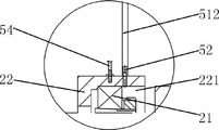
Fig. 2 is an enlarged view of fig. 1 at a.
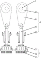
FIG. 3 is a schematic view of the connection and cooperation between two drive shaft assemblies and two lancet assemblies in the lancing mechanism of FIG. 1.
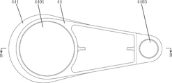
FIG. 4 is a schematic diagram of the structure of the rocker arm of the lancing mechanism of FIG. 1.
Fig. 5 is a sectional view B-B of fig. 4.
FIG. 6 is a logic block diagram of an automatic lubrication system in the lancing mechanism of FIG. 1.
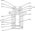
Fig. 7 is a schematic structural view of a guide sleeve in the needling mechanism shown in fig. 1.
Fig. 8 is a schematic view of the fit between the guide sleeve and the push rod shown in fig. 7.
FIG. 9 is a schematic view of the transmission mechanism of the lancing mechanism of FIG. 1.
Fig. 10 is a cross-sectional view C-C of fig. 9.
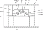
FIG. 11 is a schematic view of the gearbox of the transmission of FIG. 9.
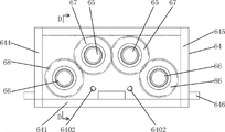
Fig. 12 is a top view of fig. 11.
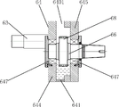
Fig. 13 is a cross-sectional view taken along line D-D of fig. 11.
Detailed Description
As shown in figures 1-6, the needling mechanism of the needle machine comprises a transmission case 1, two transmission shaft assemblies 2 arranged side by side at the left and the right, and two needle assemblies 3 arranged side by side at the left and the right, wherein the transmission shaft assemblies 2 are rotatably arranged in the transmission case 1 through a plurality of transmission bearings 21 and are in a front-back direction; the two pricking pin assemblies 3 correspond to the two transmission shaft assemblies 2 one by one, and the transmission shaft assemblies 2 are connected with the pricking pin assemblies 3 through a plurality of lifting transmission mechanisms 4; the lifting transmission mechanism 4 comprises an eccentric wheel 41, a guide sleeve 42, a push rod 43 and a rocker arm 44, a first mounting hole 4401 which runs forward and backward is formed in the first end of the rocker arm 44, the eccentric wheel 41 is fixedly mounted on the transmission shaft assembly 2, the eccentric wheel 41 is sleeved in the first mounting hole 4401 through an eccentric wheel bearing 411, the guide sleeve 42 is fixedly mounted on the transmission box 1 and runs up and down, the push rod 43 is located in the guide sleeve 42, the first end of the push rod 43 is hinged with the second end of the rocker arm 44, the second end of the push rod 43 is connected with the puncture needle assembly 3, and the rocker arm 44 is made of 7075 aluminum alloy; a plurality of ribs 441 are sequentially arranged from front to back on the first end of the swing arm 44, and each rib 441 extends along the outer circumferential direction of the first mounting hole 4401, and the height of the rib 441 is 30mm.
Among the above-mentioned acupuncture mechanism, the material of rocking arm 44 is the 7075 aluminum alloy of light, and through set up a plurality of strengthening ribs 441 that arrange in proper order from front to back on rocking arm 44 first end, each strengthening rib 441 extends and strengthening rib 441's height value is more than 20 mm along the peripheral direction of first mounting hole 4401, can effectively reduce the wall thickness of first mounting hole 4401 under the condition that does not influence rocking arm 44 structural strength, can effectively improve holistic structural strength and the stability of rocking arm 44 and reduce rocking arm 44's whole weight, and these strengthening ribs 441 can also play the effect of fin, make rocking arm 44 have good radiating effect, make rocking arm 44 non-deformable, be favorable to lifting transmission mechanism 4 can keep steady operation when carrying out high-speed acupuncture, thereby be favorable to the improvement of acupuncture frequency.
In this embodiment, two annular mounting grooves 4402 are symmetrically disposed in front and back of the inner wall of the first mounting hole 4401, retaining rings (not shown in the drawings) are mounted in the annular mounting grooves 4402, the outer ring of the eccentric wheel bearing 411 is sleeved in the first mounting hole 4401 and located between the two retaining rings, and the eccentric wheel 41 is sleeved in the inner ring of the eccentric wheel bearing 411. With the structure, the eccentric wheel bearing 411 in the first mounting hole 4401 can be limited by the two retainer rings, so that the position of the eccentric wheel bearing is stable; and can make the overall structure front and back symmetry of first mounting hole 4401, make rocking arm 44 front and back structure symmetry simultaneously having reduced the processing degree of difficulty of first mounting hole 4401, effectively prevent that the skew from appearing in the focus of rocking arm 44 for the operation of rocking arm 44 is more steady, is favorable to the improvement of acupuncture frequency.
In this embodiment, a first end of the push rod 43 is hinged to a second end of the rocker arm 44 through a push rod pin 45 extending forward and backward; the second end of the rocker arm 44 is provided with two connecting arms 442 arranged side by side in the front and back direction, the connecting arms 442 are provided with second mounting holes 4403 running in the front and back direction, and the two second mounting holes 4403 are respectively provided with the push rod bearings 46; the first end of the push rod 43 is arranged between the two connecting arms 442, the first end of the push rod 43 is provided with a third mounting hole 431, and the third mounting hole 431 corresponds to the two second mounting holes 4403; the pushrod pin 45 is located in the third mounting hole 431 and the inner race of the two pushrod bearings 46. By adopting the structure, the hinge joint between the first end of the push rod 43 and the second end of the rocker arm 44 can be realized through the matching between the push rod pin shaft 45 and the two push rod bearings 46, and the integral structure of the rocker arm 44 is symmetrical front and back, so that the gravity center of the rocker arm 44 is effectively prevented from being deviated, the operation of the rocker arm 44 is more stable, and the improvement of the acupuncture frequency is facilitated.
In the present embodiment, the needle assembly 3 includes a needle beam 31, a needle plate 32 and a plurality of needles 33, the needle plate 32 is fixedly mounted on the needle beam 31, the needles 33 are arranged on the needle plate 32 (the needles 33 are usually uniformly distributed on the needle plate 32), wherein the needle beam 31 is connected with a push rod 43; the needle beam 31 is made of aluminum alloy or magnesium alloy. Thus, the overall weight of the lifting transmission mechanism 4 can be further reduced, and the lifting transmission mechanism 4 can be kept in stable operation when high-speed needling is carried out.
The needling mechanism further comprises an automatic lubricating system 5, the automatic lubricating system 5 further comprises an oil tank (not shown in the figure), an oil transfer pump 51, a plurality of oil supply joints 52 for supplying lubricating oil to each transmission bearing 21, a PLC 53 and a plurality of temperature sensors 54 for detecting the temperature of each transmission bearing 21, an oil inlet of the oil transfer pump 51 is communicated with a cavity of the oil tank through a first oil transfer pipe 511, inlets of the oil supply joints 52 are respectively communicated with an oil outlet of the oil transfer pump 51 through a second oil transfer pipe 512, and the second oil transfer pipe 512 is provided with an electromagnetic switch valve 513; the temperature sensors 54 are electrically connected to respective input ends of the PLC controller 53, and the oil feed pump 51 and the electromagnetic switch valves 513 are electrically connected to respective output ends of the PLC controller 53.
The acupuncture mechanism of the embodiment further comprises a plurality of bearing seats 22, and each bearing seat 22 is fixedly installed in the transmission case 1 and is sequentially arranged along the axial direction of the transmission shaft assembly 2; the number of the bearing blocks 22 is the same as that of the transmission bearings 21, the bearing blocks 22 correspond to one another, mounting grooves 221 are formed in the bearing blocks 22, and the transmission bearings 21 are mounted in the mounting grooves 221 of the bearing blocks 22; the temperature sensors 54 and the oil supply connectors 52 are the same in number and correspond to the bearing seats 22 one by one, the temperature sensors 54 and the oil supply connectors 52 are both installed on the wall of the installation groove 221 and correspond to the position of the transmission bearing 21, and the outlet of the oil supply connector 52 is located on the inner side of the installation groove 221. During the operation of the needling machine, the lubricating oil flows into the mounting groove 221 of the bearing seat 22 through the outlet of the oil supply joint 52 and lubricates the transmission bearing 21 in the mounting groove 221; because the transmission bearing 21 and the bearing seat 22 are both made of metal materials and have good thermal conductivity, the PLC controller 53 can detect the temperature value of the bearing seat 22 through the temperature sensor 54 to obtain the corresponding actual temperature value of the transmission bearing 21, and then control the opening duration of the corresponding electromagnetic switch valve 513 accordingly.
In this embodiment, the automatic lubrication system 5 further includes a human-machine interface 55, and the human-machine interface 55 is connected to corresponding input and output terminals of the PLC controller 53.
Referring to fig. 7 and 8, the guide sleeve 42 includes an outer guide sleeve seat 421 and an inner guide sleeve 422, the outer guide sleeve seat 421 is fixedly installed on the transmission case 1, the outer guide sleeve seat 421 has an installation cavity 4211 with an upper opening and a lower opening therein, the inner guide sleeve 422 is disposed in the installation cavity 4211 of the outer guide sleeve seat 421, an outer wall of the inner guide sleeve 422 is fixedly connected with an inner wall of the outer guide sleeve seat 421, and the inner guide sleeve 422 has a guide hole 4221 with a vertical direction therein; the push rod 43 is positioned in the guide hole 4221 of the inner guide sleeve 422, an oil storage gap 4201 is formed between the outer wall of the push rod 43 and the inner wall of the guide hole 4221, and the lower end of the outer guide sleeve seat 421 is provided with an oil seal cover 423 (the oil seal cover 423 is used for sealing the lower end of the oil storage gap 4201, so that lubricating oil cannot leak from the lower end of the outer guide sleeve seat 421); an oil storage groove 4222 is formed in the inner wall of the upper portion of the guide hole 4221, an annular groove 4223 extending along the circumferential direction of the guide hole 4221 is formed in the inner wall of the middle of the guide hole 4221 (an annular oil storage cavity 4202 for storing lubricating oil is formed between the outer wall of the push rod 43 and the inner wall of the annular groove 4223); an opening at the upper end of the guide hole 4221 is communicated with the bottom of a cavity of the transmission case 1, an oil return port 4212 is arranged on the side wall of the outer guide sleeve seat 421, the oil return port 4212 is communicated with the lower end of the oil storage gap 4201, the oil return port 4212 is communicated with the cavity of the oil tank through an oil return pipe (not shown in the figure), and an oil return pump (not shown in the figure) is arranged on the oil return pipe.
In this embodiment, the guide hole 4221 is a circular through hole, the ring groove 4223 is a circular ring groove, and the center line of the ring groove 4223 coincides with the center line of the guide hole 4221.
In this embodiment, the upper end of the guide hole 4221 of the inner guide sleeve 422 has a circular truncated cone-shaped opening with a large upper part and a small lower part, a gap between the top of the inner wall of the circular truncated cone-shaped opening and the push rod 43 forms an oil inlet 4203, and the oil inlet 4203 is communicated with the upper end of the oil storage groove 4222; the oil storage tank 4222 comprises a left-handed spiral groove 42221 and a right-handed spiral groove 42222, the left-handed spiral groove 42221 and the right-handed spiral groove are interwoven into a net, the upper end of the left-handed spiral groove 42221 and the upper end of the right-handed spiral groove are communicated with the oil inlet 4203, and the lower end of the left-handed spiral groove 42221 and the lower end of the right-handed spiral groove 42222 are communicated with the annular groove 4223. With such a structure, lubricating oil can smoothly enter the left-handed spiral groove 42221 and the right-handed spiral groove 42222 through the oil inlet 4203 and flow from top to bottom, and is uniformly dispersed on the inner wall of the upper part of the guide hole 4221, so that a lubricating oil layer is formed between the inner wall of the guide hole 4221 and the outer wall of the push rod 43 and is filled into the annular oil storage cavity 4202.
In this embodiment, an upper annular positioning groove 4213, a lower annular positioning groove 4214 and a spiral positioning groove 4215 are disposed on an inner wall of the outer guide sleeve seat 421, the spiral positioning groove 4215 is located between the upper annular positioning groove 4213 and the lower annular positioning groove 4214, an upper end of the spiral positioning groove 4215 is communicated with the upper annular positioning groove 4213, and a lower end of the spiral positioning groove 4215 is communicated with the lower annular positioning groove 4214; the outer wall of the inner guide sleeve 422 is provided with an upper annular flange 4224, a lower annular flange 4225 and a spiral protruding strip 4226, the upper annular flange 4224 is positioned in the upper annular positioning groove 4213 and is tightly combined with the upper annular positioning groove 4213, the lower annular flange 4225 is positioned in the lower annular positioning groove 4214 and is tightly combined with the lower annular positioning groove 4214, and the spiral protruding strip 4226 is positioned in the spiral positioning groove 4215 and is tightly combined with the spiral positioning groove 4215. The inner guide sleeve 422 is firmly combined to the outer guide sleeve seat 421 through the tight combination between the upper annular flange 4224 and the upper annular positioning groove 4213, between the lower annular flange 4225 and the lower annular positioning groove 4214, and between the spiral protruding strip 4226 and the spiral positioning groove 4215, so that the inner guide sleeve 422 is ensured not to be dislocated in the process that the push rod 43 reciprocates up and down in the inner guide sleeve 422.
In bookIn an embodiment, the outer guide holder 421 is made of cast iron and the inner guide 422 is made of tin-based babbitt. The outer guide sleeve seat 421 can be made of cast iron by a casting process, the inner guide sleeve 422 is formed on the inner side of the outer guide sleeve seat 421 by a casting process of tin-based babbitt alloy, and the guide hole 4221 and the oil storage groove 4222 are processed on the inner guide sleeve 422, so that the inner guide sleeve 422 can be firmly combined on the outer guide sleeve seat 421. The tin-based babbitt alloy can be cast by using a tin-based babbitt alloy ZSnSb 11 Cu 6 Its friction coefficient is 0.005 in the presence of oil and 0.28 in the absence of oil, which can greatly reduce friction force and heat generation.
The following briefly describes the working principle of the automatic lubrication system 5:
in the automatic lubrication system 5, the oil tank is filled with lubricating oil; when the oil delivery pump 51 and each electromagnetic switch valve 513 are in an open state, the lubricating oil in the oil tank flows through the first oil delivery pipe 511, the oil delivery pump 51 and each second oil delivery pipe 512 in sequence under the pumping of the oil delivery pump 51 to enter each oil supply joint 52, and the lubricating oil is supplied to each transmission bearing 21 for lubrication and heat dissipation; the PLC controller 53 detects the actual temperature value of the corresponding drive bearing 21 through each temperature sensor 54, compares the actual temperature value with the upper limit value of the temperature range value set in the PLC controller 53, and according to the comparison result, the PLC controller 53 outputs a control signal to control the oil feed pump 51 and each electromagnetic switch valve 513 to be in an open or closed state, thereby controlling the oil feed amount to each drive bearing 21, so that each drive bearing 21 maintains the optimal lubricating and heat dissipating effects, and thus each drive bearing 21 is within the set temperature range value.
The worker can select the optimal oil supply amount and oil supply time through experiments, and input corresponding working parameters (such as the opening duration of each time of the electromagnetic switch valve 513, the set temperature range value and the like) into the PLC controller 53 through the human-computer interface 55 in advance, and the PLC controller 53 controls the on-off of each electromagnetic switch valve 513 in the working process of the needling machine, so as to achieve the optimal lubricating and heat dissipation effects, and the human-computer interface 55 can display the actual temperature value of each transmission bearing 21 and whether the transmission bearing is in an abnormal state in real time. The temperature range value set in the PLC controller 53 is set by referring to the requirement that the temperature rise range of the driving bearing 21 is not more than 30 ℃ (that is, the temperature of the driving bearing 21 is at most 30 ℃ higher than the ambient temperature) and the maximum temperature of the driving bearing 21 itself is not more than 80 ℃ when the driving bearing 21 is normally operated, and for example, in the case where the ambient temperature is 30 ℃, the temperature range value may be set to 30 ℃ to 60 ℃ and the upper limit value of the temperature range value is 60 ℃.
During the operation of the needling machine, the PLC controller 53 keeps the oil transfer pump 51 in an open state, and controls each electromagnetic switch valve 513 to open for a certain period of time and then close: when each electromagnetic switch valve 513 is in an open state, the lubricating oil in the oil tank flows through the first oil delivery pipe 511, the oil delivery pump 51 and each second oil delivery pipe 512 in sequence under the pumping action of the oil delivery pump 51 to enter each oil supply joint 52, and the lubricating oil is quantitatively supplied to the corresponding transmission bearing 21 by each oil supply joint 52; when each electromagnetic switch valve 513 is in a closed state, each oil supply joint 52 stops supplying the lubricating oil to the corresponding transmission bearing 21, so that the lubricating oil is regularly and quantitatively supplied to each transmission bearing 21, each transmission bearing 21 is in a set temperature range value, and each transmission bearing 21 keeps the optimal lubricating and heat dissipation effects. If the temperature of the transmission bearing 21 rises abnormally (i.e. the actual temperature value is detected to exceed the upper limit value of the set temperature range value), the PLC controller 53 controls the electromagnetic switch valve 513 on the second oil delivery pipe 512 corresponding to the transmission bearing 21 to be in a continuously opened state, and simultaneously makes the human-computer interface 55 give an alarm (which can give an alarm in the forms of flashing, sound, etc. to alert the worker), and alerts the worker that the temperature of the transmission bearing 21 rises abnormally; subsequently, if the temperature sensor 54 detects that the temperature of the transmission bearing 21 returns to the set temperature range value, the PLC controller 53 controls the corresponding electromagnetic switch valve 513 to close, and the human-machine interface 55 stops alarming; if the temperature sensor 54 detects that the temperature of the drive bearing 21 does not drop (the temperature remains unchanged or rises), it indicates that the drive bearing 21 is damaged, and the PLC controller 53 will continuously alarm through the human-computer interface 55, so as to remind the maintenance personnel to handle in time, wait for abnormal removal, and avoid larger damage.
In the working process of the needle machine, redundant lubricating oil lubricated by each transmission bearing 21 can drop to the bottom of the cavity of the transmission case 1 and be stored (the oil level of the lubricating oil in the transmission case 1 is generally slightly higher than the upper end opening of the guide hole 4221), the lubricating oil in the transmission case 1 can enter the oil storage groove 4222 from the upper end opening of the guide hole 4221 and be refilled into the annular oil storage cavity 4202 and the oil storage gap 4201 below the annular oil storage cavity 4202, a lubricating oil layer is formed between the inner wall of the guide hole 4221 and the outer wall of the push rod 43, and the lubricating oil flowing out from the oil return port 4212 returns to the oil tank through an oil return pipe, so that the purposes of recycling and cooling the lubricating oil are achieved; the contact area between the push rod 43 and the inner guide sleeve 422 can be reduced by arranging the annular groove 4223, so that the friction force between the push rod 43 and the inner guide sleeve 422 is reduced, the heat productivity generated by friction in the process that the push rod 43 reciprocates up and down in the inner guide sleeve 422 can be effectively reduced, and the frequency of the up-and-down reciprocating motion of the push rod 43 can be increased. In the process that the push rod 43 moves downwards along the guide hole 4221 of the inner guide sleeve 422, the annular step at the joint of the lower side groove wall of the annular groove 4223 and the lower inner wall of the guide hole 4221 forms an oil baffle ring, so that a large amount of lubricating oil driven by the push rod 43 can be blocked, most of the lubricating oil is left in the annular oil storage cavity 4202, and only a small amount of lubricating oil is filled in the oil storage gap 4201 below the annular oil storage cavity 4202, so that the situation that oil leakage occurs due to the fact that the excessive lubricating oil is brought to the oil seal by the push rod 43 is avoided, the lubricating oil is effectively prevented from polluting the needle plate 32 and a non-woven product, normal production of the needling mechanism is not greatly influenced, and due to the fact that shutdown is not needed for maintenance, the production efficiency of the needling machine can be improved, and the maintenance cost of the needling machine can be reduced.
Referring to fig. 9-13, the above-mentioned acupuncture mechanism further includes a transmission device 6, the transmission device 6 includes a power input shaft 63, a gear box 64, two upper rotating shafts 65, two lower rotating shafts 66, two upper gears 67 and two lower gears 68; the power input shaft 63 is rotatably arranged in the transmission case 1 and is in a front-back direction, and the power input shaft 63 is positioned in front of the two transmission shaft assemblies 2; the gear box 64 is detachably arranged in the transmission box 1 and is positioned between the power input shaft 63 and the two transmission shaft assemblies 2, the two upper rotating shafts 65 and the two lower rotating shafts 66 can be rotatably arranged in the gear box 64 and move forwards and backwards, the two upper rotating shafts 65 are arranged side by side left and right, the front end of one upper rotating shaft 65 is detachably connected with the rear end of the power input shaft 63, and the axes of the two upper rotating shafts 65 and the rear end of the power input shaft 63 are coincident; the two lower rotating shafts 66 are arranged on two sides of the two upper rotating shafts 65 side by side left and right, the height positions of the lower rotating shafts 66 are lower than that of the upper rotating shafts 65, the two lower rotating shafts 66 correspond to the two transmission shaft assemblies 2 one by one, the rear ends of the lower rotating shafts 66 are detachably connected with the front ends of the corresponding transmission shaft assemblies 2, and the axes of the lower rotating shafts and the front ends of the corresponding transmission shaft assemblies 2 are coincident; the two upper gears 67 correspond to the two upper rotating shafts 65 one by one, and the two upper gears 67 are respectively installed on the corresponding upper rotating shafts 65 and are meshed with each other; two lower gears 68 are in one-to-one correspondence with the two lower rotating shafts 66, the two lower gears 68 are respectively mounted on the corresponding lower rotating shafts 66, the lower gear 68 on the left side is meshed with the upper gear 67 on the left side, and the lower gear 68 on the right side is meshed with the upper gear 67 on the right side.
In the present embodiment, both the upper gear 67 and the lower gear 68 are helical gears. The bevel gear has the characteristics of stable transmission, small impact, vibration and noise and the like, so the bevel gear is widely used in high-speed and heavy-load occasions and is suitable for the more precise production process in the field of acupuncture. The upper gear 67 and the lower gear 68 can adopt helical gears with the same specification and size (the reference circle diameter is 138 mm, and the excircle diameter is 146 mm).
In the present embodiment, the rear end of the lower shaft 66 is connected to the front end of the propeller shaft assembly 2 via a coupling freewheel 69. The coupling flywheel 69 is a disc-shaped member with a large moment of inertia and functions to store energy to increase the moment of inertia and to make the drive shaft assembly 2 rotate more smoothly.
An opening 6401 is formed in the top of the gear box 64, a plurality of oil discharge holes 6402 in the same height position are formed in the bottom of a side plate of the gear box 64, and lubricating oil is filled in the bottom of an inner cavity of the gear box 64; the upper rotating shaft 65 is mounted in the gear case 64 by two upper bearings (not shown), the lower rotating shaft 66 is mounted in the gear case 64 by two lower bearings 647, and the lower portions of the lower gear 68 and the lower bearings 647 are immersed in the lubricating oil.
In this embodiment, the gear box 64 includes a bottom plate 641, a front side plate 642, a rear side plate 643, a left side plate 644, and a right side plate 645, wherein lower edges of the front side plate 642, the rear side plate 643, the left side plate 644, and the right side plate 645 are respectively connected to corresponding edges of the bottom plate 641, and upper edges of the front side plate 642, the rear side plate 643, the left side plate 644, and the right side plate 645 jointly enclose an opening 6401; the oil drain hole 6402 is provided in the front plate 642 or the rear plate 643; both ends of the upper rotating shaft 65 are mounted on the front side plate 642 and the rear side plate 643 respectively through two upper bearings, and both ends of the lower rotating shaft 66 are mounted on the front side plate 642 and the rear side plate 643 respectively through two lower bearings 647.
In this embodiment, a fixing seat 646 is disposed on an outer side wall of the gear box 64, the fixing seat 646 is provided with a plurality of fixing through holes 6461 extending up and down, and each fixing through hole 6461 is provided with a fixing bolt (not shown in the figure); the top of the transmission case 1 is provided with a mounting port 101, and a plurality of fixing screw holes (not shown in the figure) for mounting each fixing bolt are arranged at corresponding positions inside the transmission case 1.
The following brief description of the installation method and the working principle of the transmission device 6 is as follows:
when the installation is carried out, the two upper gears 67 are respectively installed on the corresponding upper rotating shafts 65, the two lower gears 68 are respectively installed on the corresponding lower rotating shafts 66, and then the two upper rotating shafts 65 and the two lower rotating shafts 66 are installed in the gear box 64; then, the gear box 64 is placed into the transmission case 1 from the mounting opening 101 in a hoisting mode, the front end of one upper rotating shaft 65 is connected with the rear end of the power input shaft 63, the axes of the upper rotating shaft and the power input shaft coincide, and the rear ends of two lower rotating shafts 66 are respectively connected with the front ends of the corresponding transmission shaft assemblies 2, and the axes of the two lower rotating shafts coincide; after the positions of the upper rotating shaft 65 and the lower rotating shaft 66 and the positions of the respective fixing bolts and the respective fixing screw holes are aligned, the screw rods of the respective fixing bolts are screwed into the respective fixing screw holes, so that the gear case 64 is fixedly installed in the transmission case 1. The clearance and the center distance between the two upper gears 67 and the two lower gears 68 are ensured by the gear box 64, the gear box 64 is formed by the precision machining of a numerical control machine, and the precision is ensured, so that the assembly precision is high, the stability of the assembly effect can be effectively improved, and the two lower rotating shafts 66 are ensured to be respectively accurately aligned with the corresponding transmission shaft assemblies 2, so that the meshing transmission between the gears is stable, the debugging time is saved, and the assembly efficiency is improved. In addition, since the transmission between the two transmission shaft assemblies 2 is realized by the engagement between the two upper gears 67 and the two lower gears 68, the transmission device 6 can adopt a gear with a smaller diameter to transmit instead of a gear with a large diameter, and the high-speed gear is converted into a medium-speed gear, so that the torque and the strength of the gear can be improved.
The front end of the power input shaft 63 is connected with the needling driving device in a transmission way. When the fiber web needling machine works, the power input shaft 63 rotates under the driving of the driving device to drive the corresponding upper rotating shaft 65 to rotate, then the other upper rotating shaft 65 is driven to rotate through the meshing transmission between the two upper gears 67, and the two lower rotating shafts 66 are driven to rotate relatively through the meshing transmission between the corresponding upper gear 67 and the lower gear 68, so that the two transmission shaft assemblies 2 are driven to rotate relatively, then the lifting transmission mechanisms 4 drive the felting needles 33 to do reciprocating linear motion, so that the fiber web is repeatedly needled, and the fluffy fiber web is consolidated through the needling effect. During operation, the lubricant in the lubricant storage container can be added into the gear box 64 through the opening 6401 at the top of the gear box 64, and the lubricant can flow through between the two upper gears 67, lubricate the two upper gears 67 and the two upper bearings, and finally be stored at the bottom of the cavity of the gear box 64; when the oil level of the lubricating oil in the gear box 64 is higher than the position of the oil discharge hole 6402, the redundant lubricating oil flows into the lubricating oil storage container through the oil discharge hole 6402 (the lubricating oil in the lubricating oil storage container can be conveyed to the position above the gap between the two upper gears 67 through the oil pump and the oil conveying pipe to realize the circulation flow of the lubricating oil), so that the oil level height of the lubricating oil in the gear box 64 is controlled; and through making two lower gears 68, the lower part of two lower bearing 647 all soak in lubricating oil, both guaranteed the lubrication, obtain good heat dissipation again, through the oil level height of the lubricating oil in the control gear box 64, also guaranteed that lubricating oil will not be too big to lower gear 68's resistance, ensure that the transmission is more steady.
Furthermore, it should be noted that the names of the parts of the embodiments described in the present specification may be different, and the equivalent or simple changes of the structures, the features and the principles described in the present patent concept are included in the protection scope of the present patent. Various modifications, additions and substitutions for the specific embodiments described may be made by those skilled in the art without departing from the scope of the invention as defined in the accompanying claims.
Claims (9)
1. A needling mechanism of a needling machine comprises a transmission case, at least one transmission shaft component and at least one pricking pin component, wherein the transmission shaft component is rotatably arranged in the transmission case through a plurality of transmission bearings and is in a front-back direction; the felting needle subassembly is the same and the one-to-one with the quantity of transmission shaft subassembly, the transmission shaft subassembly is connected with the felting needle subassembly through a plurality of lifting drive mechanisms, lifting drive mechanism includes the eccentric wheel, the guide pin bushing, push rod and rocking arm, the first end of rocking arm is equipped with the first mounting hole of trend around the trend, eccentric wheel fixed mounting is on the transmission shaft subassembly, and the eccentric wheel cup joints in first mounting hole through eccentric wheel bearing, guide pin bushing fixed mounting is on the transmission case and for trend from top to bottom, the push rod is in the guide pin bushing, the first end of push rod is articulated with the second end of rocking arm, the second end of push rod is connected with the felting needle subassembly, its characterized in that: the rocker arm is made of aluminum alloy or magnesium alloy; a plurality of reinforcing ribs are sequentially arranged at the first end of the rocker arm from front to back, each reinforcing rib extends along the outer periphery of the first mounting hole, and the height value of each reinforcing rib is more than 20 mm; the needling mechanism further comprises an automatic lubricating system, the automatic lubricating system further comprises an oil tank, an oil delivery pump, a plurality of oil supply joints for supplying lubricating oil to each transmission bearing, a control device and a plurality of temperature sensors for detecting the temperature of each transmission bearing, an oil inlet of the oil delivery pump is communicated with the cavity of the oil tank through a first oil delivery pipe, an inlet of each oil supply joint is communicated with an oil outlet of the oil delivery pump through a second oil delivery pipe respectively, and the second oil delivery pipe is provided with an electromagnetic switch valve; each temperature sensor is electrically connected with the corresponding input end of the control device, and the oil transfer pump and each electromagnetic switch valve are electrically connected with the corresponding output end of the control device.
2. The needling mechanism of a needling machine according to claim 1, characterized in that: the aluminum alloy used for manufacturing the rocker arm is 7075 aluminum alloy; the height value of the reinforcing rib is 30mm.
3. The needling mechanism of a needling machine according to claim 1, characterized in that: the inner wall of the first mounting hole is provided with two annular mounting grooves which are symmetrically arranged front and back, retainer rings are mounted in the annular mounting grooves, the outer ring of the eccentric wheel bearing is sleeved in the first mounting hole and positioned between the two retainer rings, and the eccentric wheel is sleeved in the inner ring of the eccentric wheel bearing; the first end of the push rod is hinged with the second end of the rocker arm through a push rod pin shaft in the front-back direction; the second end of the rocker arm is provided with two connecting arms which are arranged side by side in the front and back direction, the connecting arms are provided with second mounting holes in the front and back direction, and the two second mounting holes are respectively provided with a push rod bearing; the first end of the push rod is arranged between the two connecting arms, the first end of the push rod is provided with a third mounting hole, and the third mounting hole corresponds to the two second mounting holes in position; the push rod pin shaft is positioned in the third mounting hole and the inner rings of the two push rod bearings.
4. The needling mechanism of a needle loom as claimed in claim 1, wherein: the needling mechanism comprises two transmission shaft assemblies arranged side by side left and right and two pricking pin assemblies arranged side by side left and right, the two pricking pin assemblies correspond to the two transmission shaft assemblies one by one, and the transmission shaft assemblies are connected with the pricking pin assemblies through a plurality of lifting transmission mechanisms; the needling mechanism further comprises a transmission device, wherein the transmission device comprises a power input shaft, a gear box, two upper rotating shafts, two lower rotating shafts, two upper gears and two lower gears; the power input shaft is rotatably arranged in the transmission case and moves forwards and backwards, and is positioned in front of the two transmission shaft assemblies; the gearbox is detachably arranged in the transmission case and is positioned between the power input shaft and the two transmission shaft assemblies, the two upper rotating shafts and the two lower rotating shafts are rotatably arranged in the gearbox and move forward and backward, the two upper rotating shafts are arranged side by side left and right, the front end of one upper rotating shaft is detachably connected with the rear end of the power input shaft, and the axes of the two upper rotating shafts and the rear end of the power input shaft are coincident; the two lower rotating shafts are arranged on the two sides of the two upper rotating shafts side by side from left to right, the height positions of the lower rotating shafts are lower than that of the upper rotating shafts, the two lower rotating shafts correspond to the two transmission shaft assemblies one by one, the rear ends of the lower rotating shafts are detachably connected with the front ends of the corresponding transmission shaft assemblies, and the axes of the lower rotating shafts and the front ends of the corresponding transmission shaft assemblies are coincident; the two upper gears correspond to the two upper rotating shafts one by one, and the two upper gears are respectively arranged on the corresponding upper rotating shafts and are meshed with each other; the two lower gears correspond to the two lower rotating shafts one by one, the two lower gears are respectively installed on the corresponding lower rotating shafts, the lower gear on the left side is meshed with the upper gear on the left side, and the lower gear on the right side is meshed with the upper gear on the right side.
5. The needling mechanism of a needling machine according to claim 4, wherein: the top of the gear box is provided with an opening, the bottom of a side plate of the gear box is provided with at least one oil discharge hole, and lubricating oil is arranged in the bottom of an inner cavity of the gear box; the upper rotating shaft is arranged in the gear box through two upper bearings, the lower rotating shaft is arranged in the gear box through two lower bearings, and the lower parts of the lower gear and the lower bearings are immersed in lubricating oil; the upper gear and the lower gear are both helical gears.
6. The needling mechanism of a needling machine according to any one of claims 1 to 5, characterized in that: the needling mechanism further comprises a plurality of bearing seats, and each bearing seat is fixedly installed in the transmission case and sequentially arranged along the axial direction of the transmission shaft assembly; the bearing seats are the same in number and correspond to the transmission bearings one by one, mounting grooves are formed in the bearing seats, and the transmission bearings are mounted in the mounting grooves of the bearing seats; the temperature sensor, the oil supply connector and the bearing seat are the same in number and correspond to each other one by one, the temperature sensor and the oil supply connector are both installed on the groove wall of the installation groove and correspond to the position of the transmission bearing, and the outlet of the oil supply connector is located on the inner side of the installation groove.
7. The needling mechanism of a needle loom according to any one of claims 1 to 5, wherein: the guide sleeve comprises an outer guide sleeve seat and an inner guide sleeve, the outer guide sleeve seat is fixedly arranged on the transmission box, an installation cavity with an upper opening and a lower opening is formed in the outer guide sleeve seat, the inner guide sleeve is arranged in the installation cavity of the outer guide sleeve seat, the outer wall of the inner guide sleeve is fixedly connected with the inner wall of the outer guide sleeve seat, and a guide hole in the vertical direction is formed in the inner guide sleeve; the push rod is arranged in a guide hole of the inner guide sleeve, an oil storage gap is formed between the outer wall of the push rod and the inner wall of the guide hole, and an oil seal cover is arranged at the lower end of the outer guide sleeve seat; an oil storage tank is arranged on the inner wall of the upper part of the guide hole, and an annular groove extending along the circumferential direction of the inner wall of the middle part of the guide hole is arranged on the inner wall of the middle part of the guide hole; the upper end opening of guiding hole and the cavity bottom intercommunication of transmission case are equipped with the oil return opening on the outer guide sleeve seat lateral wall, oil return opening and the intercommunication of oil storage clearance lower extreme, the oil return opening through the oil return pipe with the cavity intercommunication of oil tank installs the scavenge pump on the oil return pipe.
8. The needling mechanism of a needling machine according to claim 7, characterized in that: the upper end of the guide hole of the inner guide sleeve is provided with a circular truncated cone-shaped opening with a large upper part and a small lower part, a gap between the top of the inner wall of the circular truncated cone-shaped opening and the push rod forms an oil inlet, and the oil inlet is communicated with the upper end of the oil storage tank; the oil storage tank comprises a left-handed spiral groove and a right-handed spiral groove, the left-handed spiral groove and the right-handed spiral groove are interwoven into a net, the upper end of the left-handed spiral groove and the upper end of the right-handed spiral groove are communicated with the oil inlet, and the lower end of the left-handed spiral groove and the lower end of the right-handed spiral groove are communicated with the annular groove.
9. The needling mechanism of a needling machine according to claim 7, characterized in that: the inner wall of the outer guide sleeve seat is provided with an upper annular positioning groove and a lower annular positioning groove, the outer wall of the inner guide sleeve is provided with an upper annular convex edge and a lower annular convex edge, the upper annular convex edge is positioned in the upper annular positioning groove and is tightly combined with the upper annular positioning groove, and the lower annular convex edge is positioned in the lower annular positioning groove and is tightly combined with the lower annular positioning groove; the inner wall of the outer guide sleeve seat is provided with a spiral positioning groove, and the spiral positioning groove is positioned between the upper annular positioning groove and the lower annular positioning groove; the outer wall of the inner guide sleeve is provided with a spiral raised line which is positioned in the spiral positioning groove and is tightly combined with the spiral positioning groove; the outer guide sleeve seat is made of cast iron, and the inner guide sleeve is made of tin-based Babbitt alloy.
Priority Applications (1)
| Application Number | Priority Date | Filing Date | Title |
|---|---|---|---|
| CN202111056448.1A CN113774565B (en) | 2021-09-09 | 2021-09-09 | Needling mechanism of needling machine |
Applications Claiming Priority (1)
| Application Number | Priority Date | Filing Date | Title |
|---|---|---|---|
| CN202111056448.1A CN113774565B (en) | 2021-09-09 | 2021-09-09 | Needling mechanism of needling machine |
Publications (2)
| Publication Number | Publication Date |
|---|---|
| CN113774565A CN113774565A (en) | 2021-12-10 |
| CN113774565B true CN113774565B (en) | 2022-11-04 |
Family
ID=78842082
Family Applications (1)
| Application Number | Title | Priority Date | Filing Date |
|---|---|---|---|
| CN202111056448.1A Active CN113774565B (en) | 2021-09-09 | 2021-09-09 | Needling mechanism of needling machine |
Country Status (1)
| Country | Link |
|---|---|
| CN (1) | CN113774565B (en) |
Families Citing this family (1)
| Publication number | Priority date | Publication date | Assignee | Title |
|---|---|---|---|---|
| CN118385220B (en) * | 2024-06-26 | 2024-08-16 | 广州三荣包装材料有限公司 | Full-automatic dust remover |
Family Cites Families (12)
| Publication number | Priority date | Publication date | Assignee | Title |
|---|---|---|---|---|
| JP2000074193A (en) * | 1998-08-26 | 2000-03-07 | Nissan Motor Co Ltd | V-belt type continuously variable transmission lubrication system |
| CN2542697Y (en) * | 2002-03-21 | 2003-04-02 | 王卫成 | Guide case lubricating mechanism of needling machine |
| WO2009019111A1 (en) * | 2007-08-04 | 2009-02-12 | Oerlikon Textile Gmbh & Co. Kg | Device for needling a fibrous web |
| CN201520873U (en) * | 2009-10-22 | 2010-07-07 | 江苏省仪征市海润纺织机械有限公司 | Single-unit main spindle box of high-speed needling machine |
| CN205133937U (en) * | 2015-11-05 | 2016-04-06 | 汕头三辉无纺机械厂有限公司 | Acupuncture mechanism of needle loom |
| CN206219774U (en) * | 2016-11-03 | 2017-06-06 | 汕头三辉无纺机械厂有限公司 | The acupuncture mechanism of single main shaft single needle area needing machine |
| CN207331213U (en) * | 2017-09-27 | 2018-05-08 | 汕头三辉无纺机械厂有限公司 | The push rod guide sleeve seat of needing machine |
| CN108035078B (en) * | 2017-11-08 | 2020-06-16 | 四川环龙技术织物有限公司 | Method for connecting transmission main shaft of papermaking felt needling machine |
| CN107881654A (en) * | 2017-12-12 | 2018-04-06 | 常熟市振泰无纺机械有限公司 | The needing machine of large tank structure |
| CN212955619U (en) * | 2020-08-13 | 2021-04-13 | 广东三辉无纺机械有限公司 | Through-shaft type double-needle-plate needling mechanism |
| CN211897308U (en) * | 2020-08-13 | 2020-11-10 | 广东三辉无纺机械有限公司 | Through-shaft type single-needle-plate needling mechanism |
| CN213599042U (en) * | 2020-10-30 | 2021-07-02 | 扬州华凯机械有限公司 | Lubricating and cooling system of needling machine |
-
2021
- 2021-09-09 CN CN202111056448.1A patent/CN113774565B/en active Active
Also Published As
| Publication number | Publication date |
|---|---|
| CN113774565A (en) | 2021-12-10 |
Similar Documents
| Publication | Publication Date | Title |
|---|---|---|
| CN102182808B (en) | Spindle drive mechanism with lubrication oil area in seal area | |
| CN113774565B (en) | Needling mechanism of needling machine | |
| CN107387735B (en) | Lightweight gearbox body with automatic lubricating oil collection and distribution function | |
| CN218761313U (en) | Speed reducer with oil injection mechanism | |
| CN113701036A (en) | Automatic lubricating system of needling machine | |
| CN203488667U (en) | Lubricant oil way device of bivariate assembly pump driving device | |
| CN113623384A (en) | Oil pumping unit reducer bearing lubricating device capable of adjusting oil supply | |
| CN120487859A (en) | A gear transmission system | |
| CN216556408U (en) | Automatic lubricating system of needling machine | |
| CN218017422U (en) | Cooling, lubricating and circulating system of machine tool | |
| CN113757541B (en) | Through-shaft type single-needle-area double-needle-plate co-position needling machine | |
| CN218863114U (en) | External cooling type dynamic pressure bearing | |
| CN216975732U (en) | Gear box | |
| CN215908366U (en) | Lubricating structure and system sand machine | |
| CN218819562U (en) | Knife rest structure with long-acting lubrication | |
| CN213017623U (en) | Multidirectional lubrication flat grinding type rudder carrier | |
| JP6260425B2 (en) | Outboard motor | |
| CN211082800U (en) | Bearing protection structure and wind power gearbox | |
| CN209385622U (en) | Loading machine gearbox power taking mouth drive shaft spline forced lubrication structure | |
| CN115106823A (en) | Power device of turning, milling and grinding tool rest main shaft | |
| US20250215966A1 (en) | Gearbox | |
| CN213511955U (en) | Dead gear of self-lubricating anti-sticking | |
| CN215445016U (en) | A reducer gear with temperature alarm function | |
| CN221033884U (en) | Gear box for extruder with lubricating structure | |
| CN220488237U (en) | Variable-speed semi-combined gear |
Legal Events
| Date | Code | Title | Description |
|---|---|---|---|
| PB01 | Publication | ||
| PB01 | Publication | ||
| SE01 | Entry into force of request for substantive examination | ||
| SE01 | Entry into force of request for substantive examination | ||
| GR01 | Patent grant | ||
| GR01 | Patent grant | ||
| TR01 | Transfer of patent right |
Effective date of registration: 20230417 Address after: 522000 North of Deshan Street East Section, Industrial Transfer Industrial Park, Jieyang City, Guangdong Province Patentee after: Guangdong Sanhui Nonwoven Machinery Co.,Ltd. Patentee after: Guangdong Sanhui Nonwoven Technology Co.,Ltd. Address before: 522000 north of East section of Deshan street, Jieyang industrial transfer park, Jieyang City, Guangdong Province Patentee before: Guangdong Sanhui Nonwoven Machinery Co.,Ltd. |
|
| TR01 | Transfer of patent right |