CN1137814A - Reflective sheet - Google Patents
Reflective sheet Download PDFInfo
- Publication number
- CN1137814A CN1137814A CN95191100A CN95191100A CN1137814A CN 1137814 A CN1137814 A CN 1137814A CN 95191100 A CN95191100 A CN 95191100A CN 95191100 A CN95191100 A CN 95191100A CN 1137814 A CN1137814 A CN 1137814A
- Authority
- CN
- China
- Prior art keywords
- reflector plate
- face
- cylinder
- reflection
- plane
- Prior art date
- Legal status (The legal status is an assumption and is not a legal conclusion. Google has not performed a legal analysis and makes no representation as to the accuracy of the status listed.)
- Granted
Links
Images


Classifications
-
- E—FIXED CONSTRUCTIONS
- E01—CONSTRUCTION OF ROADS, RAILWAYS, OR BRIDGES
- E01F—ADDITIONAL WORK, SUCH AS EQUIPPING ROADS OR THE CONSTRUCTION OF PLATFORMS, HELICOPTER LANDING STAGES, SIGNS, SNOW FENCES, OR THE LIKE
- E01F9/00—Arrangement of road signs or traffic signals; Arrangements for enforcing caution
-
- G—PHYSICS
- G02—OPTICS
- G02B—OPTICAL ELEMENTS, SYSTEMS OR APPARATUS
- G02B5/00—Optical elements other than lenses
- G02B5/12—Reflex reflectors
- G02B5/122—Reflex reflectors cube corner, trihedral or triple reflector type
- G02B5/124—Reflex reflectors cube corner, trihedral or triple reflector type plural reflecting elements forming part of a unitary plate or sheet
-
- E—FIXED CONSTRUCTIONS
- E01—CONSTRUCTION OF ROADS, RAILWAYS, OR BRIDGES
- E01F—ADDITIONAL WORK, SUCH AS EQUIPPING ROADS OR THE CONSTRUCTION OF PLATFORMS, HELICOPTER LANDING STAGES, SIGNS, SNOW FENCES, OR THE LIKE
- E01F9/00—Arrangement of road signs or traffic signals; Arrangements for enforcing caution
- E01F9/50—Road surface markings; Kerbs or road edgings, specially adapted for alerting road users
- E01F9/506—Road surface markings; Kerbs or road edgings, specially adapted for alerting road users characterised by the road surface marking material, e.g. comprising additives for improving friction or reflectivity; Methods of forming, installing or applying markings in, on or to road surfaces
- E01F9/524—Reflecting elements specially adapted for incorporation in or application to road surface markings
Landscapes
- Physics & Mathematics (AREA)
- Engineering & Computer Science (AREA)
- Architecture (AREA)
- Civil Engineering (AREA)
- Structural Engineering (AREA)
- General Physics & Mathematics (AREA)
- Optics & Photonics (AREA)
- Optical Elements Other Than Lenses (AREA)
- Road Signs Or Road Markings (AREA)
- Illuminated Signs And Luminous Advertising (AREA)
Abstract
A reflecting sheet which comprises a transparent sheet capable of reflection by its reverse, said transparent sheet having the face which is partly or entirely constructed of a plurality of composite surfaces, each being a combination of a cylindrical surface inclined in one direction only and a curved or flat surface inclined in the opposite direction, said composite surfaces being contiguous or intermittent with a flat surface interposed between and being constructed such that a large part of their surface area is accounted for by the cylindrical surfaces, and also having the reverse which is constructed of a plurality of contiguous corner-cube prisms.
Description
This patent relates to a kind of reflector plate and the reflecting plate that is used for road sign, information board and reflector.(in the present invention, noun " reflection " comprises " back reflection ").
Road sign, information board and the reflector of safety and protection usefulness are equipped with reflector plate or reflecting plate (hereinafter being referred to as " reflector plate "), and reflector plate adopts glass strain or right-angle prism as reflector element.The reflection characteristic defectiveness of these reflector elements sees below regrettably.Be used for reflector plate if it is remained untouched, they do not meet industrial standard.
Bead is that they can not realize total reflection as the shortcoming of reflector element, its reason be spherical lens intrinsic spherical aberration.Figure 12 illustrates the incident ray of the bead (3) that focal length equals radius of curvature and the light path of reflected ray.Judge that from focal length all the luminous flux of incident ray should converge at the P point on bead (3) reflecting surface, but in fact, shown in light path figure, because spherical aberration is, situation is really not so.Formed reflection is diffuse reflection, and incident ray is to all direction reflections.This is the low reason of reflected ray brightness that bead sends.Therefore, common reflector plate can not satisfy the requirement to brightness fully.
Right-angle prism is that its high brightness is reflected into the high orientation reflection as the shortcoming of reflector element.Its former because incident ray twice of prism internal reflection and between angle of incidence and the angle of reflection difference very little.In other words, the reflected ray that sends from prism has only when a people present position just can be seen near light source, and the brightness of reflected ray depart from the light source light path in (several years) just very low.In addition, because the brightness of reflected ray is high to the people near light source, thereby make right-angle prism not be suitable for information board.(in other words, adopting the information board of right-angle prism will make us dazzling the eyes) for observer near light source.
Owing to this reason, adopt right-angle prism not meet the industrial standard (as Japanese Industrial Standards) of the brightness of different viewing angles being made regulation, thereby seldom be used for road sign and information board as the reflector plate of reflector element.
Purpose of the present invention is exactly to provide a kind of its catoptrical brightness to be the high reflector plate that also can satisfy various industrial standards fully than common bead reflector plate.
First characteristics of the present invention are as follows: a kind of reflector plate is made of ground, this transparent front portion or entirely be made of the face of cylinder (1) of a plurality of adjacency a slide that can reflect by its back side; The radius of curvature on each face of cylinder is equal or different, and its back side system is by right-angle prism (2) formation of a plurality of adjacency.Only tilt with corresponding each face of cylinder of each right-angle prism plane of incidence (1), shown in Fig. 1~5 in a direction.
Second characteristic of the present invention are as follows: a kind of reflector plate, constitute by (synthetic resin) slide that can reflect by its back side, and the front portion of this slide or whole composite surface by a plurality of adjacency (1) constitute; Each composite surface system only constitutes in the face of cylinder and curved surface or plane (shown in Figure 16~20) in inclination in the other direction that a direction tilts by one, its surface major part that is configured to of above-mentioned composite surface (1) is the face of cylinder, and its back side then is made of the right-angle prism (2) of a plurality of adjacency.
Function of the present invention is as follows:
Reflector plate of the present invention has one as the defined plane of incidence in the claim, and the structure of this plane of incidence makes by the right-angle prism light flux reflected and only propagate on the normal direction of this reflector plate, as Fig. 9 and shown in Figure 10.Reflected ray has sufficient diffusing characteristic diffuser in this narrow light path.The reflection of this kind mode can reduce because the unnecessary loss of the reflected ray that diffuse reflection caused.Thereby might be to the shortcoming of right-angle prism, promptly the requirement (reflecting brightness of predetermined angular) of desirable reflection to satisfy Japanese Industrial Standards and other prescribed by standard corrected and obtained to the highly directive of reflection flux.
The reflection that reflector plate of the present invention produced light path as shown in Figure 15 is indicated.The light that is sent by light source is mapped on the face of cylinder (1), and this face of cylinder is the plane of incidence of reflector plate of the present invention.Incident ray is subjected to entering right-angle prism (2) after the slight refraction at incidence point (j).Incident ray (K) point reflection on first reflecting surface of right-angle prism (2) afterwards, (1) point reflection on second reflecting surface of this right-angle prism (2) is last again, (m) of (1) some refraction on the face of cylinder.Angle of reflection is different with angle of incidence as a result, thereby produces diffuse effect.
The difference of angle of incidence and angle of reflection is by the slope differences decision of (m) on the face of cylinder that slope and reflected ray passed through (1) of the incidence point (j) on the face of cylinder (1) point.Above-mentioned differential seat angle can draw by the equation below incidence point among Figure 14 (j) and refraction point (m) application,
n×sini=n’×sini’
Wherein:
N is the refractive index of air,
N ' among the present invention in order to the refractive index of the synthetic resin of making reflector plate,
I is the angle between the normal of incidence point on incident ray and the interface (P), and
I ' is the angle between fringence and this normal.
Show the most significantly at the incident ray diffuse effect that reflector plate of the present invention produced in the close optical axis on the face of cylinder (1) during near normal (S-S ').And when incident ray during away from this optical axis effect the poorest, as shown in figure 15.In the later case, the route that light passes through is o-q-r-t, and the slope differences that goes up between point (o) and point (t) in the face of cylinder (1) is very little.
The situation that above-mentioned diffuse reflection takes place on the whole surface of reflector plate is identical.Therefore, the reverberation that is produced by reflector plate of the present invention is almost uniform for the observer, no matter become what angle to observe with reflector plate.This diffuse reflectance common right-angle prism produced only more meets the requirements near 0 ° of reflection of locating just to have high brightness in viewing angle.
Brief Description Of Drawings
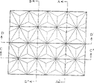
Fig. 1 is the front elevation drawing of first embodiment of the invention.
Fig. 2 is the sectional view along the A-A ' line among Fig. 1.
Fig. 3 is the sectional view along the B-B ' line among Fig. 1.
Fig. 4 is the sectional view along the C-C ' line among Fig. 1.
Fig. 5 is the sectional view along the D-D ' line among Fig. 1.
The sectional view that Fig. 6 is replaced by fluted column face (1) for the protruding cylinder surface (1) in Fig. 2 sectional view of first embodiment of the invention.
The sectional view that Fig. 7 is replaced by fluted column face (1) for the protruding cylinder surface (1) in Fig. 3 sectional view of first embodiment of the invention.
Fig. 8 is the schematic diagram of the face of cylinder (1) in the explanation first embodiment of the invention with the position relation of right-angle prism (2).
Fig. 9 is the light path schematic diagram that is used for illustrating observe the diffusing characteristic diffuser in time from the profile direction of Fig. 2.
Figure 10 is the light path schematic diagram of diffusing characteristic diffuser that is used for illustrating the luminous flux of incident ray among Fig. 9 when the profile direction of Fig. 4 is observed and reflected ray.
Figure 11 is the sectional view of explanation second embodiment of the invention.
Figure 12 is the light path schematic diagram of the reflection characteristic of explanation bead (3).
Sectional view when Figure 13 also includes plane (4) for the plane of incidence among explanation the present invention had both included the face of cylinder (1).
Figure 14 is the schematic diagram of explanation equation n * sini=n ' * sini '.
Figure 15 is the light path schematic diagram of explanation diffuse effect of the present invention.
Figure 16 is the sectional view of third embodiment of the invention along A-A ' line among Fig. 1.
Figure 17 is the sectional view of third embodiment of the invention along B-B ' line among Fig. 1.
Figure 18 be in the third embodiment of the invention the protruding composite surface (1) in the sectional view of Figure 16 by recessed composite surface (1) the sectional view during replacement.
Figure 19 be in the third embodiment of the invention the protruding composite surface (1) in the sectional view of Figure 17 by recessed composite surface (1) the sectional view during replacement.
Figure 20 is the sectional view that is combined by the face of cylinder and plane for composite surface (1) in the third embodiment of the invention.
Figure 21 is the light path schematic diagram that direction is observed the diffusing characteristic diffuser in time of analysing and observe that is used to illustrate from Figure 16.
Figure 22 is the sectional view of explanation third embodiment of the invention.
Figure 23 is the sectional view when combining by composite surface (1) and plane (4) for plane of incidence in the explanation third embodiment of the invention.
Figure 24 is the light path schematic diagram of the diffuse effect of explanation third embodiment of the invention.
Figure 25 is the schematic diagram of the arrangement mode of right-angle prism (2) in the explanation third embodiment of the invention, and one of the emitting edge equilateral triangle jiao is in the horizontal direction in this arrangement mode.
Figure 26 is the sectional view when being stamped a flat film (5) on the composite surface (1) in the third embodiment of the invention.
Embodiment
The slide of the reflector plate of first embodiment of the invention for making by mylar.This slide back side is reflecting surface, and is positive for compensating curved surface.Curved surface is used for producing diffuse reflection when angle of reflection is approximately below 2 °.As shown in Figure 8, curved surface is the face of cylinder, and wherein a point and the b distance of ordering is decided to be 130 μ m, and the distance that b point and c are ordered is 130 μ m, and the distance that b point and d are ordered is 12 μ m, and radius of curvature is 625 μ m.To shown in Figure 5, arrange in vertical direction one by one the face of cylinder (1) as Fig. 1.At the back side of slide is right-angle prism (2), the arrangement that links to each other with.The plane of incidence of each right-angle prism is an equilateral triangle, and the triangle length of side is 150 μ m.To be the face of cylinder (1) only tilt to a direction with respect to the plane of incidence of right-angle prism (2) relative position of the face of cylinder (1) and right-angle prism (2), as shown in Figures 2 and 3.
The reflector plate of said structure will plate layer of aluminum at its back side at last to form reflecting surface.It is cut into desired shape (letter or sign) and paste on the substrate and form information board.
When cutting and stickup reflector plate, to notice that the face of cylinder (1) of adjacency should be to place in vertical direction, because reflector plate has orienting reflex.
Can utilize painted transparent polyester to make reflector plate and obtain the reflector plate of required color.This point also can utilize transparent ink print process (as serigraphy) to accomplish.This moment, the thickness of printed layers should take in when determining the radius of curvature on the face of cylinder (1).
The face of cylinder on the reflector plate (1) can become the form that covers even number (as 4 or 6) individual right-angle prisms (2), as shown in figure 11.So then can form the large cylindrical face, molding is easy to manufacture and accurate.The curvature on the face of cylinder (1) changes according to the number of the right-angle prism of its covering and should determine in view of the above, thereby can produce desirable diffuse reflection.
The radius of curvature on the face of cylinder on the reflector plate (1) can be identical everywhere, also can be different according to the position.The reflecting effect of reflector plate on vertical plane is almost completely consistent simultaneously at radius of curvature each point homogeneous phase.And the intensity of reflected light that has the different time reflector plate to send in the each point radius of curvature changes with reflection direction.
In fact, sometimes right-angle prism (2) does not reach theoretical precision when molding is made.The diffusion that produced of face of cylinder this moment (1) is greater than design load, even diffusion to a certain degree also can take place when promptly the plane of incidence of right-angle prism is plane (4).
Desirable diffusing characteristic diffuser can be avoided and obtain to this situation, and method is to consider when determining the radius of curvature on the face of cylinder (1) that molding is considered error or with the face of cylinder (1) reasonably isoplanar (4) combination, as shown in figure 13.
Even the face of cylinder (1) is concave surface (as in the 3rd embodiment as shown in Figure 18 and Figure 19) rather than convex surface, as long as radius of curvature is identical, effect of the present invention is constant.
The second embodiment of the present invention shown in Figure 11 is a reflector plate (tabular) by synthetic resin (as Merlon and acrylic resin) manufacturing.Reflecting plate is made up of the face of cylinder (1) and right-angle prism (2), as shown in Figure 8.It is 1300 μ m that the face of cylinder (1) is confirmed as the distance that a point and b are ordered above it, and the distance that b point and c are ordered is 1300 μ m, and b point and d point distance are 137 μ m, and radius of curvature is 6253 μ m.It is 1500 μ m that right-angle prism (2) is confirmed as the length that its equilateral triangle is formed into one side of firing angle.
Structure reflector plate as above will be aluminized at its back side at last to form reflecting surface.This reflector plate can be fixed on the guardrail as reflector, or is installed in the dividing strip, or cuts into suitable size by pasting or being screwed in the service depot.
When being fixed in reflector plate in the service depot, notice that the face of cylinder (1) of adjacency should be placed in vertical direction, because reflector plate has orienting reflex.
Can utilize painted transparent acrylic resin or other synthetic resin to make reflector plate and obtain the reflector plate of required color.
In fact, sometimes right-angle prism (2) does not reach theoretical precision when molding is made.The diffusion that produced of face of cylinder this moment (1) is greater than design load, even diffusion to a certain degree also can take place when promptly the plane of incidence of right-angle prism is plane (4).
Desirable diffusing characteristic diffuser can be avoided and obtain to this situation, and method is to consider the molding error or with the face of cylinder (1) reasonably isoplanar (4) combination, as shown in figure 13 when determining the radius of curvature on the face of cylinder (1).
Even the face of cylinder (1) is concave surface (as shown in Fig. 6 and Fig. 7) rather than convex surface, as long as radius of curvature is identical, effect of the present invention is constant.
The third embodiment of the present invention is the reflector plate shown in Fig. 1,4,5 and 16.This reflector plate is a slide, and about 40 μ m are thick, formed through the molding manufacturing by acrylic resin.There is a reflecting surface at its back side.The front of reflector plate is made of the composite surface of adjacency.Each composite surface is the face of cylinder and the curved surface formation of 625 μ m by a radius of curvature.The face of cylinder is oblique to a square neck, and curved surface is to tilting in the other direction.The back side of reflector plate is made up of the right-angle prism (2) of adjacency.Its plane of incidence is the equilateral triangle that the length of side equals 150 μ m.The moulding of the front and back of reflector plate by one-step mould.The area on the face of cylinder accounts for the major part of composite surface (1) area on the front after the moulding, and each composite surface (1) covers two right-angle prisms (2), shown in Fig. 1,4,5,16 and 17.
As above the reflector plate of Gou Chenging will be aluminized at its back side at last to form reflecting surface.It is cut into desired shape (letter or sign) and paste on its plate and form information board.
To note making the face of cylinder downward-sloping (from top view time) when pasting reflector plate in cutting, because reflector plate has orienting reflex.
Can utilize painted transparent polyester to make reflector plate and obtain the reflector plate of required color.This point also can utilize transparent ink print process (as serigraphy) to accomplish.This moment, the thickness of printed layers should take in when determining the radius of curvature on the face of cylinder.
The structure on the face of cylinder on the reflector plate (1) can be that its composite surface covers a plurality of right-angle prisms (2), as shown in figure 22.So then can form the large cylindrical face, molded easy and accurate.If the molding technique no problem, composite surface (1) can be by with the face of cylinder and planar junction altogether and moulding, as shown in figure 20.
Reflector plate of the present invention only makes on this direction that makes progress and penetrates the reverberation diffusion; Yet, making up and can change diffusing characteristic diffuser on request by the face of cylinder that several radius of curvature are different, the brightness that makes reflection is regional area very high (radius of curvature is calculated by aforementioned equation).
In fact, sometimes right-angle prism (2) does not reach theoretical precision when molded.The diffusion that produced of face of cylinder this moment (1) is greater than design load, even diffusion to a certain degree also can take place when promptly the plane of incidence of right-angle prism is plane (4).
Desirable diffusing characteristic diffuser can be avoided and obtain to this situation, and method is to consider molded error or with suitably isoplanar (4) combination of composite surface (1), as shown in figure 13 when determining the radius of curvature on the face of cylinder (1).
Even composite surface (1) is as Figure 18 and Figure 19 shows that concave surface but not convex surface, as long as surface configuration is identical, effect of the present invention is constant.
Reflecting surface with spill composite surface (1) can cover last layer and utilize ultrasonic bonding synthetic resin transparent flat membrane (5), as shown in figure 26.This layer plain film can prevent the empty recess of printing ink filling spill composite surface when utilizing transparent ink that the plane of incidence is printed.
In this embodiment, the arrangement of composite surface (1) will make its slope on above-below direction, and the arrangement of right-angle prism (2) will make an angle of the equilateral triangle on the plane of incidence be in above-below direction.Another kind of arrangement be composite surface (1) arrangement as mentioned above and the arrangement of right-angle prism (2) be to make one jiao of equilateral triangle on the plane of incidence to be on the left and right directions, as shown in figure 16.The result of this latter event is that the angle of reflection of reflected ray is because the optical property of right-angle prism (2) is wideer in a lateral direction.
Reflector plate in the present embodiment with certain diffusion rate with incident ray to source reflection, this diffusion rate can arbitrarily be determined.Because this optical property, this reflector plate can be used indoor wallpaper, and this wallpaper can be from the ceiling reflection ray that makes progress.This makes the whole room reflection ray that makes progress with generation.The effect that this makes whole room seem bright generation.This reflector plate also will obtain other application industrial.
Reflector plate of the present invention also can be made into sheet form (about 1000 μ m are thick), will be described below.Reflector plate can be formed through molded by transparent resin (as Merlon and acrylic resin) or glass.Its back side is reflecting surface.Its front is made up of the composite surface (1) of adjacency.Each composite surface is formed and is comprised that a radius of curvature is the face of cylinder of 6253 μ m (from top view time it is only downward-sloping) and a curved surface (it only is inclined upwardly).The back side of reflector plate is made up of the right-angle prism (2) of adjacency.The plane of incidence of each prism is the equilateral triangle that the length of side equals 1500 μ m.The face of cylinder that consists of wherein of composite surface (1) constitutes the most of of composite surface area and covers two right-angle prisms (2), shown in Fig. 1~5.The front of reflector plate and the back side form by synthetic resin is molded.
The reflecting plate of making as mentioned above wants its back side to aluminize to form reflecting surface at last.This reflecting plate can be used as reflector, can be fixed on the guardrail, or be installed in the dividing strip, or cut into suitable size by gluing very or being screwed in the service depot.
When being fixed in reflecting plate in the service depot, should note making the slope on the face of cylinder towards the below (the time), because reflecting plate has orienting reflex from top view.
Can utilize painted transparent acrylic resin or other synthetic resin to make reflecting plate and obtain the reflecting plate of required color.
In fact, sometimes right-angle prism (2) does not reach theoretical precision when molded.The diffusion on face of cylinder this moment (1) is greater than design load, even diffusion to a certain degree also can take place when promptly the plane of incidence of right-angle prism is plane (4).
Desirable diffusing characteristic diffuser can be avoided and obtain to this situation, and method is to consider molded error or with reasonably isoplanar (4) combination of composite surface (1), as shown in figure 23 when determining the radius of curvature on the face of cylinder for composite surface (1).
Even composite surface (1) is as Figure 18 and Figure 19 shows that concave surface but not convex surface, as long as surface configuration is identical, effect of the present invention is constant.
Other embodiment outside above-mentioned will as in appended claim, proposed, within essence of the present invention and scope, carry out description roughly.
The first embodiment of the present invention produces following effect.
It is as follows that reflector plate is reflected into the ray mode: the angle between incident ray (being sent by automobile or motorcycle headlight) and the reflected ray (towards the driver) always is positioned at the vertical plane vertical with reflector plate.The diffuse reflection of reflector plate or reflector can be satisfactory for practical application, as long as its aspect is perpendicular to reflector plate.
According to this principle, reflector plate of the present invention is characterised in that the reflection of high directivity of the right-angle prism (2) as reflector element is owing to replacing a series of spheres to be compensated with a series of faces of cylinder (1) on plane of incidence.The face of cylinder makes direction and elimination in the other direction the diffuse reflection of a reflected ray directed in orthogonal in reflector plate.The loss of the reflected ray that this diffuse reflection that can reduce can to produce in other cases causes.Therefore, reflector plate of the present invention is more more effective than the common reflector plate that adopts bead, and brightness is higher.
Adopting bead or right-angle prism to be difficult to the brightness of control reflected ray in as the common reflector plate of reflector element, because brightness everywhere changes with angle of reflection is different.Yet, can be controlled owing to adopt the different face of cylinder combination of radius of curvature or the face of cylinder and the formed plane of incidence of planar combination in the present invention.
The reflected ray of this reflector plate is only not only set up during perpendicular to reflector plate at incident ray in this character of propagating on the direction perpendicular to the plane of incidence, and also sets up during the directive reflector plate sideling from the side at incident ray.Under latter event, reflected ray is also only propagated on the direction perpendicular to reflector plate.This reflection characteristic is very desirable to practical application.
Third embodiment of the invention produces following effect.
It is as follows that reflector plate is reflected into the ray mode: the angle between incident ray (being sent by automobile or motorcycle headlight) and the reflected ray (towards the driver) always is positioned at the vertical plane vertical with reflector plate.Driver's viewpoint always is higher than the headlight of automobile or motorcycle.Therefore, as long as irreflexive direction is higher than light source a little, the diffuse reflection of reflector plate can be satisfactory for practical application.
According to this principle, emission sheet of the present invention is characterised in that the reflection of high directivity of the right-angle prism (2) as reflector element is owing to replacing a series of spheres to be compensated with a series of faces of cylinder (1) on plane of incidence.The slope direction on the face of cylinder upwards, therefore the catoptrical direction of propagation in perpendicular to the vertical plane of reflector plate for to make progress a little by light source.The loss of the reflected ray that this diffuse reflection of just having eliminated the diffuse reflection on other directions and having reduced can to produce in other cases causes.Therefore, reflector plate of the present invention is more more effective than the common reflector plate that adopts bead, and brightness is higher.
The invention solves and the related problem of common reflector plate.It also is the brightness of the present invention's reflected ray can be increased in viewing angle greatly and be 2 ° the time.Consequently the visibility of reflective marker has raising for the driver closely the time.Therefore, reflector plate of the present invention can go far towards to prevent because the night traffic accident that road sign visibility deficiency is caused.
Claims (2)
Applications Claiming Priority (6)
| Application Number | Priority Date | Filing Date | Title |
|---|---|---|---|
| JP6270311A JPH08105017A (en) | 1994-10-07 | 1994-10-07 | Reflective sheet and reflective plate |
| JP270311/1994 | 1994-10-07 | ||
| JP270311/94 | 1994-10-07 | ||
| JP38996/95 | 1995-02-04 | ||
| JP38996/1995 | 1995-02-04 | ||
| JP3899695A JPH08211212A (en) | 1995-02-04 | 1995-02-04 | Reflective sheet and reflective plate |
Publications (2)
| Publication Number | Publication Date |
|---|---|
| CN1137814A true CN1137814A (en) | 1996-12-11 |
| CN1146733C CN1146733C (en) | 2004-04-21 |
Family
ID=26378306
Family Applications (1)
| Application Number | Title | Priority Date | Filing Date |
|---|---|---|---|
| CNB951911007A Expired - Fee Related CN1146733C (en) | 1994-10-07 | 1995-10-06 | reflector plate |
Country Status (9)
| Country | Link |
|---|---|
| US (1) | US5936769A (en) |
| EP (1) | EP0742320A4 (en) |
| KR (1) | KR960706593A (en) |
| CN (1) | CN1146733C (en) |
| AU (1) | AU703146B2 (en) |
| CA (1) | CA2178597A1 (en) |
| MY (1) | MY118486A (en) |
| TW (1) | TW337801U (en) |
| WO (1) | WO1996011303A1 (en) |
Cited By (2)
| Publication number | Priority date | Publication date | Assignee | Title |
|---|---|---|---|---|
| CN106772968A (en) * | 2016-12-29 | 2017-05-31 | 镭蒙(苏州)微光学科技有限公司 | A kind of return smooth secondary utilization device of deviation formula laser |
| CN110031858A (en) * | 2019-05-14 | 2019-07-19 | 广州市吉华勘测股份有限公司 | A kind of formwork monitoring device, system and method |
Families Citing this family (5)
| Publication number | Priority date | Publication date | Assignee | Title |
|---|---|---|---|---|
| KR100266482B1 (en) * | 1998-04-03 | 2000-09-15 | 오세룡 | Safety systems of civil structures such as bridge railings and guardrails |
| US6253477B1 (en) * | 1998-09-23 | 2001-07-03 | Hallmark Technologies, Inc. | Retro-reflective sign |
| US20020131130A1 (en) * | 2001-03-09 | 2002-09-19 | Lightpointe Communications, Inc. | Multi-tenant unit optical network |
| US20100118136A1 (en) * | 2007-06-13 | 2010-05-13 | Riet Jan Arie Pieter Van | Surface inspection device and an arrangement for inspecting a surface |
| RU2501094C1 (en) * | 2012-07-09 | 2013-12-10 | Евгений Артурович Бартули | Warning triangle |
Family Cites Families (12)
| Publication number | Priority date | Publication date | Assignee | Title |
|---|---|---|---|---|
| DE511107C (en) * | 1929-07-17 | 1930-10-25 | August Maier | Reflector |
| GB693922A (en) * | 1949-08-08 | 1953-07-08 | Christa Franke | Improvements in and relating to reflector devices |
| US2685231A (en) * | 1949-12-08 | 1954-08-03 | Gen Motors Corp | Combination reflector and taillight lens |
| DE1922780A1 (en) * | 1969-04-03 | 1970-12-03 | Hans Hillesheim | Molded part with reflective prisms and mold for making them |
| US4145112A (en) * | 1977-07-14 | 1979-03-20 | Minnesota Mining And Manufacturing Company | Low-profile raised retroreflective sheeting |
| JPS5657030A (en) * | 1979-10-15 | 1981-05-19 | Sony Corp | Recurrent screen |
| DE3070933D1 (en) * | 1979-11-27 | 1985-09-05 | Swarovski & Co | Retroreflection plate |
| DE2947719C2 (en) * | 1979-11-27 | 1981-08-27 | D. Swarovski & Co., 6112 Wattens, Tirol | Retroreflector plate |
| JPS6217721A (en) * | 1985-07-16 | 1987-01-26 | Ricoh Co Ltd | floodlight device |
| JPH02250083A (en) * | 1989-03-24 | 1990-10-05 | Moritetsukusu:Kk | Marking sheet |
| JPH0368931A (en) * | 1989-08-08 | 1991-03-25 | Seiko Epson Corp | Screen |
| US5237449A (en) * | 1991-01-29 | 1993-08-17 | Nelson Optics Company, Inc. | Biased lenticular sign system |
-
1995
- 1995-10-06 AU AU36195/95A patent/AU703146B2/en not_active Ceased
- 1995-10-06 CA CA002178597A patent/CA2178597A1/en not_active Abandoned
- 1995-10-06 WO PCT/JP1995/002051 patent/WO1996011303A1/en not_active Ceased
- 1995-10-06 US US08/666,281 patent/US5936769A/en not_active Expired - Fee Related
- 1995-10-06 CN CNB951911007A patent/CN1146733C/en not_active Expired - Fee Related
- 1995-10-06 EP EP95933631A patent/EP0742320A4/en not_active Withdrawn
- 1995-10-06 KR KR1019960703015A patent/KR960706593A/en not_active Ceased
- 1995-10-07 MY MYPI95003009A patent/MY118486A/en unknown
- 1995-10-13 TW TW086204690U patent/TW337801U/en unknown
Cited By (2)
| Publication number | Priority date | Publication date | Assignee | Title |
|---|---|---|---|---|
| CN106772968A (en) * | 2016-12-29 | 2017-05-31 | 镭蒙(苏州)微光学科技有限公司 | A kind of return smooth secondary utilization device of deviation formula laser |
| CN110031858A (en) * | 2019-05-14 | 2019-07-19 | 广州市吉华勘测股份有限公司 | A kind of formwork monitoring device, system and method |
Also Published As
| Publication number | Publication date |
|---|---|
| CA2178597A1 (en) | 1996-04-18 |
| MY118486A (en) | 2004-11-30 |
| US5936769A (en) | 1999-08-10 |
| AU703146B2 (en) | 1999-03-18 |
| EP0742320A4 (en) | 1998-11-18 |
| KR960706593A (en) | 1996-12-09 |
| WO1996011303A1 (en) | 1996-04-18 |
| EP0742320A1 (en) | 1996-11-13 |
| CN1146733C (en) | 2004-04-21 |
| TW337801U (en) | 1998-08-01 |
| AU3619595A (en) | 1996-05-02 |
Similar Documents
| Publication | Publication Date | Title |
|---|---|---|
| CN114312308B (en) | Head-up display | |
| CN1126959C (en) | Dual axis retroreflective articles | |
| CN1288457C (en) | Light redirecting films and film systems | |
| CN1900579A (en) | Device for lighting or signalising, in particular for vehicles | |
| CN1345097A (en) | Optical device for optical element and equipment using the same | |
| CN1701276A (en) | Through screen | |
| CN1675495A (en) | Surface light source device | |
| CN1444057A (en) | Composite polymer lens for forming visible light diffusion on surface | |
| CN1401935A (en) | Lamp for vehicle | |
| CN101055322A (en) | Fresnel lens, prism array, rear projection display apparatus, and illuminating apparatus | |
| JP2015525429A (en) | Lighting glass with built-in deflector | |
| CN88100325A (en) | light signaling device | |
| CN1397023A (en) | Triangle conical three-D angle retrodirective reflection element | |
| CN109799615B (en) | A high-brightness vehicle head-up display device | |
| CN1816719A (en) | Light source device and light deflection element | |
| CN1598688A (en) | Image display device, rear projection type screen used in image display device, fresnel lens sheet, and method of making fresnel lens sheet | |
| CN1618039A (en) | Transmissive screen and projection display device | |
| JP2017188298A (en) | Light source device and electronic apparatus using the same | |
| CN1701275A (en) | Fresnel lens sheet, transmission screen and back projection display unit | |
| CN1701274A (en) | Installation structure for fresnel lens sheet and rear-projection display device | |
| US11365864B2 (en) | Rear lamp having moving infinity mirror effect | |
| CN1137814A (en) | Reflective sheet | |
| WO2020233528A1 (en) | Head-up display device and motor vehicle | |
| CN1632667A (en) | Backlight assembly and stereoscopic image imaging device and method using the backlight assembly | |
| JP2017188311A (en) | Light source device and electronic apparatus using the same |
Legal Events
| Date | Code | Title | Description |
|---|---|---|---|
| C06 | Publication | ||
| PB01 | Publication | ||
| C10 | Entry into substantive examination | ||
| SE01 | Entry into force of request for substantive examination | ||
| C14 | Grant of patent or utility model | ||
| GR01 | Patent grant | ||
| C19 | Lapse of patent right due to non-payment of the annual fee | ||
| CF01 | Termination of patent right due to non-payment of annual fee |