Detailed Description
In order to make the objects, technical solutions and advantages of the present application more clear, the present application will be further described with reference to the accompanying drawings.
The terms "first" and "second," and the like in the description, claims, and drawings of the present application are used solely to distinguish between different objects and not to describe a particular order. Furthermore, the terms "comprising" and "having," as well as any variations thereof, are intended to cover non-exclusive inclusions. Such as a process, method, system, article, or apparatus that comprises a list of steps or elements is not limited to only those steps or elements listed, but may alternatively include other steps or elements not listed, or inherent to such process, method, article, or apparatus.
Reference herein to "an embodiment" means that a particular feature, structure, or characteristic described in connection with the embodiment can be included in at least one embodiment of the application. The appearances of the phrase in various places in the specification are not necessarily all referring to the same embodiment, nor are separate or alternative embodiments mutually exclusive of other embodiments. Those skilled in the art will explicitly and implicitly appreciate that the embodiments described herein may be combined with other embodiments.
In this application, "at least one" means one or more, "a plurality" means two or more, "at least two" means two or three and three or more, "and/or" for describing an association relationship of associated objects, which means that there may be three relationships, for example, "a and/or B" may mean: only A, only B and both A and B are present, wherein A and B may be singular or plural. The character "/" generally indicates that the former and latter associated objects are in an "or" relationship. "at least one item(s) below" or similar expressions refer to any combination of these items. For example, at least one (one) of a, b, or c, may represent: a, b, c, "a and b," a and c, "" b and c, "or" a and b and c.
Some of the terminology involved in the present application is detailed below.
1. Flexible Ethernet (Flexible Ethernet, Flexe)
The Optical Internet Forum (OIF) has released flexible ethernet (FlexE), which is a general technology supporting different ethernet Media Access Control (MAC) layer rates. FlexE introduces the concept of flexible ethernet bonding groups (also referred to as flexegroups or simply bonding groups). The bundling group may be formed by bundling one or more physical layer devices (also may be considered as physical link interfaces, which may be denoted as PHYs), and a bandwidth resource corresponding to one bundling group is a sum of bandwidth resources corresponding to PHYs in the bundling group, so that based on the bundling group, FlexE can satisfy a greater transmission rate and transmission bandwidth.
Fig. 1 is a schematic diagram illustrating a flexible ethernet protocol-based communication system, and fig. 1 is an example of a bundle group including 4 PHYs. The FlexE divides the bandwidth resource of each PHY into a plurality of time slots in a Time Division Multiplexing (TDM) manner, thereby realizing hard isolation of transmission pipeline bandwidth. A flexible ethernet protocol Client (FlexE Client) transmits a service stream on behalf of a time slot (one time slot or multiple time slots) specified in a bundle group, where a plurality of flexible ethernet protocol clients can be carried on one bundle group, one flexible ethernet protocol Client corresponds to one service stream (typically, may be referred to as a Media Access Control (MAC) Client), and a flexible ethernet protocol function layer (also may be referred to as a FlexEshim) layer provides data adaptation and conversion from the flexible ethernet protocol Client to the MAC Client.
FlexE may support functions such as bonding, subrate, channelization, etc. by bonding multiple PHYs. For example, the FlexE may bind multiple 100-bit ethernet (GE) PHY ports, and divide each 100GE port into 20 time slots with 5G as a granule in the time domain, where the FlexE may support services with different ethernet MAC rates. For example, 200G of MAC traffic is supported in a 2 × 100GE bonding group, that is, FlexE bonds a plurality of ethernet ports into one bonding group (group) to support MAC traffic at a rate greater than a single ethernet port, that is, FlexE supports the bonding function. And for another example, the MAC service of 50G is supported in a 100GE bonding group, that is, the MAC service with a rate smaller than the bandwidth of the bonding group or smaller than the bandwidth of a single ethernet port is supported by allocating time slots to the service, that is, the FlexE supports the subrate function. Also for example, in a 2 × 100GE bonding group, simultaneous transmission of one 150G and two 25G MAC services is supported, that is, simultaneous transmission of multiple MAC services in the bonding group is supported by allocating time slots for the services, i.e., FlexE supports channelization functions.
It can be seen that FlexE can transmit multiple service flows in parallel through the bundling group, and service data of the same service flow may be carried on one PHY in the bundling group or may be carried on different PHYs in the bundling group. In other words, the service data of the same service flow can be transmitted to the opposite end through one PHY in the bundling group, and also can be transmitted to the opposite end through a plurality of PHYs in the bundling group. The bandwidth resource of a PHY is usually divided into a plurality of slots, and in actual use, the service data is encapsulated in the slots, and then the slots are mapped to PHYs in the bundling group.
It is to be understood that the bundled group shown in this application may also be referred to as a link group, etc., and the service flow shown in this application may also be referred to as a data flow, etc., and the name of the service flow is not limited in this application.
2. Metropolitan area transport network (metro transport network, MTN)
MTN is a new generation transport network technology system defined by the international telecommunications union (international telecommunication union) on the basis of FlexE design logic for 5G and other new service requirements. For example, as shown in fig. 2, the MTN may include an MTN channel layer (MTN path layer) and an MTN segment layer (MTN section layer). The MTN channel layer includes an MTN channel adaptation layer (MTN path adaptation), an MTN channel termination layer (MTN path tail termination), an MTN channel connection layer (MTN path connection), and the like. The MTN segment layer includes an MTN segment layer adaptation layer (MTN section adaptation) and an MTN segment layer termination layer (MTN section trail termination). Optionally, the MTN segment layer may further include an adaptation layer (adaptation).
It is understood that, the MTN channel adaptation layer, the MTN channel termination layer, the MTN channel connection layer, or the MTN segment layer termination layer may also have other names, for example, the MTN channel adaptation layer may also be referred to as an MTN channel adaptation function module, and the like, which is not limited in this application. It is understood that for the description of the bundling group in the MTN, reference may be made to the description of the bundling group in FlexE, which is not described in detail here.
As shown in fig. 3, a service stream acquired by a sending end may enter an MTN domain MTN channel adaptation layer 3051 through an MAC301 and be adapted to a 64B/66B code block stream, after the 64B/66B code block stream enters an MTN channel termination layer 3052, channel layer Operation Administration and Maintenance (OAM) information is inserted into the 64B/66B code block stream, and the OAM information includes a Bit Interleaved Parity (BIP) result.
Then, the sending end may perform 1.5-layer forwarding through an MTN path connection layer (MTN path connection)3053, that is, determine a corresponding relationship of the ingress port at the MTN path connection layer, thereby determining the port. An MTN section adaptation layer (MTN section adaptation)3061 is an adaptation function from a channel layer to a section layer, and each MAC service stream (for example, in the form of a 64B/66B code block) in the MTN section adaptation layer is interleaved to form a 64B/66B code block stream. Then, the 64B/66B code block stream goes through MTN section layer termination (MTN section termination)3062 and is inserted into overhead information such as section OAM. The 64B/66B code block stream then passes through an adaptation layer (adaptation) into the physical layer for transmission, etc. Illustratively, the stream of 64B/66B code blocks may also pass through scrambling codes 307, channel distributions 308, Alignment Marker (AM) insertion functions 309, etc. in fig. 3. On the contrary, after the receiving end receives the 64B/66B code block stream, the flow direction of the 64B/66B code block stream received by the receiving end is opposite to the flow direction of the 64B/66B code block stream transmitted by the transmitting end. For example, a 64B/66B code block stream received by the receiving end may sequentially pass through, for example, an MTN segment layer, an MTN channel layer, and the like.
As shown in fig. 3, the segment layer of the MTN is functionally similar to OIF FlexE shim from the protocol stack perspective, roughly. The current version of the MTN segment layer reuses compatible Flexe, and the segment layer frame format of the current version of the MTN reserves the Flexe frame format.
It is understood that for the specific description of the MAC301, the coordination sublayer (RS) 302, the physical coding sublayer coding/de-coding (PCS encode/decode)303, etc. in fig. 3, reference may be made to the ethernet model of IEEE 802.3.
3. Code block (block)
P1B/P2B code Block: one encoding scheme may also be referred to as a P1B/P2B bit block (bit block), or may also be referred to as a P1B/P2B block, or may also be referred to as a P1B/P2B coding block, or may also be referred to as a P1B/P2B bit stream, or may also be referred to as a P1/P2 (or P1b/P2b) bit block, or the like. Where P1 denotes the number of payload bits in a code block (or bit block); p2 denotes the total number of bits of a code block, P2-P1 denotes the number of bits of a sync header in a code block, P1, P2 are positive integers, and P2 is larger than P1. For example, the above-mentioned P1B/P2B code blocks may be 8B/10B code blocks, 64B/66B code blocks, 128B/130B code blocks, 256B/258B code blocks, etc., and the specific values of the above-mentioned P1 and P2 are not limited in this application.
The method provided by the present application will be exemplified below by 64B/66B code blocks. It is understood that the 64B/66B code blocks shown below may also be replaced by 64B/66B bit blocks, or 64/66 code blocks, or 64/66 bit blocks, or 64B/66B code blocks, or 64B/66B bit blocks, or 64B/66B bit block streams, or 64B/66B code blocks, etc.
As an example, fig. 4a shows a different pattern definition for a 64B/66B code block. As shown in fig. 4a, 2 bits "10" or "01" of the header are synchronization header bits, and the last 64 bits are payload bits, which can be used to carry payload data, etc. Each row in FIG. 4a represents a pattern definition, where D0-D7 represent data bytes, C0-C7 represent control bytes, S0 represents the beginning of a MAC frame, and T0-T7 represent the end of a MAC frame.
4. Code group (block group)
The code group may include a start code block, one or more data code blocks, and an end code block. Illustratively, the beginning portion of the code group is a beginning code block and the ending portion is an ending code block. In other words, the first code block of a code group is a starting code block and the last code block is an ending code block. In this application, the length of a code group may be a preset length, for example, the length of a data code block in a code group may be 128 bytes, 192 bytes, 256 bytes, 384 bytes, or the like. That is, if the sync header in each code block is not considered, the preset length of the code group may be 144 bytes, 208 bytes, 272 bytes, 400 bytes, or the like, and the specific length of the code group is not limited in the present application. Optionally, the length of each code group is the same. For example, a code group may consist of one start code block, P data code blocks, and one end code block, where P may take any of 16, 24, 32, 48, etc.
Illustratively, fig. 4b shows a schematic diagram of a code group, as shown in fig. 4b, the first row (i.e., corresponding to the starting code block in fig. 4 a) is the starting code block in the code group, the 26 th row (i.e., corresponding to the ending code block in fig. 4 a) is the ending code block in the code group, and the 2 nd to 25 th rows are the data code blocks in the code group. Illustratively, the code group includes payload information, which may be traffic data, and overhead information. The load (payload) position shown in fig. 4b may be used to carry payload information. The overhead information may also be referred to as Operation Administration and Maintenance (OAM) information, or may also be referred to as other information, and the name of the overhead information is not limited in the present application. The fixed overhead location and the extended overhead location shown in fig. 4b may be used to carry overhead information. It is understood that the fixed overhead positions and the extended overhead positions shown in fig. 4b are only examples, and in a specific implementation, they may not be distinguished. As an example, after acquiring the code group, the communication apparatus may directly extract the overhead information carried in the fixed overhead position. The overhead information carried in the extended overhead position can be obtained by indicating the communication device through the flag bit or the flag information, etc., that is, after the communication device obtains the code group, the overhead information carried in the extended overhead position can be extracted according to the flag bit or the flag information, etc. Thus, it can be avoided that no overhead information is carried in the extended overhead position, while the communication device still detects the extended overhead position.
It is understood that the overhead information shown in this application may also be referred to as an fgDU overhead, and the payload information may also be referred to as an fgDU payload, etc., and the name of the overhead information is not limited in this application.
In this application, the code block may further include CRC information, and in some cases, the CRC information may also be referred to as overhead information of the code block, but in this application, the CRC information is emphasized, so the CRC information and the overhead information are described separately in this application, but this should not be taken as a limitation of this application. It is understood that the overhead information or CRC information may be carried in the beginning code block, the data code block, or the ending code block, which is not limited in this application. Fig. 4b shows an example in which the CRC information is carried in the end code block.
Similarly, as shown in fig. 4c, the left side of fig. 4c shows a schematic diagram of a code group, and the right side of fig. 4c shows a schematic diagram of an ethernet MAC frame. As can be seen from fig. 4c, the present application shows a similar structure of a code group to an ethernet MAC frame. The code group in the application can make the code group compatible with the rate adaptation mode of the MTN channel by simulating (or disguising) the Ethernet MAC frame, thereby ensuring the compatibility of the transmission of the client signal stream.
The idle (idle) code blocks shown in fig. 4b or fig. 4c can be understood to be increased due to rate adaptation. However, the length of the idle code block may not be considered within the length of the code group, and the receiving end may not count the number of the idle code blocks when acquiring the received number. Alternatively, when rate adaptation is required, the communication apparatus may add or delete an idle code group starting with the start code block and ending with the end code block. Meanwhile, when the receiving end determines the receiving number, the receiving end does not count the number of the idle code groups. Under the condition, the accuracy of the number lost by the code groups obtained by the receiving end can be effectively improved. It is understood that the above description is only an example, in a specific implementation, the length of the idle code block may also be considered within the length of the code block, or the receiving end counts the number of the idle code blocks within the received number, and the application is not limited thereto. It is understood that the description of the idle code block or the idle code group is equally applicable to other control code blocks.
The above descriptions regarding code groups are applicable to the first code group and the boundary code group in the embodiment of the present application. As for the difference between the first code group and the boundary code group, reference is made to the following embodiments, which will not be described in detail herein. For example, the overhead information of the boundary code group may include first overhead information (hereinafter, referred to as first overhead information included in the boundary code group), or the overhead information of the boundary code group may further include fourth overhead information. For example, the overhead information of the first code group includes second overhead information (hereinafter, referred to as the second overhead information included in the first code group), or the overhead information of the first code group may further include fifth overhead information. Illustratively, the third overhead information is included in both the overhead information of the boundary code group and the overhead information of the first code group, but the third overhead information included in the boundary code group adjacent to the first code group is different from the third overhead information included in the first code group.
It is understood that the code groups shown in this application may also be referred to as flexible granular data units (fgdus), code block sets or code block clusters, etc., and the name of the code blocks is not limited in this application.
5. CRC information
The CRC information shown in the present application may be used to check the integrity of the code group. For example, the receiving end may process CRC information in a received code group by modulo-2 division, and if the result obtained by the processing has no remainder, it indicates that the code group is checked correctly or successfully, and if the result obtained by the processing has a remainder, it indicates that the code group is checked incorrectly or failed. The receiving end performs CRC check on the code group, and if the code group is successfully checked, the code group is correctly transmitted or the code group has integrity and the like.
In this application, the bit length of the CRC information may include 4 bits, 8 bits, 16 bits, 32 bits, or the like. In other words, the CRC information shown in the present application may include CRC4, CRC8, CRC16, CRC32, and the like. For example, CRC32 has a strong detection capability, and basically, a communication apparatus can check errors of less than 4 bits by CRC32, while errors of more than 4 bits can also be checked by CRC32 with a probability of 0.9999999997671694.
6. First channel
The first channel may be used to transmit the code groups shown herein, which may be transmitted throughout the MTN network. Illustratively, the first channel may provide flexible granularity of end-to-end TDM channel transport services, such as 2.5M to 5G (including 2.5M and/or 5G), to the customer signal.
In this application, a bundling group may be formed by bundling one or more PHYs, and a bandwidth of the bundling group is a sum of bandwidths of the one or more PHYs. Further, the bundled group may be divided into X second slots, and the bandwidth of the second slots may include 5Gbps or 25Gbps, etc. The second channel may include N second slots of the X second slots, and the second channel may be divided into Y first slots, and a bandwidth of the first slot may include 2.5Mbps, 5Mbps, 7.5Mbps, 10Mbps, 100Mbps, or the like. The first lane may include M first slots of the Y first slots. Wherein N is less than or equal to X, M is less than or equal to Y, and both M, N, X and Y are integers greater than or equal to 1.
In other words, in the present application, the first lane includes M first time slots, the M first time slots are included in the second lane, the second lane includes N second time slots, the N second time slots are included in a bundled group, and the bundled group includes one or more PHY links. The second channel is divided into Y first time slots, the M first time slots are included in the Y first time slots, the bundling group is divided into X second time slots, and the N second time slots are included in the X second time slots. Optionally, the bandwidth of the first timeslot in this application may be 2.5Mbps × K, where K is an integer greater than or equal to 1, and K is less than or equal to 2048.
In other words, the present application shows that the slot granularity of the first channel is smaller, and the transport network technique is more flexible than the slot granularity of the MTN. For example, the first channel may be used for transmitting private line traffic, and the like.
Illustratively, one PHY in a bundle group may include three second lanes, as shown in fig. 5a, or two PHYs in a bundle group may include three second lanes, as shown in fig. 5 b. A second slot included in the second channel is included in the bundle group. One of the second channels may include three first channels, and M first slots included in the first channels are included in the second channels, for example. It is to be understood that fig. 5a and 5b are only examples and should not be construed as limiting the present application.
In this application, the first channel may also be referred to as an fgDU channel (or MTN fg channel), a flexible small particle channel (or small particle channel), a low-order channel, or the like, and the second channel may also be referred to as a large particle channel, a high-order channel, or the like, without limiting the name thereof.
7. Receiving quantity and target quantity
In the application, the receiving number is the number of code groups acquired by the receiving end, and the target number is the number of code groups acquired by the receiving end and sent by the sending end. In other words, the target number may be the number of code groups actually transmitted to the receiving end when the transmitting end transmits the code groups. In the process of code group transmission, code groups may be lost, and the like, and therefore, the number of code groups received by the receiving end (i.e., the receiving number) may be smaller than the number of code groups actually transmitted by the transmitting end (i.e., the target number). Or, in the process of code group transmission, if the code group is not lost, the number of code groups received by the receiving end may be equal to the number of code groups actually sent by the sending end.
It is understood that the target number is the number of code groups actually transmitted by the transmitting end acquired by the receiving end, but for the transmitting end, the number of code groups actually transmitted by the transmitting end may be simply referred to as a transmission number (such as the first number or the second number shown below). In various embodiments illustrated herein, the target number may be equal to the number of transmissions, or the target number may be equal to a sum of a plurality of numbers of transmissions.
When the 64B/66B code block traverses different communication devices, for example, from a transmitting end to a receiving end, the receiving end needs to determine a link error rate (or may also be referred to as a link error rate) according to the calculated BIP result and the BIP result sent by the transmitting end. The line error rate here may be referred to as an error rate of the large grain channel or an error rate of the second channel, or the like. Therefore, when the code group provided in the embodiment of the present application passes through different communication apparatuses, for example, when the code group reaches the receiving end from the transmitting end, the receiving end also needs to determine the condition of code group loss according to the received code group and the code group sent by the transmitting end, and further, determine the line error rate.
In view of this, the present application provides a method and an apparatus for determining code group loss, and the method for determining code group loss provided by the present application can effectively determine the condition of code group loss, and further determine the line error rate.
As an example, fig. 6a is a schematic diagram of a network architecture provided in an embodiment of the present application. As an example of the sender, the Client signal stream (e.g., Client in fig. 6 a) passes through the MTN fg adaptation layer to form a code block stream. When the code block stream passes through the MTN fg termination layer, the code block stream is inserted with OAM information or the like (or may be understood as being inserted with overhead information). Alternatively, the code-group stream may be inserted with CRC information as it passes through the MTN fg termination layer. Then, the sending end determines the corresponding relation of the input ports at the MTN fg connection layer, so as to determine the ports. Wherein, at the MTN fg termination layer, the code block stream forms a complete small particle channel (e.g., the first channel). Further, in the MTN channel adaptation layer, one or more small particle channels multiplex M of the Y first time slots into which a large particle channel (e.g., a second channel) is divided. At the MTN channel termination layer, the overhead information such as OAM and the like can be inserted into one path of large granule channel, and at the MTN section layer adaptation layer, one path or multiple paths of large granule channels multiplex and bind N of X second time slots divided by the group. The sending end inserts an overhead code block at the terminal layer of the MTN segment layer every a certain number of code blocks.
Since the code blocks are encapsulated in the form of code blocks, when the code block stream passes through the MTN channel layer and the MTN segment layer, the MTN channel layer and the MTN segment layer perceive the code block stream, and then the code block stream passes through the physical layer and is transmitted to the link.
As shown in fig. 6b, fig. 6b is a schematic diagram of a communication system according to an embodiment of the present application. For example, fig. 6b shows a network architecture in which a transmitting end, an intermediate node 1, an intermediate node 2, and a receiving end are arranged in sequence from left to right. The method for transmitting the code group stream by the transmitting end can refer to the description of fig. 6 a.
In fig. 6b, since the sending end and the receiving end belong to a Provider Edge (PE), the MTN tunnel connection layer and the MTN fg connection layer are not shown in the sending end and the receiving end. And for network devices (providers, P) within the network, intermediate node 1 shows the MTN tunnel connection layer and intermediate node 2 shows the MTN fg connection layer.
After the intermediate node 1 receives the code block stream through the MTN segment layer or the MTN channel layer, the intermediate node 1 can only perceive the code block stream because the code block stream does not pass through the MTN fg layer. The intermediate node 2 may obtain the code block stream through the MTN fg layer, and the intermediate node 2 may also reselect the large granule channel (e.g., reselect the second channel), and send the code block stream to the receiving end through the new large granule channel. After receiving the code block stream, the receiving end extracts the overhead code block from the MTN segment layer terminating layer, and then the MTN segment layer adaptation function demultiplexes the large granule channel from the N second time slots in the bundling group. And the MTN channel termination layer function demultiplexes the small particle channel from the M first time slots in the large particle channel. Therefore, the receiving end can acquire the overhead information (or OAM information and the like) from the small particle channel at the terminating function of the MTN fg layer, and simultaneously, the MTN fg adaptation function recovers the client signal stream from the small particle channel. It can be understood that, since the flow direction of the client signal stream acquired by the receiving end is opposite to the flow direction of the client signal stream transmitted by the transmitting end, for the specific manner of acquiring the client signal stream by the receiving end, the description of the code block stream transmitted by the transmitting end may also be used, and details are not described here.
Optionally, after acquiring (or sensing) the code block stream through the MTN fg layer, the receiving end may also perform CRC check on the code block stream. When the CRC check passes (or the CRC check succeeds), the receiving end can obtain payload information and/or overhead information in the code block stream. Optionally, the receiving end may also obtain overhead information in the code block stream and the like under the condition that the CRC check fails.
It is understood that the above description of the MTN fg layer is only an example, and in a specific implementation, the MTN fg layer may have other names, or the MTN fg layer may have other structures, and the like, and the embodiment of the present application does not limit this.
It is understood that the transmitting end, the receiving end, the intermediate node, and the like shown in the embodiments of the present application may also be collectively referred to as a communication apparatus. The communication device may be a wired device, a wireless device (including a wireless terminal device or a wireless user device, etc.), a switch, a router, a network card, a Packet Transport Network (PTN), (agile transport network, ATN), a Slice Packet Network (SPN), etc., and the specific form of the communication device is not limited in this application. Optionally, the method for determining code group loss provided by the present application may be applied to a communication system including a transmitting end and a receiving end. Alternatively, the communication system may further include an intermediate node located between the transmitting end and the receiving end, in addition to the transmitting end and the receiving end.
The method for determining code group loss provided in the embodiment of the present application will be described below by taking a transmitting end and a receiving end as examples. In the embodiments shown below, the sending end sending code group is shown as sending code group at MTN fg layer, and the receiving end receiving code group is shown as receiving code group at MTN fg layer. It is understood that reference is made to the above description for the code group, the first channel, the receiving number, the target number, etc., which are referred to below, and detailed description is omitted below.
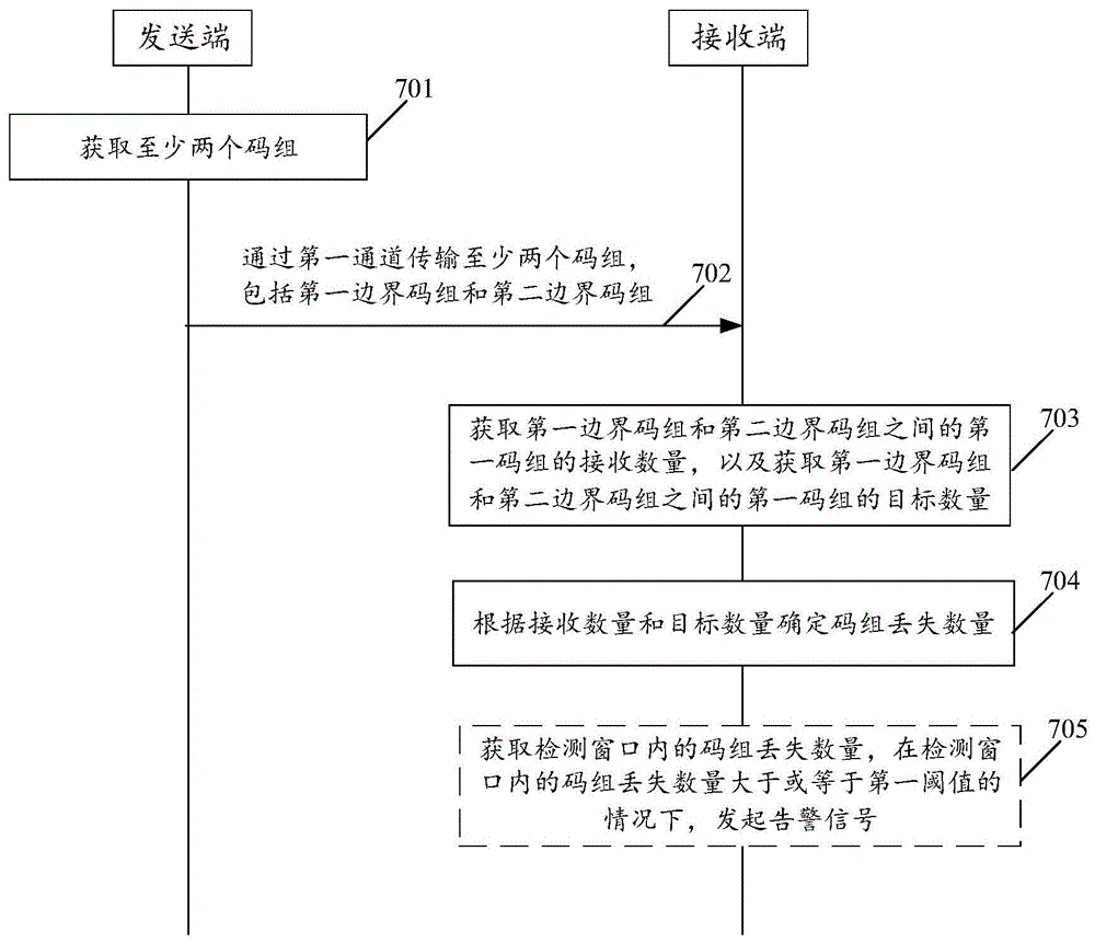
Fig. 7a is a flowchart illustrating a method for determining code group loss according to an embodiment of the present application, where as shown in fig. 7a, the method includes:
701. the sending end obtains at least two code groups, the at least two code groups comprise at least two boundary code groups, and the at least two boundary code groups comprise a first boundary code group and a second boundary code group.
Here, the sending end obtains at least two code groups, which can also be understood as: the transmitting end generates at least two code groups. The format of the transmit end encapsulation code group may be as shown in fig. 4b or fig. 4 c. For how the transmitting end encapsulates the payload information, the overhead information and the CRC information in the code block, reference is made to the above description, and details thereof are not described herein.
Illustratively, the acquiring, by the transmitting end, at least two code groups includes: a sending end sequentially acquires a first boundary code group, a first code group and a second boundary code group; or, the sending end sequentially obtains the first boundary code group, the first code group, the second boundary code group, the first code group and the third boundary code group. Accordingly, the transmitting end may also transmit the above-mentioned at least two code groups according to the illustrated order.
702. The transmitting end transmits at least two code groups to the receiving end through the first channel, and the receiving end receives at least two code groups through the first channel (fig. 7a shows that at least two code groups are transmitted through the first channel), where the at least two code groups include at least two boundary code groups, and the at least two boundary code groups include a first boundary code group and a second boundary code group.
The code group between the first boundary code group and the second boundary code group may be referred to as a first code group, and the first code group is included in the at least two code groups. Optionally, the at least two code groups may further include a third boundary code group, and the like, as to whether the number of the first code groups between the first boundary code group and the second boundary code group is the same as the number of the first code groups between the second boundary code group and the third boundary code group, the embodiment of the present application is not limited. It is understood that the first boundary code group, the second boundary code group, the third boundary code group, and the like shown in the embodiments of the present application may be collectively referred to as a boundary code group.
Optionally, the at least two code groups received by the receiving end may also be code groups for which CRC information check is successful. In other words, when the receiving end receives a code group, the receiving end may perform a CRC check on the code group, and if the CRC check fails, the receiving end may discard the code group. Optionally, if there is an intermediate node between the sending end and the receiving end, the intermediate node may also perform CRC check on the received code group, and if the CRC check fails, the intermediate node discards the code group. In this case, since there is a loss of code groups, the receiving end can determine the number of code group losses according to the following steps 703 and 704. If the intermediate node or the receiving end, etc. successfully performs the CRC check on the code group, the code group may be reserved.
Alternatively, the transmitting end may transmit the boundary code group at a preset period. For example, the transmitting end may transmit the boundary code group at a preset time interval. The preset time interval is used for measuring the time length of sending the code group by the sending end, so the specific value of the preset time interval is not limited in the embodiment of the application. And, the embodiment of the present application does not limit whether the preset time interval can be updated, how to update, and the like. For example, the transmitting end may transmit the boundary code group every one minute. For example, the transmitting end may also transmit the boundary code groups by a preset number of code groups. For example, the transmitting end may transmit the boundary code groups every 100 first code groups. It is understood that the number of preset code groups may be the number of first code groups, or the sum of the number of first code groups and boundary code groups, etc.
Optionally, in the case that the sending end sends the boundary code group in the preset period, the receiving end may also receive the boundary code group in the preset period. It can be understood that for the specific implementation of the transmitting end transmitting the boundary code group and the first code group, reference may also be made to the embodiments shown below.
703. The receiving end acquires the receiving number of the first code group between the first boundary code group and the second boundary code group, and acquires the target number of the first code group between the first boundary code group and the second boundary code group.
In the embodiment of the present application, the above receiving number may be understood as the number of the first code group; alternatively, it can also be understood as the sum of the number of first code groups and first boundary code groups; or, it can also be understood as the sum of the number of first code-groups and second boundary code-groups; or, it can also be understood as the sum of the number of first boundary code groups, first boundary code groups and second boundary code groups. It is understood that the above understanding of the number of receptions is also applicable to the understanding of the number of transmissions of the transmission-end transmission code group (hereinafter, simply referred to as the number of transmissions) in the embodiments shown below. In other words, the understanding of the transmission number and the reception number in the embodiment of the present application is consistent, and if the transmission number is the number of the first code groups transmitted by the transmitting end, the reception number is the number of the first code groups acquired by the receiving end; if the sending number is the sum of the number of the first code groups sent by the sending end and the number of the first boundary code groups (or the second boundary code groups), the receiving number is the sum of the number of the first code groups acquired by the receiving end and the number of the first boundary code groups; if the transmission number is the sum of the number of the first code groups transmitted by the transmitting end and the number of the two boundary code groups (such as the first boundary code group and the second boundary code group), the reception number is the sum of the number of the first code groups acquired by the receiving end and the quality of the two boundary code groups.
For example, during the process of receiving the at least two code blocks, the receiving end obtains the overhead information of the code block, for example, at the MTN fg end layer, so as to distinguish the boundary code block from the first code block according to the difference of the information included in the overhead information. The boundary code groups herein may include two boundary code groups adjacent to the first code group, such as a first boundary code group and a second boundary code group. Specifically, the method for the receiving end to distinguish the boundary code group from the first code group may be as follows:
in one implementation, the first overhead information is included in the boundary code group, and the first overhead information is used to identify the boundary code group. In this case, the receiving end may identify the boundary code group and the first code group according to whether the received at least two code groups include the first overhead information.
Alternatively, the first overhead information may be a flag bit, and for example, the receiving end may distinguish the boundary code group from the first code group by whether the flag bit is included in the code group. For example, if the code group received by the receiving end includes the flag bit, the code group is a boundary code group; if the code group received by the receiving end does not include the flag bit, the code group is the first code group.
Optionally, the boundary code group may further include fourth round-trip information, and the fourth round-trip information may be used to indicate the target number. That is, the receiving end can obtain the target number according to the fourth round-trip information. If the fourth pin information includes the first number, the receiving end may obtain the target number according to the first number; if the fourth pin information includes the first number and the second number, the receiving end may obtain the target number according to the first number; or, the receiving end may obtain the target number according to the second number; alternatively, the receiving end may obtain the target number according to a sum of the first number and the second number. In other words, the first number not only enables the receiving end to obtain the target number, but also enables the receiving end to recognize the boundary code group.
For example, the first overhead information and the fourth overhead information may be located in the same position (or referred to as the same field, different fields, etc.) in the code group. Therefore, the situation that the first overhead information and the fourth overhead information occupy too many bits of the code group can be avoided, and the overhead information in the code group is reduced. For example, the first overhead information and the fourth overhead information may also be located at different positions (or referred to as different fields, different domains, and the like) in the code group, in this case, the receiving end may identify the boundary code group through the flag bit, and then obtain the target number through the first number and/or the second number included in the boundary code group, thereby not only enabling the receiving end to identify the boundary code group, but also enabling the receiving end to obtain the target number more accurately and directly, and improving the accuracy of determining the number lost by the code group.
For example, in the case that the sending end sends the boundary code group in the preset period, the receiving end may further obtain the boundary code group in the preset period. And the receiving end can distinguish the boundary code group from the first code group by whether the transmission number (e.g., the first number and/or the second number) is included in the code group. As shown in the first embodiment below, the receiving end may obtain the boundary code group according to the preset period and the offset window, and the size of the offset window is not limited in this embodiment of the present application. In this case, if the receiving end does not obtain the boundary code group according to the preset period and the offset window, it indicates that the boundary code group may have been lost in the current period. Therefore, the receiving end can obtain the boundary code group according to the preset period and the offset window in the next period.
It is understood that the number of code groups (e.g., the first number) in the current period may be included in the boundary code groups in the current period; or, it may also be included in the boundary code group in the previous cycle; alternatively, the information may be included in the boundary code group in the subsequent period, and the like, which is not limited in the embodiment of the present application.
In another implementation, the first code group includes second overhead information, which identifies the boundary code group. In this case, the receiving end may identify the boundary code group and the first code group according to whether the received at least two code groups include the second overhead information. For the specific description of the second overhead information, the first overhead information may be referred to correspondingly, and is not detailed here. Optionally, the first code group may further include fifth overhead information, where the fifth overhead information is used to indicate the target number. For the specific description of the fifth overhead information, the fourth overhead information may be referred to correspondingly, and will not be described in detail here.
In yet another implementation, the third overhead information is included in each of the at least two code groups, and the third overhead information is used to identify the boundary code group. The third overhead information of two boundary code groups adjacent to the first code group is different from the third overhead information of the first code group. The embodiment of the present application is not limited as to whether the third overhead information of two boundary code groups adjacent to the first code group is the same.
Illustratively, the third overhead information may be a bit sequence. If bit sequences included in two adjacent code groups (e.g., the kth code group and the (k + 1) th code group) received by the receiving end are different, the two adjacent code groups are respectively the first code group and the boundary code group. For example, the kth code group may be a boundary code group (e.g., the first boundary code group), and the (k + 1) th code group may be the first code group. If the bit sequences included in the two adjacent code groups received again by the receiving end are different, the two adjacent code groups are respectively a first code group and a boundary code group. In this case, if the two adjacent code groups received again by the receiving end are the (k + 1) th code group and the (k + 2) th code group, the (k + 2) th code group is the boundary code group (e.g., the second boundary code group). If the two adjacent code groups received again by the receiving end are the k + n1 th code group and the k + n1+1 th code group, the k + n1 th code group is the first code group, and the k + n1+1 th code group is the boundary code group (e.g., the second boundary code group). Therefore, the first code group acquired by the receiving end may be the (k + 1) th code group to the (k + n) 1 th code group. In other words, the receiving end can distinguish the first code group and the boundary code group by the difference of the third overhead information included in the adjacent code groups. The third overhead information may be a bit sequence, for example, the bit sequence may be a 1-bit sequence, a 2-bit sequence, a 3-bit sequence, or the like. As to how many bits the bit length of the bit sequence is, the length of the fixed overhead position and/or the extended overhead position of the code group may be used to determine, or the size of the overhead that can be carried by the code group may also be used to determine, etc.
Illustratively, the third overhead information is serial number information, so that the receiving end can distinguish boundary code groups by the difference of the serial number information of the code groups. As in the third diagram of fig. 7b, the numbers therein can also be understood as serial number information of the code group.
A method for acquiring receiving quantity by a receiving end, for example, when the receiving end receives a boundary code group, a code group loss counter is started; if the receiving end receives the boundary code group again, the code group loss counter is stopped, and the receiving number is obtained according to the code group loss counter. As to how the receiving end identifies the boundary code group, the above detailed description can be referred to. Illustratively, if the receiving end detects that the third overhead information of the code group changes, the code group counter is started; and if the receiving end detects that the third overhead information of the code group changes again, stopping the code group counter. The receiving end can obtain the receiving number according to the code group counter. Illustratively, as shown in fig. 7b, fig. 7b shows three methods for distinguishing the first code group from the boundary code group. In the first diagram of fig. 7b, for block 01, the adjacent block 00 and the adjacent block 10 are boundary blocks of the block 01; for code group 10, the adjacent code group 01 and the adjacent code group 11 are boundary code groups of the code group 10. In the second diagram of fig. 7b, as for code group 0, the adjacent code group 1 is the boundary code group of code group 0; for code group 1, the adjacent code group 0 is the boundary code group of the code group 1. In the third diagram in fig. 7b, for code group 2, code group 1 and code group 3 are boundary code groups of code group 2, and for code group 3, code group 2 and code group 4 are boundary code groups of code group 3. Alternatively, in the third diagram of fig. 7b, code group 0 adjacent to code group 1 and code group 0 adjacent to code group 10 may be boundary code groups of code group 1 to code group 10. It is understood that the numbers shown in fig. 7b are only examples and should not be construed as limiting the embodiments of the present application.
In one implementation, the target number may be included in the set of boundary codes. For example, the transmitting end transmits the boundary code groups in a preset period, and the number of the first code groups in one period may be included in the boundary code groups (e.g., the second boundary code groups) adjacent to the first code groups; or, included in the boundary code groups that are not adjacent to the first code group and are located after the first code group.
In another implementation, the target number may be a preset number. That is, the number of targets acquired by the receiving end may be predetermined, for example, set by a protocol, negotiated set by the transmitting end and the receiving end, and the like.
In yet another implementation, the target number may be determined by a difference between the sequence number information of the first boundary block and the sequence number information of the second boundary block. Alternatively, the target number may be determined according to the sequence number information of the first boundary block and the sequence number information of the second boundary block. For example, the sequence number information of the code group cycles from 0 to SEQmax-1, which can be referred to the description of the third diagram of FIG. 7 b.
It is to be understood that for a specific description of each of the above implementations, reference may also be made to the following.
704. The receiving end determines the number of lost code groups according to the receiving number and the target number.
Namely, the receiving end can obtain the number of lost code groups by comparing the number of the obtained code groups and the number of the code groups sent by the sending end.
In a possible implementation manner, after the receiving end determines the code group loss number according to the receiving number and the target number, the receiving end may further obtain the code group loss number in the detection window. Furthermore, the receiving end can also determine the code group loss rate according to the number of the received code groups in the detection window and the number of the code groups lost in the detection window. I.e. code group loss rate is the number of code group losses in the detection window/the total number of code groups in the detection window. The total number of code groups described herein may include the number of first code groups; alternatively, the number of boundary code groups, etc. may be included. Illustratively, the number of transmissions and the number of receptions correspond to the number of first code groups, and the total number of code groups may be the number of first code groups within the detection window. If the number of transmissions and the number of receptions corresponds to a sum of the number of first code groups and the number of two boundary code groups, the total number of code groups may be the sum of the number of first code groups and the number of boundary code groups within the detection window.
In this application embodiment, can set up the code group in the receiving terminal and lose the counter, from this, the receiving terminal alright lose the counter with utilizing this code group and count the code group quantity that loses. After the receiving end determines that a code group is lost, the receiving end may trigger the code group loss counter to increment by 1, or the value incremented by the code group loss counter may also be determined according to the number of code group losses. In other words, every time the receiving end performs 704, if the number of block losses is, for example, T is greater than or equal to 1, the receiving end triggers the block loss counter to increment by 1, or triggers the block loss counter to increment by T.
In this embodiment of the application, a detection window counter may be further set in the receiving end, and this detection window counter may be used to count the code group received by the receiving end in the detection window. The detection window may include at least two periods, but the detection window is not an integral multiple of a period, and the embodiment of the present application is not limited. Illustratively, in case the receiving end successfully checks the CRC information of one code group, the detection window counter is incremented by 1. And under the condition that the CRC information of one code group is failed to be checked by the receiving end, the detection window counter can not be increased by 1. Because the length of the detection window is far greater than the length of one period, the receiving end can still accurately obtain the code group loss rate under the condition. Or, the receiving end adds 1 to the detection window counter when the CRC information check of one code group fails, and the receiving end can add 1 to the detection window counter when the CRC information check of one code group succeeds. Because the code group acquired by the receiving end is the code group for which the CRC information check is successful, and the lost code group may be the code group for which the CRC information check fails, the receiving end can more accurately acquire the code group loss rate under this condition.
Optionally, in the case that the detection window counter is cleared, the code group loss counter may also be cleared.
In this embodiment of the application, the receiving end can also determine the line error rate according to the number of code blocks lost in the detection window and the total number of code blocks in the detection window.
Because the code blocks shown in the embodiment of the application are of fixed length, a one-to-one correspondence relationship can be established between the code block loss rate and the line error rate, namely the line error rate can be obtained through the code block loss rate. For the relationship between the block loss rate and the line error rate, reference is made to the correlation descriptions of table 1 and table 2. It is understood that the line error rate shown in the embodiment of the present application may also be referred to as an error rate of a small-grain channel or an error rate of a first channel, and the name of the line error rate is not limited in the embodiment of the present application.
705. And initiating an alarm signal under the condition that the number of code group loss in the detection window is greater than or equal to a first threshold value.
Alternatively, the step 705 may be replaced by: and eliminating the alarm signal under the condition that the number of the code group lost in the detection window is less than or equal to a second threshold value.
Illustratively, the value of the block loss counter is greater than or equal to a first threshold (e.g., 20), the receiving end may generate an alarm signal. In this case, the detection window counter continues to count, and the code group loss counter is cleared after the detection window ends (i.e., the detection window counter reaches the window threshold value). Optionally, when the detection window counter reaches the window threshold value, the code group loss counter still does not exceed the first threshold value, and the code group loss counter is still cleared, but does not generate an alarm signal.
Illustratively, in the case of an alarm signal already being present, if the code group loss counter is greater than or equal to the second threshold (e.g., 0, 1, etc.), the alarm cannot be removed, the detection window counter continues to count until the end of the detection window, the code group loss counter continues to count, and the code group loss counter is cleared at the end of the window. Optionally, if the code group loss counter is smaller than the second threshold when the detection window counter reaches the window threshold, the code group loss counter is cleared, and the alarm signal is eliminated.
For example, the alarm signal may include signal degradation (signal degradation) or signal failure (signal failure).
In the embodiment of the application, the code groups are all packaged by adopting the preset length, so that the relation between the line error rate and the code group loss rate is not random any more but determined. Illustratively, the following condition can be satisfied between the block loss rate and the line error rate:
Prbdropblockgroup=1-P(0in)=1-(1-ER)blockgroupLength
wherein, PrbdropblockgroupThe loss rate of the code blocks is represented, P (0in) represents the probability that any bit in the code blocks is correct, BER represents the line error rate, and blockgroupLength represents the length of the code blocks. From the above-shown relationship between the block loss rate and the line error rate, table 1 can be obtained.
In the case of the central limit theorem and the error is too positive distribution, the following formula can be obtained. I.e. the bit error rate of the line detected has a Confidence Level (CL) when how many bits are detected.
Wherein n represents the bit number detected by the receiving end, CL represents the reliability of the line bit error rate, BER represents the line bit error rate, and E represents the second threshold. The above formula shows the number of code groups that the receiving end needs to receive (i.e. the number of code groups included in the detection window) on the basis of a certain reliability and line error rate when eliminating the alarm signal. That is, the relationship between the line error rate and the number of code groups in the detection window shown in table 2 can be obtained by the above formula.
When the second threshold E is equal to 0, i.e. 0 error is detected, the above formula can be simplified as:
therefore, the number of bits to be detected when eliminating the alarm signal, that is, the number of code groups to be detected, can be obtained by the above formula.
Table 1 and table 2 show the relationship between the line error rate and the detection window in the case where the block length is 192 bytes.
TABLE 1
The number of code groups in the detection window required for alarm generation and the corresponding alarm generation thresholds are shown in table 1. For example, when the alarm threshold is set to BER ≧ 10-6The detection window may include 104And (4) each code group. Once more than or equal to 20 code blocks are lost in the detection window, the line error rate is inferior to 10-6And the receiving end generates an alarm signal.
The number of code groups in the detection window and the corresponding alarm cancellation threshold are shown in table 2. For example, if the alarm cancellation threshold is BER ≦ (1 × 10)–6) Then 2x10 may be included in the detection window3And (4) each code group. When detecting the continuously received 2x10³When no code block loss occurs in each code block, the BER of the line is less than or equal to (1 multiplied by 10)–6) And the receiving end eliminates the alarm signal.
TABLE 2
As can be seen from tables 1 and 2, the receiving end can determine whether to generate an alarm signal by detecting the number of code groups in the window and the number of lost code groups; or to eliminate the alarm signal. By establishing the corresponding relation between the line error rate and the code block loss rate, the receiving end can achieve the effect of monitoring the line error rate by monitoring the code block loss rate. It is understood that the code group lengths in tables 1 and 2 refer to the lengths of data code blocks in the code group.
By implementing the embodiment of the application, the receiving end can not only identify the boundary code groups, but also obtain the number of the first code groups between the two boundary code groups, thereby obtaining the receiving number. By comparing the target number and the received number, the number of lost code blocks can be obtained, and the line error condition of the first channel, such as the error rate of the first channel, can be obtained.
To better understand the method shown in fig. 7a, specific embodiments of the method for determining code group loss are provided below.
The first embodiment,
Fig. 8a is a flowchart illustrating a method for determining code group loss according to an embodiment of the present application. This method is exemplified by including the first overhead information and the fourth overhead information in the boundary code group, but it should not be construed as limiting the embodiments of the present application. As shown in fig. 8a, the method comprises:
801. the sending end encapsulates the client signal stream into a code group with a fixed length, the code group takes an S code block as the beginning and a T code block as the end, and the code group comprises payload information, overhead information and CRC information.
802. The transmitting end transmits at least two code groups to the receiving end, and the receiving end receives the at least two code groups. Here, the number of code groups transmitted by the transmitting end and the number of code groups received by the receiving end are not necessarily the same. The transmitting end can also transmit at least two code groups to the receiving end through the first channel, and the receiving end receives the at least two code groups through the first channel.
In order to make the receiving end clearly know the number of code groups sent by the sending end, the sending end can insert the sending number of the code groups sent by the sending end into the overhead information of some code groups. For the sake of distinction, the code group into which the transmission number (i.e., the fourth overhead information) and the flag bit (i.e., the first overhead information) are inserted is referred to as a boundary code group in fig. 8a, and the code group into which the transmission number is not inserted is referred to as a first code group.
In this embodiment of the present application, the sending end may send the boundary code groups at a preset period, for example, send the boundary code groups at a preset time interval or in a preset number of code groups. For example, since the sender sends the boundary code group at a preset period, the sender may insert a flag bit into overhead information of the code group when the MTN fg adaptation layer generates the code group. The number of transmissions is then inserted at the MTN fg termination layer. Or, the sender may insert the flag bits and the sending number in the MTN fg termination layer, and the like, and the embodiment of the present application does not limit when the sender inserts the flag bits and the sending number. For example, the number of code groups to be transmitted in each period by the transmitting end may be predetermined, and the embodiment of the present application is not limited as to whether the number of code groups to be transmitted in each period is the same. In this case, the number of code groups transmitted in each period may be included in any one boundary code group or multiple boundary code groups, which is not limited in this embodiment.
For example, as shown in fig. 8b, when the transmitting end transmits the kth boundary code group, the code group transmission counter is started, and every time the transmitting end transmits one first code group, the code group transmission counter is incremented by 1 until the transmitting end transmits the (k + 1) th boundary code group, and the transmitting end stops the code group transmission counter. In this case, the transmitting end transmits the value of the counter such as P to the code groupk+1(i.e., the fourth overhead information described above) is inserted into the overhead information of the (k + 1) th boundary code group. Or, the Pk+1The method and the device can also be inserted into the overhead information of the k +2 th boundary code group, and the like, which is not limited in this embodiment of the present application. The method for counting the transmitted code group by the code group transmission counter at the transmitting end can lead the P to bek+1The value is more accurate.
Hereinafter, P will be describedk+1The method provided by the embodiment of the present application is exemplified by inserting the overhead information into the (k + 1) th boundary code group.
It is understood that the above code group transmission counter may be reset to 0 every time the transmitting end transmits one boundary code group.
Optionally, the number of transmissions may be the number of first code groups in one period; alternatively, the number of transmissions may be the number of first code groups in each period in adjacent periods. For example, as shown in fig. 8b, the number of transmissions in the overhead information of the k +2 th boundary code group may be Pk+2Or is Pk+2,Pk+1Or is Pk,Pk+1,Pk+2And the like. It can be understood that, in the embodiment of the present application, there is no limitation on how many first code groups in the period are specifically included in the boundary code groups. The following will describe the embodiment of the present application by taking the example that the number of transmissions in the overhead information of one boundary code group is the number of first code groups in each period of two periods.
It is to be understood that the number of the first code groups inserted into the overhead information of the boundary code groups is shown here as an example, but in the embodiment of the present application, the first code groups and the sum of the number of the boundary code groups may also be inserted into the overhead information of the boundary code groups. For example, P may be inserted into the overhead information of the k-th boundary code groupk+1 or Pk+2。
803. The receiving end carries out CRC check on the received code group, and when the CRC check fails, the code group is discarded; when the CRC check passes, the code group is reserved.
It is understood that the receiving end may perform a CRC check on each of the received at least two code groups.
804. The receiving end identifies whether the currently received code group is a boundary code group, such as a first boundary code group, and if the currently received code group is a boundary code group, steps 805 to 808 are executed; if the currently received code group is not the boundary code group, step 809 is executed.
In this embodiment of the present application, if the overhead information of the currently received code group includes a flag bit, the currently received code group is a boundary code group, for example, a first boundary code group. Or, if the overhead information of the currently received code group includes the transmission number, the currently received code group is a boundary code group, such as a first boundary code group.
805. And the receiving end starts the code group counter, receives the boundary code group again, such as the second boundary code group, stops the code group counter, and records the value of the code group counter as Q.
The block counter may be used to count the number of first blocks between two boundary blocks. The method for identifying the boundary code group at the receiving end can refer to the description of step 804, or refer to the description in fig. 7a, etc., and will not be described in detail here.
It is understood that the receiving end may perform the above steps 803 to 805 at the same time; alternatively, the receiving end may also start the code group counter and the like by executing step 803 and step 804, which is not limited in this embodiment.
806. The receiving end transmits the number according to the overhead information of the second boundary code group(such as P)kAnd Pk+1) And acquiring the target quantity.
For example, the target number may be Pk+Pk+1. Wherein, PkCan be understood as the first number, Pk+1This is understood to be the second number.
Illustratively, in step 804, the current code group received by the receiving end is the (k-1) th boundary code group (e.g. the first boundary code group), and then the kth boundary code group is the second boundary code group. Alternatively, if the kth boundary code group has been lost, the (k + 1) th boundary code group is the second boundary code group.
807. Receiving end according to PkAnd Q or Pk+Pk+1The result of the comparison with Q determines the number of block losses.
As shown in FIG. 8c, if (P)k-Q)>0, meaning that the kth boundary code group is not discarded, the number of the first code groups lost between the first boundary code group and the second boundary code group is (P)k-Q), block lost counter + (P)k-Q). If (P)k-Q)<0, indicating that the kth boundary code group is discarded, the number of the first code groups lost between the first boundary code group and the second boundary code group is (P)k+Pk+1-Q), block lost counter + (P)k+Pk+1-Q). It is understood that the code group loss counter + (P) shown in the embodiments of the present applicationk-Q) can also be represented as: code group loss counter plus (P)k-Q), or the value of the block loss counter is increased by (P)k-Q), and the like. Other similar expressions of the embodiments of the present application are also applicable with respect to this description.
Wherein, if (P)k-Q)<0 indicates that at least one boundary code group is lost during the code group transmission. Therefore, the sending end comprises the number of code groups in each period in two adjacent periods, so that the receiving end can resist the condition that one boundary code group is lost.
Optionally, the receiving end may also be according to Pk-1The result of the comparison with Q determines the number of block losses. In other words, in one implementation, the receiving end may interface with any one (or more) of the multiple numbers of transmissions included in the boundary code groupAnd (5) comparing the yield. In another implementation, when the sending end inserts multiple sending numbers into the boundary code group, the sending number in the corresponding period can also be inserted into the corresponding position according to the corresponding relationship between the position and the period. As shown in fig. 4b, the transmitting end may insert the number of code groups (e.g., P) in the current period into OAM _ value1 of the 1 st data code blockk) The number of code groups (e.g., P) in the previous period is inserted into OAM _ value2 of the 2 nd data code blockk-1). Therefore, when the receiving end receives the boundary code group, the receiving end can accurately know the number of the code groups in the current period and the number of the code groups in the previous period.
808. When the number of code group loss in the detection window is larger than or equal to the first threshold value, the receiving end generates an alarm signal. The number of code group losses in the detection window is greater than or equal to the first threshold, that is, the code group loss rate is greater than or equal to the threshold for generating an alarm, and meanwhile, the line error rate is also greater than or equal to the threshold for generating an alarm.
Alternatively, the step 808 may be replaced by: when the number of code group losses in the detection window is less than or equal to a second threshold (e.g., 1 or 0), the alarm signal is removed. The number of code group loss in the detection window is less than or equal to the second threshold, that is, the code group loss rate is less than or equal to the alarm elimination threshold, and meanwhile, the line error rate is less than or equal to the alarm elimination threshold.
It is understood that the detailed description of step 808 can refer to fig. 7a, and will not be described in detail here.
809. Code group counter + 1.
Example II,
Fig. 9a is a flowchart illustrating a method for determining code group loss according to an embodiment of the present application. The method is exemplified by a bit sequence including the third overhead information in the code group, and the third overhead information is 1 bit, but it should not be construed as a limitation to the embodiments of the present application. As shown in fig. 9a, the method comprises:
it is understood that steps 901 to 903 may refer to steps 801 to 803 described above.
In this embodiment of the present application, the sending end may send code groups with a preset number of code groups, in other words, the sending number may be a preset number, that is, the number of code groups in each period may be a fixed value.
In this embodiment of the present application, the sending end may insert a bit sequence (such as the third overhead information mentioned above) into the overhead information of the code group, so that the receiving end may distinguish the boundary code group and the first code group according to the difference of the bit sequence. For example, the overhead information of the code group may include an indication bit 1 (i.e., bit sequence 1) or an indication bit 0 (i.e., bit sequence 0), as the overhead information of the code group in one period may include the same indication bit, i.e., the indication bit may be periodically flipped. As shown in fig. 9b, when the transmitting end transmits the first code group in the period k, the code group transmission counter is started, and when the transmitting end transmits one code group, the code group transmission counter is incremented by 1, and until the transmitting end has transmitted M code groups, the code group transmission counter is stopped. Meanwhile, when the sending end sends the code group, the indication bit 1 is inserted into the overhead information of the code group. Then, the code group transmission counter may be reset to 0, the transmission end counts the code groups in the period k +1, and inserts an indication bit 0 into the overhead information of the code group in the period k + 1.
904. The receiving end recognizes the turning of the indicating bit, and if the indicating bit is turned from 0 to 1, the code group counter is started; and if the indication bit is identified to be turned over again, if the indication bit is turned over from 1 to 0, stopping the code group counter, and recording the value of the code group counter as Q.
905. The receiving end compares M and Q; if M-Q >0, the block loss counter + (M-N) is triggered.
As shown in fig. 9c, when the receiving end recognizes that the indication bit is turned from 1 to 0, the code group counter is started, and when the receiving end recognizes that the indication bit is turned from 0 to 1, the code group counter is stopped, and the value of the code group counter is marked as M2. According to the same method, the receiving end can respectively set the value of the counter, such as M1、M2、M3And M4. Therefore, the receiving end can respectively compare M and M1M and M2M and M3And M4The number of code group losses is obtained.
In this case, the boundary code groups may be as shown in fig. 9c, and for the code groups in the period k +1, the boundary code group 1 and the boundary code group 2 may be understood as the first boundary code group and the second boundary code group, respectively, and the code group in the period k +1 is the first code group. For the code groups in period k +2, the boundary code group 3 and the boundary code group 4 can be understood as a first boundary code group and a second boundary code group, respectively, and the code group in period k +2 is the first code group.
It is appreciated that step 906 can be referenced above with respect to step 808.
In the embodiment of the application, the indication bit is 1 bit, and the receiving end can identify the boundary code group through the 1 bit indication bit, and the overhead of the code group can be reduced.
Example III,
Fig. 10a is a flowchart illustrating a method for determining code group loss according to an embodiment of the present application. This method is exemplified by including the third overhead information in the boundary code group and the third overhead information being serial number information (hereinafter, referred to as code group serial number), but it should not be construed as limiting the embodiments of the present application. As shown in fig. 10a, the method comprises:
it is understood that steps 1001 to 1003 can refer to steps 801 to 803.
In this embodiment, the overhead information of the code group may include a code group sequence number (such as the third overhead information mentioned above), for example, the code group sequence number may cycle from 0 to (SEQmax-1). For example, if the code group serial number of the last code group sent by the sending end is 0, the code group serial number of the current code group is 1, and the code group serial number of the next code group is 2. For another example, if the sequence number of the current code group sent by the sender is (SEQmax-1), the code group sequence number of the next code group is 0. As shown in fig. 10b, the block sequence numbers may cycle from 0 to 15.
1004. And the receiving end compares the acquired code group serial numbers of the two adjacent code groups, and if the code group serial number of the current code group is K, the code group serial number of the last code group is P. If K-P >1, the block loss counter + (K-P) is triggered. If K-P is 1 or (K-P) is (SEQmax-1), then no code block is lost and the counter count of the code block loss is not triggered. If K-P < ═ 0, the block loss counter + (SEGMax- (P-K) -1) is triggered.
Illustratively, the above step 1004 may be replaced by: the receiving end identifies that the serial numbers of two adjacent code groups change, for example, the code group serial number of the previous code group is K1, and the code group serial number of the current code group is K2; if the receiving end recognizes that the serial numbers of two adjacent code groups change again, the code group serial number of the previous code group is K2, and the code group serial number of the current code group is K3. If K3-K1>2, then the block loss counter is triggered + (K3-K1); if K3-K1 is 2 or K3-K1 is (SEQmax-2), it indicates that no code block is lost and does not trigger the code block loss counter to count. If K3-K1< ═ 0, the block loss counter + (SEGMax- (P-K) -2) is triggered. It can be understood that the above-shown method for the receiving end to obtain the code group loss number according to the code group sequence number is only an example.
As shown in fig. 10c, for code group 2, code group 1 and code group 3 can be understood as boundary code groups, such as boundary code group 3 and boundary code group 4, respectively. For code group 1 to code group 15, the two adjacent code groups 0 may be boundary code groups, such as boundary code group 1 and boundary code group 2, respectively. For the receiving end, specifically, the number of code blocks lost is determined by using one code block (or multiple code blocks) as a unit, or the number of code blocks lost is determined by using SEQmax as a unit, and the like, the embodiment of the present application is not limited.
As shown in fig. 10d, if the serial numbers of two adjacent code groups acquired by the receiving end are 0 and 2, the code group loss counter +1 is triggered. If the serial numbers of two adjacent code groups acquired by the receiving end are 15 and 0, no code group is lost. And if the serial numbers of the two adjacent code groups acquired by the receiving end are 8 and 7, triggering a code group loss counter + 13.
It is to be understood that the various numbers shown above are merely examples and should not be construed as limiting the embodiments of the present application.
It is understood that step 1005 may refer to step 808 described above.
In the above three embodiments, exemplarily, as shown in fig. 4b, the flag bit can be carried at the position of SEQ in row 2 (i.e. the first data code block). The indicator bit may be carried at the reserved location of row 2. The code group sequence number may be carried at OAM _ value1 position in line 2 or OAM _ value2 position in line 3 (i.e. the second data code block), etc.
It is understood that the above embodiments are exemplified by two boundary code groups, but the above embodiments can also be applied to a larger number of boundary code groups and first code groups, and will not be described in detail here.
It is to be understood that the above embodiments are shown in the case where the receiving end fails to check the CRC information for the code block and discards the code block. The embodiment of the present application further provides a method, which can successfully check the CRC information on the code group at the receiving end, and shows a case where the code group is not discarded. As shown in fig. 11, the method includes:
1101. the sending end encapsulates the client signal stream into a code group with a fixed length, the code group takes an S code block as the beginning and a T code block as the end, and the code group comprises payload information, overhead information and CRC information.
1102. The transmitting end transmits at least two code groups to the receiving end, and the receiving end receives the at least two code groups.
1103. And the receiving end carries out CRC (cyclic redundancy check) on the received code group, and when the CRC fails, the code group loss counter +1 is triggered.
That is, the receiving end can check the received CRC information of each code group, and if the CRC information check fails, trigger the code group loss counter + 1.
1104. And the receiving end obtains the code group loss number according to the code group loss counter.
In other words, the receiving end can determine the code group loss number according to the code group number of the CRC check failure. For example, the receiving end may determine the number of code group losses in the detection window according to the number of code groups that failed the CRC check, and the like.
1105. When the number of code group loss in the detection window is larger than or equal to the first threshold value, the receiving end generates an alarm signal. The number of code group losses in the detection window is greater than or equal to the first threshold, that is, the code group loss rate is greater than or equal to the threshold for generating an alarm, and meanwhile, the line error rate is also greater than or equal to the threshold for generating an alarm.
It can be understood that the above-illustrated embodiments have respective emphasis, and the implementation manner not described in detail in one embodiment may refer to other embodiments, which are not described in detail here. Furthermore, the various embodiments described herein may be implemented as stand-alone solutions or combined in accordance with inherent logic and are intended to fall within the scope of the present application.
It should be understood that, in the various embodiments of the present application, the sequence numbers of the above-mentioned processes do not mean the execution sequence, and the execution sequence of the processes should be determined by their functions and inherent logic, and should not constitute any limitation to the implementation process of the embodiments of the present application.
The following will describe a communication apparatus provided in an embodiment of the present application.
Fig. 12 is a schematic structural diagram of a communication device according to an embodiment of the present disclosure, where the communication device may be used to perform the method shown in fig. 7a, fig. 8a, fig. 9a, fig. 10a, or fig. 11 in the foregoing embodiments. As shown in fig. 12, the communication apparatus includes a transceiving unit 1201 and a processing unit 1202. Wherein,
a transceiving unit 1201, configured to receive at least two code groups, where the at least two code groups include at least two boundary code groups, and the at least two boundary code groups include a first boundary code group and a second boundary code group;
a processing unit 1202, configured to obtain a receiving number of a first code group between a first boundary code group and a second boundary code group, where the first code group is included in the at least two code groups; and obtaining a target number of the first code group between the first boundary code group and the second boundary code group; and determining the number of lost code groups according to the receiving number and the target number.
In a possible implementation manner, the processing unit 1202 is specifically configured to determine the code group loss number according to the receiving number, and a sum (i.e., a target number) of the first number and the second number when the receiving number is greater than the first number or the receiving number is greater than the second number.
In a possible implementation, the processing unit 1202 is specifically configured to determine the target number by a difference between the third overhead information of the first boundary code group and the third overhead information of the second boundary code group.
In a possible implementation manner, the transceiving unit 1201 is specifically configured to receive at least two code groups through a first channel.
In a possible implementation, the processing unit 1202 is further configured to determine a line error rate according to the number of code group losses in the detection window.
In a possible implementation manner, the processing unit 1202 is further configured to obtain a code group loss number in the detection window; initiating an alarm signal under the condition that the number of code group loss in the detection window is greater than or equal to a first threshold value; or eliminating the alarm signal under the condition that the number of lost code groups in the detection window is less than or equal to a second threshold value.
It is to be understood that, with respect to the descriptions of the first boundary code group, the second boundary code group, the first code group, the number of receptions, the number of targets, the first channel, the second channel, and the first overhead information, the second overhead information, the third overhead information, the fourth overhead information, and the fifth overhead information, etc., reference may be made to the foregoing various embodiments, etc., and no detailed description will be given here.
Exemplarily, the processing unit 1202 may also be configured to perform step 803 to step 808 or step 809 in fig. 8a, etc. Alternatively, the processing unit 1202 may also be configured to perform steps 903 to 906 and the like in fig. 9 a. Alternatively, the processing unit 1202 may also be configured to perform steps 1003 to 1005, etc. in fig. 10 a. Alternatively, the processing unit 1202 may also be configured to execute step 1103 to step 1105 and the like in fig. 11. Illustratively, the processing unit 1202 may be configured to invoke the transceiving unit 1201 to perform the receiving and/or transmitting functions.
For specific implementation of the processing unit 1202 and the transceiving unit 1201, reference may also be made to the above-described embodiments and the like, and details are not described here.
The above embodiments illustrate the communication apparatus as the receiving side in the above embodiments. It is to be understood that the communication apparatus shown in fig. 12 can also be used as the transmitting end in the above embodiments, for example, the processing unit 1202 can also be used to acquire at least two code groups, and the transceiving unit 1201 can also be used to transmit the at least two code groups. For a specific implementation of the communication apparatus as a transmitting end, reference may be made to steps performed by the transmitting end in the methods shown in fig. 7a, fig. 8a, fig. 9a, fig. 10a or fig. 11.
It is to be understood that when the communication apparatus shown in fig. 12 is a communication apparatus or a component of a communication apparatus for implementing the above functions, the processing unit 1202 may be one or more processors, and the transceiving unit 1201 may be a transceiver, or the transceiving unit 1201 may also be a transmitting unit and a receiving unit, where the transmitting unit may be a transmitter, and the receiving unit may be a receiver, and the transmitting unit and the receiving unit are integrated into one device, such as a transceiver.
When the communication apparatus is a circuit system such as a chip system, the processing unit 1202 may be one or more processing circuits or the like, and the transceiving unit 1201 may be an input/output interface, which is also referred to as a communication interface, or an interface circuit, or an interface or the like. Or the transceiving unit 1201 may also be a transmitting unit and a receiving unit, the transmitting unit may be an output interface, the receiving unit may be an input interface, and the transmitting unit and the receiving unit are integrated into one unit, such as an input-output interface.
In some implementations, the communication device shown in fig. 12 may be the communication device or a component of the communication device in each of the above method embodiments, which implements the above functions. In this case, the transceiver 1201 may be implemented by a transceiver, and the processing unit 1202 may be implemented by a processor. As shown in fig. 13, the communication device 130 includes one or more processors 1320 and a transceiver 1310. The processor and transceiver may be used to perform functions or operations, etc., performed by the communication device described above. Alternatively, the processor and the transceiver may be further configured to perform functions or operations performed by the transmitting end or the receiving end.
In this case, reference may be made to fig. 12 for functions or operations, etc. performed by the transceiver 1310 and/or the processor 1320, which will not be described in detail herein.
In various implementations of the communications apparatus shown in fig. 13, the transceiver may include a receiver for performing a receiving function (or operation) and a transmitter for performing a transmitting function (or operation). And transceivers for communicating with other devices/apparatuses over a transmission medium. The processor 1320 may transmit and receive data and/or signaling using the transceiver 1310, and may be configured to implement the corresponding method described in fig. 7a, fig. 8a, fig. 9a, fig. 10a or fig. 11 in the above method embodiments.
Optionally, the communication device 130 may also include one or more memories 1330 for storing program instructions and/or data. A memory 1330 is coupled to the processor 1320. The coupling in the embodiments of the present application is an indirect coupling or a communication connection between devices, units or modules, and may be an electrical, mechanical or other form for information interaction between the devices, units or modules. The processor 1320 may operate in conjunction with the memory 1330. Processor 1320 may execute program instructions stored in memory 1330. Optionally, at least one of the one or more memories may be included in the processor.
The embodiment of the present application does not limit the specific connection medium among the transceiver 1310, the processor 1320, and the memory 1330. In fig. 13, the memory 1330, the processor 1320, and the transceiver 1310 are connected by a bus 1340, which is indicated by a thick line in fig. 13, and the connection manner among other components is only for illustrative purposes and is not limited thereto. The bus may be divided into an address bus, a data bus, a control bus, etc. For ease of illustration, only one thick line is shown in FIG. 13, but this is not intended to represent only one bus or type of bus.
In the embodiments of the present application, the processor may be a general-purpose processor, a digital signal processor, an application specific integrated circuit, a field programmable gate array or other programmable logic device, a discrete gate or transistor logic device, a discrete hardware component, or the like, which may implement or execute the methods, steps, and logic blocks disclosed in the embodiments of the present application. A general purpose processor may be a microprocessor or any conventional processor or the like. The steps of the method disclosed in connection with the embodiments of the present application may be directly implemented by a hardware processor, or implemented by a combination of hardware and software modules in a processor.
It is understood that the communication device shown in the embodiment of the present application may have more components than those shown in fig. 13, and the embodiment of the present application is not limited thereto.
It will be appreciated that the methods performed by the processor and transceiver shown above are merely examples, and reference may be made to the methods described above for the steps specifically performed by the processor and transceiver.
It is understood that, for the communication apparatus shown in fig. 13 being the transmitting end, the specific implementation of the transceiver and the processor may also refer to the foregoing embodiments, and will not be described in detail here. For example, the processor may be configured to generate at least two code groups, and the transceiver may be configured to transmit at least two code groups, and so on.
In other implementations, the communication device shown in fig. 12 may be a circuit system (or a system-on-a-chip, etc.). In this case, the processing unit 1202 may be implemented by a processing circuit, and the transmitting/receiving unit 1201 may be implemented by an interface circuit. As shown in fig. 14, the circuitry may include processing circuitry 1402 and interface circuitry 1401. The processing circuit 1402 may be a chip, a logic circuit, an integrated circuit or a system on chip (SoC) chip, and the like, and the interface circuit 1401 may be a communication interface, an input/output interface, and the like. Illustratively, the processing circuitry and the interface circuitry are coupled to each other. The embodiment of the present application is not limited to a specific connection manner of the processing circuit and the interface circuit.
The interface circuit may be used to obtain data or output data, among other things. For example, the interface circuitry may be configured to obtain at least two code groups, and so on. The processing circuit may be configured to obtain a received number of the first code group between the first boundary code group and the second boundary code group, obtain a target number of the first code group between the first boundary code group and the second boundary code group, and determine a code group loss number according to the received number and the target number.
For another example, the processing circuit may be further configured to determine a line error rate based on the number of code group losses within the detection window. And initiating an alarm signal when the number of code group losses in the detection window is greater than or equal to a first threshold value; or eliminating the alarm signal under the condition that the code group loss number in the detection window is less than or equal to the second threshold value.
It is understood that with regard to the specific implementation of the interface circuit and the processing circuit, reference may be made to the various embodiments illustrated above and will not be described in detail here.
It is to be understood that, for the communication device shown in fig. 14, when it is a transmitting end, the specific implementation of the processing circuit and the interface circuit may also refer to the foregoing embodiments, and will not be described in detail here. For example, the processing circuit may be configured to generate at least two code groups and the interface circuit may be configured to output the at least two code groups.
In the several embodiments provided in the present application, it should be understood that the disclosed system, apparatus and method may be implemented in other ways. For example, the above-described apparatus embodiments are merely illustrative, and for example, the division of the units is only one logical division, and there may be other divisions when actually implementing, for example, a plurality of units or components may be combined or integrated into another system, or some features may be omitted, or not implemented. In addition, the shown or discussed mutual coupling or direct coupling or communication connection may be an indirect coupling or communication connection through some interfaces, devices or units, and may also be an electric, mechanical or other form of connection.
The units described as separate parts may or may not be physically separate, and parts displayed as units may or may not be physical units, may be located in one place, or may be distributed on a plurality of network units. Some or all of the units can be selected according to actual needs to achieve the technical effects of the solutions provided by the embodiments of the present application.
In addition, functional units in the embodiments of the present application may be integrated into one processing unit, or each unit may exist alone physically, or two or more units are integrated into one unit. The integrated unit can be realized in a form of hardware, and can also be realized in a form of a software functional unit.
The integrated unit, if implemented in the form of a software functional unit and sold or used as a stand-alone product, may be stored in a computer readable storage medium. Based on such understanding, the technical solution of the present application may be substantially implemented or contributed to by the prior art, or all or part of the technical solution may be embodied in a software product, which is stored in a readable storage medium and includes instructions for causing a computer device (which may be a personal computer, a server, or a network device) to execute all or part of the steps of the method according to the embodiments of the present application. And the aforementioned readable storage medium includes: various media capable of storing program codes, such as a usb disk, a removable hard disk, a read-only memory (ROM), a Random Access Memory (RAM), a magnetic disk, or an optical disk.
Further, the present application also provides a computer program for implementing the operations and/or processes performed by the communication apparatus in the method for determining code group loss provided by the present application.
The present application also provides a computer-readable storage medium having stored therein computer code, which, when run on a computer, causes the computer to perform the operations and/or processes provided herein for determining code group loss by a communication device.
The present application also provides a computer program product comprising computer code or a computer program which, when run on a computer, causes the operations and/or processes performed by the communication device in the method of determining code group loss provided herein to be performed.
The present application further provides a communication system, where the communication system includes a transmitting end and a receiving end, and specific implementation manners of the transmitting end and the receiving end may refer to the foregoing embodiments, and detailed descriptions thereof are omitted here. For example, the transmitting end may be configured to perform steps 701 and 702 shown in fig. 7a, and the receiving end may be configured to perform steps 703 to 705 shown in fig. 7 a. Optionally, the communication system may further include an intermediate node, and for a specific implementation manner of the intermediate node, reference may be made to steps executed by the receiving end, or reference may also be made to fig. 6b and the like.
The above description is only for the specific embodiments of the present application, but the scope of the present application is not limited thereto, and any person skilled in the art can easily conceive of the changes or substitutions within the technical scope of the present application, and shall be covered by the scope of the present application. Therefore, the protection scope of the present application shall be subject to the protection scope of the claims.