CN1138445C - equipment sound system - Google Patents
equipment sound system Download PDFInfo
- Publication number
- CN1138445C CN1138445C CNB981094619A CN98109461A CN1138445C CN 1138445 C CN1138445 C CN 1138445C CN B981094619 A CNB981094619 A CN B981094619A CN 98109461 A CN98109461 A CN 98109461A CN 1138445 C CN1138445 C CN 1138445C
- Authority
- CN
- China
- Prior art keywords
- woofer
- pair
- panel
- sound
- equipment
- Prior art date
- Legal status (The legal status is an assumption and is not a legal conclusion. Google has not performed a legal analysis and makes no representation as to the accuracy of the status listed.)
- Expired - Fee Related
Links
Images


Classifications
-
- H—ELECTRICITY
- H04—ELECTRIC COMMUNICATION TECHNIQUE
- H04R—LOUDSPEAKERS, MICROPHONES, GRAMOPHONE PICK-UPS OR LIKE ACOUSTIC ELECTROMECHANICAL TRANSDUCERS; ELECTRIC HEARING AIDS; PUBLIC ADDRESS SYSTEMS
- H04R5/00—Stereophonic arrangements
- H04R5/02—Spatial or constructional arrangements of loudspeakers
Landscapes
- Physics & Mathematics (AREA)
- Engineering & Computer Science (AREA)
- Acoustics & Sound (AREA)
- Signal Processing (AREA)
- Details Of Audible-Bandwidth Transducers (AREA)
- Obtaining Desirable Characteristics In Audible-Bandwidth Transducers (AREA)
- Television Receiver Circuits (AREA)
Abstract
本发明提供一种设备的音响装置,它能够改进设备音响装置的音质。在具有低音扬声器(4)和高频扬声器(5)的设备音响装置10中,设备音响装置10包括一个面板(3),它形成设备外壳(2)的一部分,具有许多孔(H),一个声音传播器(8),它位于低音扬声(4)器和面板(3)之间,一个缓冲件(9),它位于声音传播器(8)和面板(3)之间,它能够吸收振动。

The present invention provides an audio device for equipment capable of improving the sound quality of the audio device for equipment. In an equipment audio unit 10 having a woofer (4) and a tweeter (5), the equipment audio unit 10 comprises a panel (3) forming part of the equipment housing (2) having a number of holes (H), a A sound spreader (8), which is located between the woofer (4) and the panel (3), a buffer (9), which is located between the sound spreader (8) and the panel (3), which absorbs vibration.
Description
技术领域technical field
本发明涉及一种用于具有低音扬声器、高频扬声器和显示部分的视频设备的音响装置以及一种相应的视频设备。The invention relates to an audio device for a video device having a woofer, a tweeter and a display part and a corresponding video device.
背景技术Background technique
在最新的视频设备中,如电视机和计算机的显示器,为了扩大显示面,同时尽可能地减小设备本体的体积,或者由于受到其设计条件的限制,阴极射线管(CRT)的周缘的宽度就变得较小以及视频设备箱与阴极射线管之间的空间也变得狭窄。因此,扬声器相应地位于视频设备箱的一面板上以便环绕阴极射线管。在位于阴极射线管和也是视频设备盒的箱体之间的空间的音响装置中,扬声器的体积就做得很小。然而,体积小的扬声器会使扬声器发出的声压通常变得较低,狭窄的面板会使视频设备的音质受到损坏。此外,扬声器位于阴极射线管的附近时,由于扬声器或其发出的声波的颤动,就会干扰阴极射线管的图象。In the latest video equipment, such as televisions and computer monitors, in order to enlarge the display surface while reducing the volume of the equipment body as much as possible, or due to the limitation of its design conditions, the width of the periphery of the cathode ray tube (CRT) becomes smaller and the space between the video equipment box and the cathode ray tube becomes narrow. Accordingly, the speakers are accordingly located on one panel of the video equipment box so as to surround the cathode ray tubes. In the audio system located in the space between the cathode ray tube and the cabinet which is also the video equipment box, the loudspeaker is made very small. However, the sound pressure from the speaker is generally low due to the small size of the speaker, and the sound quality of the video equipment is damaged by the narrow panel. In addition, when the speaker is located near the cathode ray tube, the image of the cathode ray tube may be disturbed due to the vibration of the speaker or the sound waves emitted by the speaker.
此外,如图9A所示,由于常用音响设备的面板PA向外与观众的位置P相对,观众的方向R和声波的前进方向之间的不一致性在观众的位置P会使音质受到损坏,如图9B所示。In addition, as shown in FIG. 9A , since the panel PA of the common audio equipment is outwardly facing the position P of the audience, the inconsistency between the direction R of the audience and the advancing direction of the sound wave at the position P of the audience will damage the sound quality, as Figure 9B.
目前,对于电视设备和类似物的音响装置来说,已经制造出各种器件以改进音质。Currently, for audio devices of television equipment and the like, various devices have been manufactured to improve sound quality.
例如,扬声器的一部分喇叭是由阴极射线管的外侧面和电视机箱体的侧壁形成的。在扬声器的喇叭和阴极射线管的外侧壁中设有用于纠正音质的声音吸收材料。For example, a part of the horn of a loudspeaker is formed by the outer sides of a cathode ray tube and the side walls of a television cabinet. Sound absorbing materials for correcting sound quality are provided in the horn of the speaker and the outer side wall of the cathode ray tube.
有许多用于改进视频设备的扬声器系统的音质的常用技术方案。There are many common technical solutions for improving the sound quality of speaker systems of video equipment.
常用的视频设备的扬声器系统包括一个产生高音的扬声器,一个产生低音的扬声器,低音扬声器固定在具有孔和管的箱体上。这样,其目的是改进低音扬声器发出的音质。A commonly used speaker system for video equipment includes a speaker that produces treble, a speaker that produces bass, and the woofer is fixed to a cabinet with holes and tubes. In this way, the purpose is to improve the sound quality from the woofer.
常用的电视设备是这样设置的,扬声器的固定件安装在视频设备的箱体上,该固定件形成扬声器的管状声道。这样就容许较大的扬声器安装在狭窄的空间。Commonly used television equipment is arranged like this, the fixing part of loudspeaker is installed on the box body of video equipment, and this fixing part forms the tubular sound channel of loudspeaker. This allows larger speakers to be installed in tight spaces.
然而,在常用电视设备的音响装置中,非常害怕扬声器发出的声音影响阴极射线管,因此而使图象受到干扰。此外,很难避免由于受扬声器的声音的影响而使视频设备的箱体产生轻微地振动。However, in audio devices of conventional television equipment, there is a great fear that the sound from the speaker may affect the cathode ray tube, thereby disturbing the picture. In addition, it is difficult to avoid slightly vibrating the cabinet of the video equipment due to the influence of the sound from the speaker.
在电视接收机的声音装置中,扬声器发出的声音可能传递给阴极射线管,以此也使阴极射线管的图象受到干扰。这就很难避免阴极射线管和电视设备的箱体由于受到扬声器和其发出的声音的振动的影响而产生振动。因此,就无法避免图象的质量受到破坏和轻微振动的产生,轻微振动的产生就无法改进高音的声音的品质。In the sound device of the television receiver, the sound from the speaker may be transmitted to the cathode ray tube, thereby disturbing the image of the cathode ray tube as well. It is difficult to avoid the vibration of the casing of the cathode ray tube and the television equipment due to the vibration of the speaker and the sound emitted by it. Therefore, it is unavoidable that the quality of the image is damaged and the generation of slight vibrations cannot improve the quality of the high-pitched sound.
发明内容Contents of the invention
鉴于此方面,本发明的目的是解决上述问题而提供一种设备的音响装置,该设备能够避免音质由于受到低音的扬声器的振动的影响而遭到损坏。In view of this aspect, an object of the present invention is to solve the above-mentioned problems and provide an acoustic device of equipment capable of preventing the sound quality from being damaged due to the vibration of the bass speaker.
根据本发明,上述目的是通过以下的音响装置而实现的。According to the present invention, the above object is achieved by the following acoustic device.
根据本发明的一种用于具有一对低音扬声器、一对高频扬声器和一个显示部分的设备的音响装置,包括:An audio device for a device having a pair of woofers, a pair of tweeters and a display section according to the present invention, comprising:
左和右下部面板部分,它们构成所述设备的外壳的一部分,并且各面板具有多个形成于其上的孔;left and right lower panel portions which form part of the housing of the device, and each panel has a plurality of holes formed therein;
一个声音传播器,它设置在所述一对低音扬声器的各低音扬声器和每一个所述下部面板之间,其中所述一对低音扬声器的前表面设置得平行于所述显示部分的前表面;a sound diffuser disposed between each of said pair of woofers and each of said lower panels, wherein front surfaces of said pair of woofers are disposed parallel to a front surface of said display portion;
一个缓冲件,它设置在各声音传播器和各下部面板部分之间,以吸收来自所述一对低音扬声器的振动;a cushioning member disposed between each sound propagator and each lower panel portion to absorb vibration from the pair of woofers;
左和右上部面板部分,它们构成所述设备的外壳的一部分,并且各面板具有多个形成于其上的孔,其中,left and right upper panel portions, which form part of the housing of the device, and each panel has a plurality of holes formed therein, wherein,
所述一对高频扬声器的各高频扬声器的轴设置得平行于形成在所述上部面板部分上的所述多个孔的每一个孔的轴方向,an axis of each tweeter of the pair of tweeters is disposed parallel to an axis direction of each of the plurality of holes formed in the upper panel portion,
所述一对低音扬声器的各低音扬声器的轴设置得与形成在所述下部面板部分上的所述多个孔的每一个孔的轴方向构成一个倾斜角,使得由所述一对低音扬声器的各低音扬声器发出的声波在传到所述下面板部分时被折射,并且The axes of the respective woofers of the pair of woofers are arranged to form an oblique angle with the axis direction of each of the plurality of holes formed on the lower panel portion so that the woofers of the pair of woofers Sound waves from each woofer are refracted as they travel to the lower panel portion, and
其中,所述左下部面板部分和左上部面板部分相对于所述右下部面板部分和右上部面板部分在相反的方向上倾斜,从而与所述显示部分的前表面构成一个不等于0的锐角θ。Wherein, the left lower panel portion and the left upper panel portion are inclined in opposite directions with respect to the right lower panel portion and the right upper panel portion so as to form an acute angle θ not equal to 0 with the front surface of the display portion .
上述设备是一个视频设备。The above device is a video device.
上述视频设备的显示部分是一个阴极射线管。The display section of the above-mentioned video equipment is a cathode ray tube.
根据本发明的一种具有一对低音扬声器、一对高频扬声器和一个显示部分的视频设备,包括:A video device having a pair of woofers, a pair of tweeters and a display section according to the present invention comprises:
左和右下部面板部分,它们构成所述设备的外壳的一部分,并且各面板具有多个形成于其上的孔;left and right lower panel portions which form part of the housing of the device, and each panel has a plurality of holes formed therein;
一个声音传播器,它设置在所述一对低音扬声器的各低音扬声器和每一个所述下部面板之间,其中所述一对低音扬声器的前表面设置得平行于所述显示部分的前表面;a sound diffuser disposed between each of said pair of woofers and each of said lower panels, wherein front surfaces of said pair of woofers are disposed parallel to a front surface of said display portion;
一个缓冲件,它设置在各声音传播器和各下部面板部分之间,以吸收来自所述一对低音扬声器的振动;a cushioning member disposed between each sound propagator and each lower panel portion to absorb vibration from the pair of woofers;
左和右上部面板部分,它们构成所述设备的外壳的一部分,并且各面板具有多个形成于其上的孔,其中,left and right upper panel portions, which form part of the housing of the device, and each panel has a plurality of holes formed therein, wherein,
所述一对高频扬声器的各高频扬声器的轴设置得平行于形成在所述上部面板部分上的所述多个孔的每一个孔的轴方向,an axis of each tweeter of the pair of tweeters is disposed parallel to an axis direction of each of the plurality of holes formed in the upper panel portion,
所述一对低音扬声器的各低音扬声器的轴设置得与形成在所述下部面板部分上的所述多个孔的每一个孔的轴方向构成一个倾斜角,使得由所述一对低音扬声器的各低音扬声器发出的声波在传到所述下面板部分时被折射,并且The axes of the respective woofers of the pair of woofers are arranged to form an oblique angle with the axis direction of each of the plurality of holes formed on the lower panel portion so that the woofers of the pair of woofers Sound waves from each woofer are refracted as they travel to the lower panel portion, and
所述左下部面板部分和左上部面板部分相对于所述右下部面板部分和右上部面板部分在相反的方向上倾斜,从而与所述显示部分的前表面构成一个不等于0的锐角θ。The left lower panel portion and the left upper panel portion are inclined in opposite directions relative to the right lower panel portion and the right upper panel portion so as to form an acute angle θ not equal to 0 with the front surface of the display portion.
上述显示部分是一个阴极射线管。The above display section is a cathode ray tube.
根据本发明,声音传播器通过缓冲件固定于面板上,该面板形成设备外壳的一部分并具有许多孔。低音扬声器发出的声音经过声音传播器后,再从面板传播给观众的一侧。此时,低音扬声器产生的振动经过缓冲件吸收后以避免面板产生轻微的声音。此外,由于缓冲件的存在还能避免声音从声音传播器中泄漏出去。According to the invention, the sound propagator is fixed by means of a damper to a panel forming part of the housing of the device and having a plurality of holes. The sound from the woofer passes through the sound diffuser and then from the panel to the audience side. At this time, the vibration generated by the woofer is absorbed by the buffer to prevent the panel from producing a slight sound. Furthermore, leakage of sound from the sound transmitter can also be prevented due to the presence of the damper.
根据本发明,通过这样的方式设置高音扬声器,即其轴向最好与面板上的孔向一致或相平行,这样就能使声音传播给观众的一侧时,也不会损坏高音的音质。According to the present invention, the tweeter is arranged in such a way that its axial direction is preferably consistent with or parallel to the hole on the panel, so that when the sound is transmitted to the side of the audience, the sound quality of the tweeter will not be damaged.
附图说明Description of drawings
图1是本发明一个实施例的正视图;Fig. 1 is the front view of an embodiment of the present invention;
图2是沿图1中A-B线的剖视图;Fig. 2 is a sectional view along line A-B in Fig. 1;
图3是本发明一个实施例的低音扬声器的放大视图;Figure 3 is an enlarged view of a woofer according to one embodiment of the present invention;
图4是声音从本发明实施例的低音扬声器中输出声波的示意图;Fig. 4 is the schematic diagram of sound output sound wave from the woofer of the embodiment of the present invention;
图5是沿图1中C-D线的剖视图;Fig. 5 is a sectional view along line C-D in Fig. 1;
图6是本发明实施例的高频扬声器的放大视图;Fig. 6 is the enlarged view of the tweeter of the embodiment of the present invention;
图7是声音从本发明实施例的高频扬声器中输出声波的示意图;Fig. 7 is a schematic diagram of sound outputting sound waves from the tweeter of the embodiment of the present invention;
图8是本发明另一个实施例的剖视图。Fig. 8 is a cross-sectional view of another embodiment of the present invention.
具体实施方式Detailed ways
现在,参考附图在下面详细描述实现本发明的最佳实施例。Now, best embodiments for carrying out the present invention will be described in detail below with reference to the accompanying drawings.
此外,由于下面描述的实施例是本发明的最佳实施例,还可以对其增加各种和更好的技术限制。然而,本发明的范围并不受到这些实施例的限制,除非存在这样的说明即本发明特别受到下面的描述限制。In addition, since the embodiments described below are the preferred embodiments of the present invention, various and better technical limitations can also be added thereto. However, the scope of the present invention is not limited by these examples unless it is stated that the present invention is particularly limited by the following description.
图1是本发明设备的音响装置的一个最佳实施例。参见图1,描述本发明设备的音响装置10。Fig. 1 is a preferred embodiment of the acoustic device of the apparatus of the present invention. Referring to Fig. 1, the
图1是本发明实施例的电视设备(视频设备)的正视图。图2是沿图1A-B线的剖视图。Fig. 1 is a front view of a television device (video device) of an embodiment of the present invention. Fig. 2 is a sectional view along line A-B of Fig. 1 .
图1的视频设备1包括箱体2,具有阴极射线管7的显示部分6,设备的音响装置10,10等。The video equipment 1 of FIG. 1 includes a
视频设备1,例如它是电视设备或计算机的显示部件,包括箱体2。图1中的箱体2包括阴极射线管7,设备的音响装置10,10以及其中的类似部件。图1的箱体2具有左、右面板3、3,如图2所示,面板3、3在相对的方向对应于显示部分6的表面以一个θ角度相互倾斜。A video device 1 , which is for example a television device or a display part of a computer, comprises a
在箱体2的中心设有视频设备1的显示部分6。显示部分6的阴极射线管7能够显示其中的图象。In the center of the
参见图1和图2,详细地描述设备的音响装置10,10。Referring to Figures 1 and 2, the
设备的每个音响装置10,10包括面板3,低音扬声器4,高频扬声器5等。Each
面板3是箱体2的一部分,箱体2是视频设备1的外壳。图1的低音扬声器4通过声音传播器8设置在视频设备1的箱体2的底部。图1的高频扬声器5固定于视频设备1的箱体2的上部。The
参见图3,进一步地详细描述面板3。Referring to Fig. 3, the
图3是低音扬声器4,4安装结构的放大图。左,右面板3,3,例如是由通过微孔处理塑料或金属等组成的,它具有相对孔H。面板3的孔H,例如是由塑料模制或金属穿孔等而形成的。另一种情况是,面板3通过给箱体2提供一塑料件以拉伸的方式而形成的。Fig. 3 is an enlarged view of the installation structure of the
面板3,3设置成通过扩散低音扬声器4和高频扬声器5发出的声音,能减少方向性;并且能减小由于观众位置的差异而导致的声压差。[0015]The
参见图2和图3,描述低音扬声器4和其周缘部。Referring to Fig. 2 and Fig. 3, the
低音扬声器4是一个能够产生频率范围大致为100Hz至400Hz的低音的中、低频扬声器。低音扬声器4,例如是一个直接发射式扬声器,固定在声音传播器8上。The
图2的声音传播器8(也称为波导),例如设置成箱形,位于面板3和低音扬声器4之间。在图3中低音扬声器4固定于声音传播器8的后端孔8a上,声音传播器8的前端孔8b通过缓冲件9连接或固定于面板3上。The sound spreader 8 (also referred to as a waveguide) of FIG. 2 is arranged in a box shape, for example, between the
声音传播器8所起的作用如下。The role played by the
低音扬声器4向其前后发出声波。由于前后声波相位相反,如果它们相互干扰,就会使音质受到损坏。为了使这些前后声波不相互干扰,就必须设置声音传播器8。而且,如图4所示,声音传播器8也起一个从低音扬声器4向面板3传送声波LS,以避免低音扬声器4的振动影响图2的阴极射线管的作用。此外,使用声音传播器8就容许在阴极射线管7的后面所存在的空间中设置较大直径的低音扬声器4。The
参考图3,描述缓冲件9。Referring to FIG. 3 , the cushioning
缓冲件9设置在声音传播器8的前端孔8b上。面板3和声音传播器8通过缓冲件9相互连接而不会有任何空隙。缓冲件9是由诸如橡胶,海绵材料,软塑料或类似的材料制成的。设置缓冲件9的理由如下。The
缓冲件9设置成低音扬声器4的振动传递给声音传播器8时不会传给面板3和阴极射线管7,换句话说,缓冲件9能够避免低音扬声器4传给声音传播器8的振动再传递给面板3而使其产生轻微地振动,它还能避免低音扬声器4产生的声音从声音传播器8中泄漏出去。The
而且,由于缓冲件9位于面板3和声音传播器8之间,这样在组装面板3和声音传播器8时,就能避免气隙的形成,还能避免低音扬声器4发出的声音泄漏出去。因此,缓冲件9起一个避免低音扬声器4的音质受到损坏的作用。Moreover, since the
参考图5和图6,详细地描述高频扬声器5及其周围的部件。Referring to FIGS. 5 and 6 , the tweeter 5 and its surrounding components will be described in detail.
图5是沿图1中的C-D线的剖视图,图6是高频扬声器5和面板3的放大视图。FIG. 5 is a sectional view taken along line C-D in FIG. 1 , and FIG. 6 is an enlarged view of the tweeter 5 and the
高频扬声器5是一个产生声频的范围大致为4000Hz至20000Hz的高音的扬声器。高频扬声器5设置成与视频设备1的箱体2的面板3相连接。高频扬声器5安装成其轴线CL(中心线)与面板3的成型孔H的方向HL相平行。这样安装的原因如下。The tweeter 5 is a speaker that generates high-pitched sound in a range of approximately 4000 Hz to 20000 Hz. The tweeter 5 is arranged to be connected to the
高频声音具有这样的特征即其声压低但是其方向性较强。因此,高频声音具有这样的缺点,即如果面板3和高频扬声器5之间具有较大的空间时,由于声压较低就很难听见声音。而且,它还具有另一个缺点,即如果面板3的成型孔H的方向HL与高频扬声器5的中心线CL(轴线)不相互平行时,由于声音具有较高的方向性,它就不能传播给观众。因此,面板3的成型孔H的方向HL设置成与高频扬声器5的中心线CL相互平行,高频扬声器5要安装成面板3与高频扬声器5之间没有空隙。High-frequency sound has characteristics that its sound pressure is low but its directionality is strong. Therefore, the high-frequency sound has a disadvantage that if there is a large space between the
接着,描述低音扬声器4的声波LS和高频扬声器5的声波HS。Next, the sound wave LS of the
首先,参考图4描述低音扬声器4发出的声波LS。图4中低音扬声器4发出的声音经过声音传播器8碰撞在面板3上。此时,声音传播器8中已碰撞过面板3的声波LS经过面板3折射并通过其中的孔H,因此观众就能听见声音。First, sound waves LS emitted from the
由于面板3,声音传播器8和缓冲件9在低音扬声器4的前部形成一个闭合的空间,这样扬声器箱安装在低音扬声器4后面的情况下,也能重现相同的低音,即使它用于开口空间中,也能使低音扬声器4的膜片产生较小的振幅,还能减弱传递给阴极射线管的振动。Since the
更进一步地说,由于面板3,声音传播器8和缓冲件9形成一闭合的空间,就能抑制扬声器的无效的振动,因此就能削弱其自身的振动。Furthermore, since the
接着,参考图7描述高频扬声器5发出的声波HS。Next, the sound wave HS emitted from the tweeter 5 will be described with reference to FIG. 7 .
图7中高频扬声器5发出的声波HS经过面板3的孔H,按一个方向K传播给观众。In Fig. 7, the sound wave HS emitted by the tweeter 5 passes through the hole H of the
图8是本发明的另一个实施例。Fig. 8 is another embodiment of the present invention.
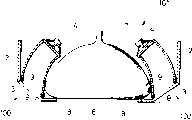
本实施例的设备,例如是一个电视设备。该设备101的音响装置100几乎与图1和图2的设备中的音响装置10一样具有相同的结构。因此,对于图8实施例中设备101的音响装置100的部件与图1实施例中设备1的音响装置10相同的部件,它们用相同的参考标号表示,在此就不作描述了。The device in this embodiment is, for example, a television device. The
在图8中,本实施例与图1和图2中的实施例的差异在于:声音传播器8大致沿阴极射线管7的外周面弯曲。这样,就能使低音扬声器4位于相对具有一个空间的阴极射线管7的后面,在此空间就能容设设备101的音响装置100的较大直径的低音扬声器4。In FIG. 8 , the difference between this embodiment and the embodiments in FIGS. 1 and 2 is that the
如上所述,根据本发明的实施例,它可以提供能够产生高品质声音的设备音响装置。即使在视频设备中,由于避免了面板的振动,阴极射线管的荧光屏也不会产生振动,因此就能避免损坏视频设备的图象质量,使扬声器能够有效地发出声波。这样就能达到节能的预期目的。As described above, according to the embodiments of the present invention, it is possible to provide a device audio device capable of producing high-quality sound. Even in video equipment, since the vibration of the panel is avoided, the fluorescent screen of the cathode ray tube does not vibrate, so that damage to the image quality of the video equipment can be avoided, and the speaker can effectively emit sound waves. In this way, the expected purpose of energy saving can be achieved.
本发明并不局限于这些实施例。The present invention is not limited to these Examples.
例如,一方面,在本发明的实施例中,音响装置10安装在视频设备箱体2的两侧,当然,它也可以毫无问题地仅安装在一侧。而且,音响装置10也可以安装在箱体2的上、下部。For example, on the one hand, in the embodiment of the present invention, the
一方面,在本发明的实施例中,设备的影响装置10包括一个低音扬声器4和一个高频扬声器5,例如,设备的音响装置还可以包括一个低音扬声器4和两个高频扬声器5。On the one hand, in the embodiment of the present invention, the influencing
此外,一方面,在本发明的实施例中,设有低音扬声器4和高频扬声器5,低音扬声器4可以分为一个低音量的扬声器和一个中音量的扬声器以便形成一个三用系统。In addition, on the one hand, in the embodiment of the present invention, a
参考附图已经描述完本发明的最佳实施例,应该明白本发明并不受到上述实施例的限制,本领域的熟练人员可对其作各种修改和润饰而没有脱离后面权利要求所限定的本发明的精神和范围。Having described the best embodiment of the present invention with reference to accompanying drawing, should understand that the present invention is not limited by above-mentioned embodiment, and those skilled in the art can make various modifications and retouches to it and do not depart from the definition of following claims spirit and scope of the invention.
Claims (5)
- One kind be used to have a pair of woofer, the acoustics of the equipment of a pair of tweeter and a display part, comprising:A left side and right lower quadrant faceplate part, they constitute the part of the shell of described equipment, and each panel has a plurality of holes formed thereon;A sound transmission device, it is arranged between each woofer and each described lower panel of described a pair of woofer, and the front surface of wherein said a pair of woofer is provided with to such an extent that be parallel to the front surface of described display part;A bolster, it is arranged between each sound transmission device and each lower panel part, to absorb the vibration from described a pair of woofer;A left side and upper right quarter faceplate part, they constitute the part of the shell of described equipment, and each panel has a plurality of holes formed thereon, wherein,The axle of each tweeter of described a pair of tweeter is provided with to such an extent that be parallel to the direction of principal axis in each hole that is formed on the described a plurality of holes on the described upper panel part,The axle of each woofer of described a pair of woofer is provided with to such an extent that constitute an inclination angle with the direction of principal axis in each hole that is formed on the described a plurality of holes on the described lower panel part, make sound wave that each woofer by described a pair of woofer sends when passing to described lower panel part, be refracted, andWherein, described lower left quarter faceplate part and upper left quarter faceplate part tilt in the opposite direction with respect to described right lower quadrant faceplate part and upper right quarter faceplate part, are not equal to 0 acute angle theta thereby constitute one with the front surface of described display part.
- 2. the acoustics that is used for equipment as claimed in claim 1 is characterized in that: described equipment is a video equipment.
- 3. the acoustics that is used for equipment as claimed in claim 2 is characterized in that: the display part of described video equipment is a cathode ray tube.
- 4. video equipment with a pair of woofer, a pair of tweeter and a display part comprises:A left side and right lower quadrant faceplate part, they constitute the part of the shell of described equipment, and each panel has a plurality of holes formed thereon;A sound transmission device, it is arranged between each woofer and each described lower panel of described a pair of woofer, and the front surface of wherein said a pair of woofer is provided with to such an extent that be parallel to the front surface of described display part;A bolster, it is arranged between each sound transmission device and each lower panel part, to absorb the vibration from described a pair of woofer;A left side and upper right quarter faceplate part, they constitute the part of the shell of described equipment, and each panel has a plurality of holes formed thereon, wherein,The axle of each tweeter of described a pair of tweeter is provided with to such an extent that be parallel to the direction of principal axis in each hole that is formed on the described a plurality of holes on the described upper panel part,The axle of each woofer of described a pair of woofer is provided with to such an extent that constitute an inclination angle with the direction of principal axis in each hole that is formed on the described a plurality of holes on the described lower panel part, make sound wave that each woofer by described a pair of woofer sends when passing to described lower panel part, be refracted, andDescribed lower left quarter faceplate part and upper left quarter faceplate part tilt in the opposite direction with respect to described right lower quadrant faceplate part and upper right quarter faceplate part, are not equal to 0 acute angle theta thereby constitute one with the front surface of described display part.
- 5. video equipment as claimed in claim 4 is characterized in that: described display part is a cathode ray tube.
Applications Claiming Priority (3)
| Application Number | Priority Date | Filing Date | Title |
|---|---|---|---|
| JP66830/97 | 1997-03-19 | ||
| JP9066830A JPH10262293A (en) | 1997-03-19 | 1997-03-19 | Equipment acoustic equipment |
| JP66830/1997 | 1997-03-19 |
Publications (2)
| Publication Number | Publication Date |
|---|---|
| CN1198649A CN1198649A (en) | 1998-11-11 |
| CN1138445C true CN1138445C (en) | 2004-02-11 |
Family
ID=13327155
Family Applications (1)
| Application Number | Title | Priority Date | Filing Date |
|---|---|---|---|
| CNB981094619A Expired - Fee Related CN1138445C (en) | 1997-03-19 | 1998-03-19 | equipment sound system |
Country Status (7)
| Country | Link |
|---|---|
| US (1) | US6335974B1 (en) |
| JP (1) | JPH10262293A (en) |
| KR (1) | KR100532699B1 (en) |
| CN (1) | CN1138445C (en) |
| ID (1) | ID20086A (en) |
| MY (1) | MY120029A (en) |
| SG (1) | SG60214A1 (en) |
Families Citing this family (19)
| Publication number | Priority date | Publication date | Assignee | Title |
|---|---|---|---|---|
| EP1148758A1 (en) * | 2000-04-18 | 2001-10-24 | THOMSON multimedia S.A. | Cabinet for audio devices |
| US6415036B1 (en) * | 2000-08-24 | 2002-07-02 | Thomson Licensing, S.A. | Apparatus for reducing vibrations generated by a loudspeaker in a television cabinet |
| EP1471766B1 (en) * | 2003-04-22 | 2010-11-24 | Thomson Licensing | Electronic device with loudspeaker |
| US20050105748A1 (en) * | 2003-11-14 | 2005-05-19 | Motorola, Inc. | Integrated flexible display and speaker apparatus and method |
| US20060126885A1 (en) * | 2004-12-15 | 2006-06-15 | Christopher Combest | Sound transducer for solid surfaces |
| US7386137B2 (en) * | 2004-12-15 | 2008-06-10 | Multi Service Corporation | Sound transducer for solid surfaces |
| JP5010810B2 (en) * | 2005-05-13 | 2012-08-29 | 三洋電機株式会社 | Electronics |
| JP4528672B2 (en) * | 2005-06-09 | 2010-08-18 | 株式会社東芝 | Video display device |
| CN100499971C (en) * | 2005-11-04 | 2009-06-10 | 群康科技(深圳)有限公司 | Panel display |
| KR100813302B1 (en) | 2006-08-08 | 2008-03-13 | 엘지전자 주식회사 | Computer speakers |
| JP2008072239A (en) * | 2006-09-12 | 2008-03-27 | Sony Corp | Portable electronic devices |
| US8002078B2 (en) * | 2009-02-19 | 2011-08-23 | Bose Corporation | Acoustic waveguide vibration damping |
| JP2011077637A (en) * | 2009-09-29 | 2011-04-14 | Sanyo Electric Co Ltd | Image display device |
| TWI433548B (en) * | 2011-12-16 | 2014-04-01 | Wistron Corp | Speaker device and electronic device having the same |
| IN2014MN02494A (en) | 2012-06-29 | 2015-07-17 | Sony Corp | |
| AU2017203515A1 (en) | 2016-03-08 | 2017-09-28 | Chill Gaming Pty Ltd | Gaming method, system and machine comprising multiple games |
| US10536772B2 (en) * | 2017-04-19 | 2020-01-14 | Chill Gaming Pty Ltd | Audio system |
| JP7556360B2 (en) * | 2019-12-04 | 2024-09-26 | 株式会社ソシオネクスト | Display and audio equipment |
| US20240015426A1 (en) * | 2020-12-21 | 2024-01-11 | Sony Group Corporation | Display Device |
Family Cites Families (16)
| Publication number | Priority date | Publication date | Assignee | Title |
|---|---|---|---|---|
| DE3405128A1 (en) * | 1984-02-14 | 1985-08-22 | Standard Elektrik Lorenz Ag, 7000 Stuttgart | DEVICE FOR STEREOPHONIC SOUND PLAYBACK IN A TELEVISION RECEIVER |
| US5166802A (en) * | 1987-11-25 | 1992-11-24 | Electronic-Werke Deutschland Gmbh | Television receiver with loudspeaker enclosure |
| FR2631195B1 (en) * | 1988-05-06 | 1990-07-27 | Loire Electronique | SOUND SYSTEM, ESPECIALLY STEREOPHONIC FOR TELEVISIONS WITH INTEGRATED LARGE FREQUENCY LARGE SPEAKERS |
| US5181247A (en) * | 1990-07-23 | 1993-01-19 | Bose Corporation | Sound image enhancing |
| JP3104073B2 (en) * | 1990-12-22 | 2000-10-30 | ソニー株式会社 | Speaker device of television receiver |
| JPH0575955A (en) * | 1991-09-10 | 1993-03-26 | Sony Corp | Tv set |
| DE69329918T2 (en) * | 1992-11-18 | 2001-05-31 | Matsushita Electric Industrial Co., Ltd. | Television receiver |
| JPH0759184A (en) * | 1993-03-05 | 1995-03-03 | Matsushita Electric Ind Co Ltd | Housing, audio / visual equipment and manufacturing method thereof |
| US5400408A (en) * | 1993-06-23 | 1995-03-21 | Apple Computer, Inc. | High performance stereo sound enclosure for computer visual display monitor and method for construction |
| JPH0767060A (en) | 1993-08-30 | 1995-03-10 | Hitachi Ltd | Television receiver |
| JPH07222273A (en) | 1994-01-27 | 1995-08-18 | Matsushita Electric Ind Co Ltd | Speaker device and manufacturing method thereof |
| JPH08126087A (en) | 1994-10-20 | 1996-05-17 | Matsushita Electric Ind Co Ltd | Horn speaker holding device |
| KR100195535B1 (en) * | 1995-11-06 | 1999-06-15 | 구자홍 | Screen shake prevention device of video display device |
| US5822443A (en) * | 1996-04-22 | 1998-10-13 | Samsung Electronics Co., Ltd. | Speaker system for a television |
| JPH10313495A (en) * | 1997-05-12 | 1998-11-24 | Sony Corp | Sound equipment |
| KR100250369B1 (en) * | 1997-09-26 | 2000-04-01 | 전주범 | A vibration prevention device of for woofer for television |
-
1997
- 1997-03-19 JP JP9066830A patent/JPH10262293A/en active Pending
-
1998
- 1998-03-06 US US09/035,849 patent/US6335974B1/en not_active Expired - Fee Related
- 1998-03-11 SG SG1998000554A patent/SG60214A1/en unknown
- 1998-03-11 KR KR1019980008036A patent/KR100532699B1/en not_active Expired - Fee Related
- 1998-03-16 ID IDP980374A patent/ID20086A/en unknown
- 1998-03-18 MY MYPI98001190A patent/MY120029A/en unknown
- 1998-03-19 CN CNB981094619A patent/CN1138445C/en not_active Expired - Fee Related
Also Published As
| Publication number | Publication date |
|---|---|
| KR100532699B1 (en) | 2006-02-20 |
| US6335974B1 (en) | 2002-01-01 |
| ID20086A (en) | 1998-09-24 |
| JPH10262293A (en) | 1998-09-29 |
| KR19980080112A (en) | 1998-11-25 |
| CN1198649A (en) | 1998-11-11 |
| MY120029A (en) | 2005-08-30 |
| SG60214A1 (en) | 1999-02-22 |
Similar Documents
| Publication | Publication Date | Title |
|---|---|---|
| CN1138445C (en) | equipment sound system | |
| CN1164143C (en) | Loudspeaker device | |
| CN1075316C (en) | Speakers system of television | |
| JP6932166B2 (en) | Display device | |
| CN1049787C (en) | Loudspeaker system and TV loudspeaker system | |
| CN100342751C (en) | Multiple shock reducing device for loundspeaker device of video displayer | |
| CN103299654B (en) | Display device | |
| CN1647573A (en) | Image display device | |
| KR102682093B1 (en) | Display apparatus | |
| CN208110252U (en) | A kind of Self-sounding projection optics screen | |
| JP2008211381A (en) | Display device | |
| CN112102717A (en) | Display device and sound-emitting screen | |
| CN1083663C (en) | Audio induced interference suppression apparatus for video display appliances | |
| CN112104958A (en) | Display device and electromagnetic actuator | |
| CN113796095A (en) | Loudspeaker equipment, loudspeakers and structures | |
| JP2009038446A (en) | Speaker box structure and thin display device equipped with the speaker box | |
| CN1653848A (en) | Bass reflex type speaker device, mounting structure and mounting method for speaker device | |
| CN1207008A (en) | Sound field equalization device for loudspeaker system | |
| CN212541770U (en) | Sound-transmitting movie screen | |
| CN1303576A (en) | Speaker apparatus and television set | |
| CN1893596A (en) | Image display apparatus | |
| CN112788492B (en) | Display device and speaker assembly | |
| CN1878425A (en) | Speaker device and acoustic output method thereof as well as image display apparatus | |
| CN1110191C (en) | Device for preventing image-jitter resulted from output of acoustic amplifier of image displayer | |
| JP4923657B2 (en) | Speaker device and television receiver using the speaker device |
Legal Events
| Date | Code | Title | Description |
|---|---|---|---|
| C06 | Publication | ||
| PB01 | Publication | ||
| C10 | Entry into substantive examination | ||
| SE01 | Entry into force of request for substantive examination | ||
| C14 | Grant of patent or utility model | ||
| GR01 | Patent grant | ||
| C19 | Lapse of patent right due to non-payment of the annual fee | ||
| CF01 | Termination of patent right due to non-payment of annual fee |