CN113891925A - Process and method for regenerating flammable and non-flammable hydrofluoroolefin-containing refrigerants - Google Patents
Process and method for regenerating flammable and non-flammable hydrofluoroolefin-containing refrigerants Download PDFInfo
- Publication number
- CN113891925A CN113891925A CN202080019707.0A CN202080019707A CN113891925A CN 113891925 A CN113891925 A CN 113891925A CN 202080019707 A CN202080019707 A CN 202080019707A CN 113891925 A CN113891925 A CN 113891925A
- Authority
- CN
- China
- Prior art keywords
- refrigerant composition
- composition
- refrigerant
- regenerated
- module
- Prior art date
- Legal status (The legal status is an assumption and is not a legal conclusion. Google has not performed a legal analysis and makes no representation as to the accuracy of the status listed.)
- Pending
Links
Images





Classifications
-
- F—MECHANICAL ENGINEERING; LIGHTING; HEATING; WEAPONS; BLASTING
- F25—REFRIGERATION OR COOLING; COMBINED HEATING AND REFRIGERATION SYSTEMS; HEAT PUMP SYSTEMS; MANUFACTURE OR STORAGE OF ICE; LIQUEFACTION SOLIDIFICATION OF GASES
- F25B—REFRIGERATION MACHINES, PLANTS OR SYSTEMS; COMBINED HEATING AND REFRIGERATION SYSTEMS; HEAT PUMP SYSTEMS
- F25B9/00—Compression machines, plants or systems, in which the refrigerant is air or other gas of low boiling point
- F25B9/002—Compression machines, plants or systems, in which the refrigerant is air or other gas of low boiling point characterised by the refrigerant
- F25B9/006—Compression machines, plants or systems, in which the refrigerant is air or other gas of low boiling point characterised by the refrigerant the refrigerant containing more than one component
-
- C—CHEMISTRY; METALLURGY
- C09—DYES; PAINTS; POLISHES; NATURAL RESINS; ADHESIVES; COMPOSITIONS NOT OTHERWISE PROVIDED FOR; APPLICATIONS OF MATERIALS NOT OTHERWISE PROVIDED FOR
- C09K—MATERIALS FOR MISCELLANEOUS APPLICATIONS, NOT PROVIDED FOR ELSEWHERE
- C09K5/00—Heat-transfer, heat-exchange or heat-storage materials, e.g. refrigerants; Materials for the production of heat or cold by chemical reactions other than by combustion
- C09K5/02—Materials undergoing a change of physical state when used
- C09K5/04—Materials undergoing a change of physical state when used the change of state being from liquid to vapour or vice versa
- C09K5/041—Materials undergoing a change of physical state when used the change of state being from liquid to vapour or vice versa for compression-type refrigeration systems
- C09K5/044—Materials undergoing a change of physical state when used the change of state being from liquid to vapour or vice versa for compression-type refrigeration systems comprising halogenated compounds
-
- C—CHEMISTRY; METALLURGY
- C09—DYES; PAINTS; POLISHES; NATURAL RESINS; ADHESIVES; COMPOSITIONS NOT OTHERWISE PROVIDED FOR; APPLICATIONS OF MATERIALS NOT OTHERWISE PROVIDED FOR
- C09K—MATERIALS FOR MISCELLANEOUS APPLICATIONS, NOT PROVIDED FOR ELSEWHERE
- C09K5/00—Heat-transfer, heat-exchange or heat-storage materials, e.g. refrigerants; Materials for the production of heat or cold by chemical reactions other than by combustion
- C09K5/02—Materials undergoing a change of physical state when used
- C09K5/04—Materials undergoing a change of physical state when used the change of state being from liquid to vapour or vice versa
- C09K5/041—Materials undergoing a change of physical state when used the change of state being from liquid to vapour or vice versa for compression-type refrigeration systems
- C09K5/044—Materials undergoing a change of physical state when used the change of state being from liquid to vapour or vice versa for compression-type refrigeration systems comprising halogenated compounds
- C09K5/045—Materials undergoing a change of physical state when used the change of state being from liquid to vapour or vice versa for compression-type refrigeration systems comprising halogenated compounds containing only fluorine as halogen
-
- F—MECHANICAL ENGINEERING; LIGHTING; HEATING; WEAPONS; BLASTING
- F25—REFRIGERATION OR COOLING; COMBINED HEATING AND REFRIGERATION SYSTEMS; HEAT PUMP SYSTEMS; MANUFACTURE OR STORAGE OF ICE; LIQUEFACTION SOLIDIFICATION OF GASES
- F25B—REFRIGERATION MACHINES, PLANTS OR SYSTEMS; COMBINED HEATING AND REFRIGERATION SYSTEMS; HEAT PUMP SYSTEMS
- F25B43/00—Arrangements for separating or purifying gases or liquids; Arrangements for vaporising the residuum of liquid refrigerant, e.g. by heat
-
- F—MECHANICAL ENGINEERING; LIGHTING; HEATING; WEAPONS; BLASTING
- F25—REFRIGERATION OR COOLING; COMBINED HEATING AND REFRIGERATION SYSTEMS; HEAT PUMP SYSTEMS; MANUFACTURE OR STORAGE OF ICE; LIQUEFACTION SOLIDIFICATION OF GASES
- F25B—REFRIGERATION MACHINES, PLANTS OR SYSTEMS; COMBINED HEATING AND REFRIGERATION SYSTEMS; HEAT PUMP SYSTEMS
- F25B45/00—Arrangements for charging or discharging refrigerant
-
- C—CHEMISTRY; METALLURGY
- C09—DYES; PAINTS; POLISHES; NATURAL RESINS; ADHESIVES; COMPOSITIONS NOT OTHERWISE PROVIDED FOR; APPLICATIONS OF MATERIALS NOT OTHERWISE PROVIDED FOR
- C09K—MATERIALS FOR MISCELLANEOUS APPLICATIONS, NOT PROVIDED FOR ELSEWHERE
- C09K2205/00—Aspects relating to compounds used in compression type refrigeration systems
- C09K2205/10—Components
- C09K2205/12—Hydrocarbons
- C09K2205/126—Unsaturated fluorinated hydrocarbons
-
- F—MECHANICAL ENGINEERING; LIGHTING; HEATING; WEAPONS; BLASTING
- F25—REFRIGERATION OR COOLING; COMBINED HEATING AND REFRIGERATION SYSTEMS; HEAT PUMP SYSTEMS; MANUFACTURE OR STORAGE OF ICE; LIQUEFACTION SOLIDIFICATION OF GASES
- F25B—REFRIGERATION MACHINES, PLANTS OR SYSTEMS; COMBINED HEATING AND REFRIGERATION SYSTEMS; HEAT PUMP SYSTEMS
- F25B2345/00—Details for charging or discharging refrigerants; Service stations therefor
- F25B2345/002—Collecting refrigerant from a cycle
Landscapes
- Engineering & Computer Science (AREA)
- Chemical & Material Sciences (AREA)
- Physics & Mathematics (AREA)
- Thermal Sciences (AREA)
- Mechanical Engineering (AREA)
- General Engineering & Computer Science (AREA)
- Chemical Kinetics & Catalysis (AREA)
- Organic Chemistry (AREA)
- Materials Engineering (AREA)
- Combustion & Propulsion (AREA)
- Analytical Chemistry (AREA)
- Power Engineering (AREA)
- Organic Low-Molecular-Weight Compounds And Preparation Thereof (AREA)
- Physical Or Chemical Processes And Apparatus (AREA)
- Separation, Recovery Or Treatment Of Waste Materials Containing Plastics (AREA)
Abstract
The present invention provides a method and apparatus for regenerating a refrigerant. The method includes transferring an unreregenerated refrigerant composition comprising one or more hydrofluoroolefins from a source container to a receiving container, and transporting the receiving container to a recycling center. The non-regenerated refrigerant composition is analyzed to determine the composition of the non-regenerated refrigerant composition sample. A target composition is determined based on the analyzed unreregenerated refrigerant composition, and one or more treatments are determined based on the target composition. The unreregenerated refrigerant composition is treated by one or more treatments to form a regenerated refrigerant composition having a composition equal to the target composition.
Description
This application claims the benefit of application No. 62/815490 filed on 3/8/2019 and application No. 62/952667 filed on 12/23/2019. The disclosures of applications 62/815490 and 62/952667 are hereby incorporated by reference.
Technical Field
The present invention relates to the recovery and regeneration of low global warming potential, high value refrigerants, including refrigerants having a degree of flammability.
Background
Hydrofluoroolefins (HFOs) have been proposed as replacements for chlorofluorocarbons (CFCs), Hydrochlorofluorocarbons (HCFCs), and Hydrofluorocarbons (HFCs) that may potentially damage the earth's ozone layer and/or contribute to global warming. Hydrofluoroolefins do not contain chlorine and therefore do not degrade the earth's ozone layer.
Hydrofluoroolefins (HFOs) such as HFO-1234yf (2, 3, 3, 3-tetrafluoropropene) that exhibit a Global Warming Potential (GWP) of less than 1 have replaced older, less environmentally friendly refrigerants. The olefinic portion of the hydrofluoroolefin molecule may exhibit reactivity with materials encountered during use. Generally, HFO reactivity is encountered during extreme use conditions (i.e., conditions outside the normal operating condition range of the refrigerant and/or refrigerant blend), misuse (such as blending with incompatible products or introduction of counterfeit materials or inadvertent contamination). Thus, the resulting reactivity of the HFO portion of the refrigerant or refrigerant blend may be reduced in a manner that results in undesirable by-products. The resulting byproduct formation introduces materials into the refrigerant composition that can reduce the desired or expected performance of the refrigerant. One source of impurities may be the result of side reactions acting on one or more refrigerants in the system. Side reactions may result from a variety of processes including, for example, thermal degradation, polymerization, oxidation, or hydration. Side reactions may occur between materials in the system or as a result of external materials, such as air or water, entering the system. The resulting impurities may include, for example, alcohols, aldehydes, ketones, oligomers, or polymers resulting from the reaction of one or more refrigerants. Another source of impurities may result from side reactions that act on other materials present in the system, such as lubricating oils. These may include, for example, polyol esters, polyvinyl ethers, polyalkylene glycols, mineral oils or alkylbenzene oils. In one embodiment, the polyol ester lubricant is hydrolyzable to the corresponding acid. The resulting impurities may be present as solids, liquids or gases. In addition, materials such as thread locks may also cause undesirable byproducts. Other sources of undesirable contaminants include plasticizers from hoses, gaskets, and o-rings. These refrigerants are considered to be degraded because there are now unknown impurities in the refrigerant that cannot be conveniently removed during the recovery or recirculation process. Conventionally, the degraded refrigerant is discarded (destroyed), and the system is refilled with fresh (i.e., new or unused) refrigerant or refrigerant blend. While this is a routine operation, it can result in the loss of unnecessarily high value refrigerant or refrigerant blends. Thus, there is a need for a method of recycling and regenerating a deteriorated refrigerant composition for further use in an existing system or for reuse in a completely new system. It is also desirable to improve the degraded refrigerant or refrigerant blends, remove contaminants, and re-blend the neat or existing blends with other materials to form new blends or even blends with improved properties.
Disclosure of Invention
The present invention can solve the problems associated with conventional practice by providing compositions, apparatuses, and methods for recycling and regenerating compositions comprising a refrigerant.
Definition of
Refrigerant recovery involves moving refrigerant from a device containing refrigerant to another container without modifying the refrigerant.
Refrigerant recirculation involves the removal of some contaminants using procedures or processes that reduce oil, water, acidity, and particulates. The refrigerant processed during the recirculation is not tested by analytical procedures such as GC-FID, GC-TCD or GC MS. Although the refrigerant is improved to some extent, the recirculated refrigerant does not meet air conditioning, heating and cooling institute (AHRI) specifications 700. AHRI700 (2017): the refrigerant specifications represent reasonable levels of contaminants (purity requirements) for fluorocarbon, hydrocarbon, and carbon dioxide refrigerants, regardless of source, and list acceptable testing methods.
Refrigerant regeneration involves the removal of oil, water, acidity, particulates, residues, and other impurities that can adversely affect refrigerant quality and therefore performance. Regeneration involves reprocessing the used (or recovered) refrigerant such that the reprocessed refrigerant meets AHRI700 quality specifications. Refrigerant quality is verified by analytical techniques such as GC-FID, GC-TCD, GC-MS, FTIR, Goetz Bub, Karl Fischer, Byk-Garner Color, and various other analytical methods.
In one embodiment, a method of regenerating a refrigerant includes transferring an unreregenerated refrigerant composition comprising one or more hydrofluoroolefins from a source container (or apparatus) to a receiving container, and transporting the receiving container to a recycling center. The non-regenerated refrigerant composition is analyzed to determine the composition of the non-regenerated refrigerant composition sample. A target composition is determined based on the analyzed unreregenerated refrigerant composition, and one or more treatments are determined based on the target composition. The unreregenerated refrigerant composition is treated by one or more treatments to form a regenerated refrigerant composition having a target composition.
In one embodiment, an apparatus for processing a flammable refrigerant composition includes a processing unit having one or more processing modules configured to process the flammable refrigerant composition. The flammable refrigerant composition includes a hydrofluoroolefin, and the processing unit includes one or more of a blending module, a distillation module, a nitrogen purge module, a filtration module, a dehydration module, a caustic wash module, or a decantation module.
In one embodiment, a method of regenerating a refrigerant includes receiving an analysis of an unreregenerated refrigerant composition from a customer and determining a target composition based on the analysis. One or more treatments are determined based on the target composition. A mobile processing unit is scheduled, which includes one or more processing modules configured to perform one or more processes. The mobile processing unit processes the unreregenerated refrigerant composition to form a regenerated refrigerant composition comprising the target composition. In some embodiments, the target composition comprises at least one of 2, 3, 3, 3-tetrafluoropropene (HFO-1234yf) or trans-1, 3, 3, 3-tetrafluoro-1-propene (HFO-1234ze (e)), trans-1-chloro-3, 3, 3-trifluoropropene, trans-dichloroethylene, (Z) -1, 1, 1, 4, 4, 4-hexafluoro-2-butene, 1, 1, 1, 2-tetrafluoroethane, pentafluoroethane, or 1, 1-difluoromethane.
The renewable hydrofluoroolefin may comprise at least one of these hydrofluoroolefin refrigerants:
1, 2, 3, 3, 3-pentafluoro-1-propene (CHF ═ CFCF)3);
1, 1, 3, 3, 3-Pentafluoro-1-propene (CF)2=CHCF3);
1,1,2,3, 3-Pentafluoro-1-propene (CF)2=CFCHF2);
1, 2, 3, 3-tetrafluoro-1-propene (CHF ═ CFCHF)2);
2, 3, 3, 3-tetrafluoro-1-propene (CH)2=CFCF3);
1, 3, 3, 3-tetrafluoro-1-propene (CHF ═ CHCF)3);
1, 1, 2, 3-tetrafluoro-1-propene (CF)2=CFCH2F);
1, 1, 3, 3-tetrafluoro-1-propene (CF)2=CHCHF2);
1, 2, 3, 3-tetrafluoro-1-propene (CHF ═ CFCHF)2);
3, 3, 3-trifluoro-1-propene (CH)2=CHCF3);
2, 3, 3-trifluoro-1-propene (CHF)2CF=CH2);
1, 1, 2-trifluoro-1-propene (CH)3CF=CF2);
1, 2, 3-trifluoro-1-propene (CH)2FCF=CF2);
1, 1, 3-trifluoro-1-propene (CH)2FCH=CF2);
1, 3, 3-trifluoro-1-propene (CHF)2CH=CHF);
1, 1, 1, 2, 3, 4, 4, 4-octafluoro-2-butene (CF)3CF=CFCF3);
1, 1, 2, 3, 3, 4, 4, 4-octafluoro-1-butene (CF)3CF2CF=CF2);
1, 1, 1, 2, 4, 4, 4-heptafluoro-2-butene (CF)3CF=CHCF3);
1, 2, 3, 3, 4, 4, 4-heptafluoro-1-butene (CHF ═ CFCF)2CF3);
1, 1, 1, 2, 3, 4, 4-heptafluoro-2-butene (CHF)2CF=CFCF3);
1, 3, 3, 3-tetrafluoro-2- (trifluoromethyl) -1-propene ((CF)3)2C=CHF);
1, 1, 3, 3, 4, 4, 4-heptafluoro-1-butene (CF)2=CHCF2CF3);
1, 1, 2, 3, 4, 4, 4-heptafluoro-1-butene (CF)2=CFCHFCF3);
1, 1, 2, 3, 3, 4, 4-heptafluoro-1-butene (CF)2=CFCF2CHF2);
2, 3, 3, 4, 4, 4-hexafluoro-1-butene (CF)3CF2CF=CH2);
1, 3, 3, 4, 4, 4-hexafluoro-1-butene (CHF ═ CHCF)2CF3);
1, 2, 3, 4, 4, 4-hexafluoro-1-butene (CHF ═ CFCHFCF)3);
1, 2, 3, 3, 4, 4-hexafluoro-1-butene (CHF ═ CFCF)2CHF2);
1, 1, 2, 3, 4, 4-hexafluoro-2-butene (CHF)2CF=CFCHF2);
1, 1, 1, 2, 3, 4-hexafluoro-2-butene (CH)2FCF=CFCF3);
1, 1, 1, 2, 4, 4-hexafluoro-2-butene (CHF)2CH=CFCF3);
1, 1, 1, 3, 4, 4-hexafluoro-2-butene (CF)3CH=CFCHF2);
1, 1, 2, 3, 3, 4-hexafluoro-1-butene (CF)2=CFCF2CH2F);
1, 1, 2, 3, 4, 4-hexafluoro-1-butene (CF)2=CFCHFCHF2);
3, 3, 3-trifluoro-2- (trifluoromethyl) -1-propene (CH)2=C(CF3)2);
1, 1, 1, 2, 4-Pentafluoro-2-butene (CH)2FCH=CFCF3);
1, 1, 1, 3, 4-Pentafluoro-2-butene (CF)3CH=CFCH2F);
3, 3, 4, 4, 4-Pentafluoro-1-butene (CF)3CF2CH=CH2);
1, 1, 1, 4, 4-Pentafluoro-2-butene (CHF)2CH=CHCF3);
1, 1, 1, 2, 3-Pentafluoro-2-butene (CH)3CF=CFCF3);
2, 3, 3, 4, 4-Pentafluoro-1-butene (CH)2=CFCF2CHF2);
1, 1, 2, 4, 4-Pentafluoro-2-butene (CHF)2CF=CHCHF2);
1, 1, 2, 3, 3-pentafluoro-1-butene (CH)3CF2CF=CF2);
1, 1, 2, 3, 4-Pentafluoro-2-butene (CH)2FCF=CFCHF2);
1, 1, 3, 3, 3-Pentafluoro-2-methyl-1-propene (CF)2=C(CF3)(CH3));
2- (difluoromethyl) -3, 3, 3-trifluoro-1-propene (CH)2=C(CHF2)(CF3));
2, 3, 4, 4, 4-Pentafluoro-1-butene (CH)2=CFCHFCF3);
1, 2, 4, 4, 4-pentafluoro-1-butene (CHF ═ CFCH)2CF3);
1, 3, 4, 4, 4-pentafluoro-1-butene (CHF ═ chchhfcf)3);
1, 3, 3, 4, 4-pentafluoro-1-butene (CHF ═ CHCF)2CHF2);
1, 2, 3, 4, 4-pentafluoro-1-butene (CHF ═ CFCHFCHF)2);
3, 3, 4, 4-tetrafluoro-1-butene (CH)2=CHCF2CHF2);
1, 1-difluoro-2- (difluoromethyl) -1-propene (CF)2=C(CHF2)(CH3));
1, 3, 3, 3-tetrafluoro-2-methyl-1-propene (CHF ═ C (CF)3)(CH3));
3, 3-difluoro-2- (difluoromethyl) -1-propene (CH)2=C(CHF2)2);
1, 1, 1, 2-tetrafluoro-2-butene (CF)3CF=CHCH3);
1, 1, 1, 3-tetrafluoro-2-butene (CH)3CF=CHCF3);
1, 1, 1, 2, 3, 4, 4, 5, 5, 5-decafluoro-2-pentene (CF)3CF=CFCF2CF3);
1, 1, 2, 3, 3, 4, 4, 5, 5, 5-decafluoro-1-pentene (CF)2=CFCF2CF2CF3);
1, 1, 1, 4, 4, 4-hexafluoro-2- (trifluoromethyl) -2-butene ((CF)3)2C=CHCF3);
1, 1, 1, 2, 4, 4, 5, 5, 5-nonafluoro-2-pentene (CF)3CF=CHCF2CF3);
1, 1, 1, 3, 4, 4, 5, 5, 5-nonafluoro-2-pentene (CF)3CH=CFCF2CF3);
1, 2, 3, 3, 4, 4, 5, 5, 5-nonafluoro-1-pentene (CHF ═ CFCF)2CF2CF3);
1, 1, 3, 3, 4, 4, 5, 5, 5-nonafluoro-1-pentene (CF)2=CHCF2CF2CF3);
1, 1, 2, 3, 3, 4, 4, 5, 5-nonafluoro-1-pentene (CF)2=CFCF2CF2CHF2);
1, 1, 2, 3, 4, 4, 5, 5, 5-nonafluoro-2-pentene (CHF)2CF=CFCF2CF3);
1, 1, 1, 2, 3, 4, 4, 5, 5-nonafluoro-2-pentene (CF)3CF=CFCF2CHF2);
1, 1, 1, 2, 3, 4, 5, 5, 5-nonafluoro-2-pentene (CF)3CF=CFCHFCF3);
1, 2, 3, 4, 4, 4-hexafluoro-3- (trifluoromethyl) -1-butene (CHF ═ CFCF (CF)3)2);
1, 1, 2, 4, 4, 4-hexafluoro-3- (trifluoromethyl) -1-butene (CF)2=CFCH(CF3)2);
1, 1, 1, 4, 4, 4-hexafluoro-2- (trifluoromethyl) -2-butene (CF)3CH=C(CF3)2);
1,1,3,4,4, 4-hexafluoro-3- (trifluoromethyl) -1-butene (CF)2=CHCF(CF3)2);
2, 3, 3, 4, 4, 5, 5, 5-octafluoro-1-pentene (CH)2=CFCF2CF2CF3);
1, 2, 3, 3, 4, 4, 5, 5-octafluoro-1-pentene (CHF ═ CFCF)2CF2CHF2);
3, 3, 4, 4, 4-Pentafluoro-2- (trifluoromethyl) -1-butene (CH)2=C(CF3)CF2CF3);
1, 1, 4, 4, 4-Pentafluoro-3- (trifluoromethyl) -1-butene (CF)2=CHCH(CF3)2);
1, 3, 4, 4, 4-pentafluoro-3- (trifluoromethyl) -1-butene (CHF ═ CHCF (CF)3)2);
1, 1, 4, 4, 4-Pentafluoro-2- (trifluoromethyl) -1-butene (CF)2=C(CF3)CH2CF3);
3, 4, 4, 4-tetrafluoro-3- (trifluoromethyl) -1-butene ((CF)3)2CFCH=CH2);
3, 3, 4, 4, 5, 5, 5-heptafluoro-1-pentene (CF)3CF2CF2CH=CH2);
2, 3, 3, 4, 4, 5, 5-heptafluoro-1-pentene (CH)2=CFCF2CF2CHF2);
1, 1, 3, 3, 5, 5, 5-heptafluoro-1-butene (CF)2=CHCF2CH2CF3);
1, 1, 1, 2, 4, 4, 4-heptafluoro-3-methyl-2-butene (CF)3CF=C(CF3)(CH3));
2, 4, 4, 4-tetrafluoro-3- (trifluoromethyl) -1-butene (CH)2=CFCH(CF3)2);
1, 4, 4, 4-tetrafluoro-3- (trifluoromethyl) -1-butene (CHF ═ CHCH (CF)3)2);
1, 1, 1, 4-tetrafluoro-2- (trifluoromethyl) -2-butene (CH)2FCH=C(CF3)2);
1, 1, 1, 3-tetrafluoro-2- (trifluoromethyl) -2-butene (CH)3CF=C(CF3)2);
1, 1, 1-trifluoro-2- (trifluoromethyl) -2-butene ((CF)3)2C=CHCH3);
3, 4, 4, 5, 5, 5-hexafluoro-2-pentene (CF)3CF2CF=CHCH3);
1, 1, 1, 4, 4, 4-hexafluoro-2-methyl-2-butene (CF)3C(CH3)=CHCF3);
3, 3, 4, 5, 5, 5-hexafluoro-1-pentene (CH)2=CHCF2CHFCF3);
4, 4, 4-trifluoro-2- (trifluoromethyl) -1-butene (CH)2=C(CF3)CH2CF3);
1, 1, 2, 3, 3, 4, 4, 5, 5, 6, 6, 6-dodecafluoro-1-hexene (CF)3(CF2)3CF=CF2);
1, 1, 1, 2, 2, 3, 4, 5, 5, 6, 6, 6-dodecafluoro-3-hexene (CF)3CF2CF=CFCF2CF3);
1, 1, 1, 4, 4, 4-hexafluoro-2, 3-bis (trifluoromethyl) -2-butene ((CF)3)2C=C(CF3)2);
1, 1, 1, 2, 3, 4, 5, 5, 5-nonafluoro-4- (trifluoromethyl) -2-pentene ((CF)3)2CFCF=CFCF3);
1, 1, 1, 4, 4, 5, 5, 5-octafluoro-2- (trifluoromethyl) -2-pentene ((CF)3)2C=CHC2F5);
1, 1, 1, 3, 4, 5, 5, 5-octafluoro-4- (trifluoromethyl) -2-pentene ((CF)3)2CFCF=CHCF3);
3, 3, 4, 4, 5, 5, 6, 6, 6-nonafluoro-1-hexene (CF)3CF2CF2CF2CH=CH2);
4, 4, 4-trifluoro-3, 3-bis (trifluoromethyl) -1-butene (CH)2=CHC(CF3)3);
1, 1, 1, 4, 4, 4-hexafluoro-3-methyl-2- (trifluoromethyl) -2-butene ((CF)3)2C=C(CH3)(CF3));
2, 3, 3, 5, 5, 5-hexafluoro-4- (trifluoromethyl) -1-pentene (CH)2=CFCF2CH(CF3)2);
1, 1, 1, 2, 4, 4, 5, 5, 5-nonafluoro-3-methyl-2-pentene (CF)3CF=C(CH3)CF2CF3);
1, 1, 1, 5, 5, 5-hexafluoro-4- (trifluoromethyl) -2-pentene (CF)3CH=CHCH(CF3)2);
3, 4, 4, 5, 5, 6, 6, 6-octafluoro-2-hexene (CF)3CF2CF2CF=CHCH3);
3, 3, 4, 4, 5, 5, 6, 6-octafluoro-1-hexene (CH)2=CHCF2CF2CF2CHF2);
1, 1, 1, 4, 4-Pentafluoro-2- (trifluoromethyl) -2-pentene ((CF)3)2C=CHCF2CH3);
4, 4, 5, 5, 5-Pentafluoro-2- (trifluoromethyl) -1-pentene (CH)2=C(CF3)CH2C2F5);
3, 3, 4, 4, 5, 5, 5-heptafluoro-2-methyl-1-pentene (CF)3CF2CF2C(CH3)=CH2);
4, 4, 5, 5, 6, 6, 6-heptafluoro-2-hexene (CF)3CF2CF2CH=CHCH3);
4, 4, 5, 5, 6, 6, 6-heptafluoro-1-hexene (CH)2=CHCH2CF2C2F5);
1, 1, 1, 2, 2, 3, 4-heptafluoro-3-hexene (CF)3CF2CF=CFC2H5);
4, 5, 5, 5-tetrafluoro-4- (trifluoromethyl) -1-pentene (CH)2=CHCH2CF(CF3)2);
1, 1, 1, 2, 5, 5, 5-heptafluoro-4-methyl-2-pentene (CF)3CF=CHCH(CF3)(CH3));
1, 1, 1, 3-tetrafluoro-2- (trifluoromethyl) -2-pentene ((CF)3)2C=CFC2H5);
1, 1, 1, 2, 3, 4, 4, 5, 5, 6, 6, 7, 7, 7-tetradecafluoro-2-heptene (CF)3CF=CFCF2CF2C2F5);
1, 1, 1, 2, 2, 3, 4, 5, 5, 6, 6, 7, 7, 7-tetradecafluoro-3-heptene (CF)3CF2CF=CFCF2C2F5);
1, 1, 1, 3, 4, 4, 5, 5, 6, 6, 7, 7, 7-tridecafluoro-2-heptene (CF)3CH=CFCF2CF2C2F5);
1, 1, 1, 2, 4, 4, 5, 5, 6, 6, 7, 7, 7-tridecafluoro-2-heptene (CF)3CF=CHCF2CF2C2F5);
1, 1, 1, 2, 2, 4, 5, 5, 6, 6, 7, 7, 7-tridecafluoro-3-heptene (CF)3CF2CH=CFCF2C2F5);
1, 1, 1, 2, 2, 3, 5, 5, 6, 6, 7, 7, 7-tridecafluoro-3-heptene (CF)3CF2CF=CHCF2C2F5);
Pentafluoroethyl trifluorovinyl ether (CF)2=CFOCF2CF3);
Trifluoromethyl trifluorovinyl ether (CF)2=CFOCF3) (ii) a And combinations thereof.
One embodiment of the present invention is directed to a method of regenerating a refrigerant comprising any combination of the foregoing hydrofluoroolefins, comprising:
transferring an unreregenerated refrigerant composition comprising one or more hydrofluoroolefins from a source vessel (or apparatus) to a process vessel;
transporting the receiving container to a processing center;
performing an analysis selected from the group consisting of gas chromatography, mass spectrometry, atomic absorption spectrometry, flame emission spectrometry, infrared spectrometry, and combinations thereof on the unreduced refrigerant composition to determine a composition of a sample of the unreduced refrigerant composition;
determining a target composition based on the analyzed unreregenerated refrigerant composition;
determining one or more treatments based on the target composition;
performing at least one treatment selected from the group consisting of transferring, blending, distilling, nitrogen purging, filtering, dehydrating, caustic washing, decanting, and combinations thereof to form a partially regenerated refrigerant composition or a regenerated refrigerant composition.
An embodiment of the present invention is directed to any combination of the preceding embodiments, wherein the composition is a regenerated refrigerant composition; and is
Wherein the regenerated refrigerant composition is equal to the target composition.
Another embodiment of the present invention relates to any combination of the preceding embodiments, and further comprising:
adding an additive to the regenerated refrigerant composition;
wherein the additive is present at a concentration of less than 0.4 weight percent based on the regenerated refrigerant composition.
Another embodiment of the present invention is directed to any combination of the preceding embodiments, wherein the target composition comprises at least one major component and at least one minor component.
Another embodiment of the invention is directed to any combination of the preceding embodiments, wherein the minor component comprises a non-condensable material at a concentration greater than 1.5 volume percent at 25 degrees celsius according to AHRI 700.
Another embodiment of the present invention is directed to any combination of the preceding embodiments, wherein the non-condensable material comprises a fluorinated oligomer.
Another embodiment of the present invention is directed to any combination of the preceding embodiments, wherein the non-condensable material comprises an oxygenated polyol ester.
Another embodiment of the present invention is directed to any combination of the preceding embodiments, wherein the at least one treatment increases the concentration ratio of the at least one major component to the at least one minor component based on the total weight of the unrenewed refrigerant composition.
Another embodiment of the invention is directed to any combination of the preceding embodiments, wherein the treating comprises transferring unreregenerated refrigerant from the receiving vessel to the treating vessel.
Another embodiment of the invention is directed to any combination of the preceding embodiments, wherein the treating comprises blending and transferring unreregenerated refrigerant from the receiving vessel to the treating vessel.
Another embodiment of the invention is directed to any combination of the preceding embodiments, wherein the non-regenerated refrigerant composition comprises at least one of 2, 3, 3, 3-tetrafluoropropene, trans-1, 3, 3, 3-tetrafluoro-1-propene, trans-1-chloro-3, 3, 3-trifluoropropene, trans-dichloroethylene, (Z) -1, 1, 1, 4, 4, 4-hexafluoro-2-butene, 1, 1, 1, 2-tetrafluoroethane, pentafluoroethane, or 1, 1-difluoromethane.
Another embodiment of the invention is directed to any combination of the preceding embodiments, wherein the unreregenerated refrigerant composition comprises at least one of 2, 3, 3, 3-tetrafluoropropene and trans-dichloroethylene, (Z) -1, 1, 1, 4, 4, 4-hexafluoro-2-butene, 1, 1, 1, 2-tetrafluoroethane, pentafluoroethane, or 1, 1-difluoromethane.
Another embodiment of the present invention is directed to any combination of the preceding embodiments, wherein the non-regenerated refrigerant composition comprises oil.
Another embodiment of the present invention is directed to any combination of the preceding embodiments, wherein the oil comprises a polyol ester, a polyalkylene glycol, or a polyvinyl ether.
Another embodiment of the present invention is directed to any combination of the preceding embodiments, wherein the one or more treatments comprise transferring, blending, filtering, and combinations thereof.
Another embodiment of the present invention is directed to any combination of the preceding embodiments, wherein the non-regenerated refrigerant composition comprises at least two immiscible compounds.
Another embodiment of the present invention is directed to any combination of the preceding embodiments, wherein the treating comprises decanting.
Another embodiment of the present invention is directed to any combination of the preceding embodiments, wherein the regenerated refrigerant composition has a purity of greater than 99.5 weight percent, based on the total weight of the refrigerant composition.
Another embodiment of the present invention is directed to any combination of the preceding embodiments, wherein the one or more treatments comprise at least two treatments.
Another embodiment of the present invention is directed to any combination of the preceding embodiments, wherein the first treatment increases the concentration ratio of the at least one major component to the at least one minor component based on the total weight of the unrenewed refrigerant composition.
Another embodiment of the present invention is directed to any combination of the preceding embodiments, wherein the partially regenerated refrigerant composition is treated by at least one second treatment to form a regenerated refrigerant composition.
Another embodiment of the present invention is directed to any combination of the preceding embodiments, wherein the at least one second treatment increases the concentration ratio of the at least one major component to the at least one minor component based on the total weight of the partially regenerated refrigerant composition.
Another embodiment of the invention is directed to any combination of the preceding embodiments, wherein the second treatment comprises filtration through a screen of 0.1 micron or less.
Another embodiment of the present invention is directed to any combination of the preceding embodiments, wherein the oil concentration of the unrenewed refrigerant composition is reduced by at least 0.5 weight percent, based on the total weight of the unrenewed refrigerant composition; and is
Wherein the oil concentration is reduced to less than 0.5 weight percent based on the total weight of the partially regenerated refrigerant composition.
Another embodiment of the invention is directed to any combination of the preceding embodiments, wherein the second treatment comprises dehydration.
Another embodiment of the present invention is directed to any combination of the preceding embodiments, wherein the refrigerant composition is contacted with a desiccant;
wherein the water concentration of the non-regenerated refrigerant composition is reduced by at least 0.5 weight percent based on the total weight of the non-regenerated refrigerant composition; and is
Wherein the water concentration is reduced to less than 0.5 weight percent based on the total weight of the partially regenerated refrigerant composition.
One embodiment of the present invention is directed to a partially regenerated refrigerant composition formed by any combination of the foregoing methods.
Another embodiment of the present invention is directed to any combination of the preceding embodiments, wherein the first treatment comprises transferring or blending.
One embodiment of the present invention is directed to an apparatus for treating a flammable refrigerant composition, the apparatus comprising:
a processing unit having one or more processing modules configured to process a flammable refrigerant composition;
wherein the flammable refrigerant composition comprises a hydrofluoroolefin; and is
Wherein the treatment unit comprises one or more of a blending module, a distillation module, a nitrogen purge module, a filtration module, a dehydration module, a caustic wash module, or a decantation module.
Another embodiment of the present invention is directed to any combination of the preceding embodiments, wherein the hydrofluoroolefin comprises 2, 3, 3, 3-tetrafluoropropene.
Another embodiment of the invention is directed to any combination of the preceding embodiments, wherein the one or more process modules are electrically grounded.
One embodiment of the present invention relates to a method of regenerating a refrigerant, the method comprising:
receiving an analysis of the unreregenerated refrigerant composition from the customer;
determining a target composition based on the analysis;
determining one or more treatments based on the target composition;
scheduling a mobile processing unit comprising one or more processing modules configured to perform one or more processes;
processing the unreregenerated refrigerant composition by the mobile processing unit to form a regenerated refrigerant composition comprising the target composition;
wherein the target composition comprises at least one of 2, 3, 3, 3-tetrafluoropropene, trans-1, 3, 3, 3-tetrafluoro-1-propene, trans-1-chloro-3, 3, 3-trifluoropropene, trans-dichloroethylene, (Z) -1, 1, 1, 4, 4, 4-hexafluoro-2-butene, 1, 1, 1, 2-tetrafluoroethane, pentafluoroethane, or 1, 1-difluoromethane.
Another embodiment of the invention is directed to any combination of the preceding embodiments, wherein the one or more treatment modules comprise one or more of a blending module, a distillation module, a nitrogen purge module, a filtration module, a dehydration module, a caustic wash module, or a decantation module.
Another embodiment of the invention is directed to any combination of the preceding embodiments, wherein the one or more process modules are electrically grounded.
Another embodiment of the present invention is directed to any combination of the preceding embodiments, wherein the target composition is at least 99.5% pure.
Embodiments of the present invention may be used alone or in combination with one another. Other features and advantages of the present invention will be apparent from the following more detailed description, taken in conjunction with the accompanying drawings, which illustrate, by way of example, the principles of the invention.
Drawings
Fig. 1 is a schematic diagram of a refrigerant regeneration system according to an embodiment.
Fig. 2 is a block diagram of a method of regenerating a refrigerant according to one embodiment.
Fig. 3 is a block diagram of a method of regenerating a refrigerant according to one embodiment.
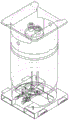
Fig. 4 is a front view of a vertical ton tank according to one embodiment.
Fig. 5 is a side view of a vertical ton tank according to one embodiment.
Fig. 6A is a deployed front view of the internal piping of the vertical ton tank, according to one embodiment.
Fig. 6B is an expanded side view of the inner pipe of the vertical ton tank according to one embodiment.
Fig. 7 shows a pipe coupling of a vertical ton tank according to an embodiment.
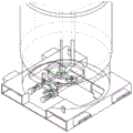
Fig. 8 is a view of a bottom portion of a vertical ton tank according to one embodiment.
Fig. 9 is an expanded top view of a valve configuration of the vertical ton tank according to one embodiment.
Fig. 10 is an expanded side view of a valve configuration of a vertical ton tank in accordance with one embodiment.
Fig. 11 is a view of a vertical ton tank having a bottom protective gasket according to one embodiment.
Fig. 12 shows a door as part of a bottom protective gasket for a vertical ton can, according to one embodiment.
Wherever possible, the same reference numbers will be used throughout the drawings to refer to the same or like parts.
Detailed Description
The present invention provides methods for recovering, recycling and regenerating deteriorated or used refrigerant. Embodiments of the present disclosure include, for example, recovering a refrigerant composition from a point of use, testing the refrigerant composition to determine impurities, modifying a characteristic of the refrigerant composition above a predetermined threshold, and transferring the refrigerant composition to the point of use.
The refrigerant regeneration system 100 is depicted in fig. 1. In the example of fig. 1, a source tank 110 containing an unreregenerated refrigerant composition 115 is communicatively connected to a receiver tank 120 and is configured to allow some or all of the unreregenerated refrigerant composition 115 to be transferred to the receiver tank 120. One or more samples of the unreregenerated refrigerant composition 115 may be collected from the source tank 110 or the receiver tank 120, or a combination thereof. The sample may be analyzed to determine the content of one or more components in the unreduced refrigerant composition 115. The content of one or more components may cause the unreregenerated refrigerant composition 115 to be outside of desired compositional specifications. In some embodiments, the unreregenerated refrigerant composition 115 may be a non-azeotropic composition. In other embodiments, the unreregenerated refrigerant composition 115 may be an azeotropic composition.
In some embodiments, the unreregenerated refrigerant composition 115 may comprise components resulting from the polymerization or decomposition of one or more hydrofluoroolefin refrigerants. In some embodiments, the component may comprise a polymer, oligomer, phthalate, adipate, fluorinated hydrocarbon, or other reaction product. In one embodiment, the unreregenerated refrigerant composition may comprise a homopolymer resulting from polymerization of one or more refrigerant components of the unreregenerated refrigerant composition 115. In some embodiments, the non-regenerated refrigerant composition 115 may include an acid component that may reduce the cycle performance of the non-regenerated refrigerant composition 115. In some embodiments, the non-regenerated refrigerant composition 115 may include chlorine-containing or oxidizing species that may be harmful to refrigeration system components such as hoses, gaskets, or fittings. In some embodiments, the unreregenerated refrigerant composition 115 may include other components, such as water, oil (e.g., mineral oil or polyol ester), or dyes.
The presence and concentration of various components of the unreregenerated refrigerant composition 115 can be analyzed using various analytical techniques including gas chromatography, mass spectrometry, infrared spectroscopy, moisture content, acid content, non-condensables content, high boiling residue, and/or color measurements. If the content of one or more components is outside of one or more predetermined thresholds for the components, a treatment plan (or schedule) for the unreregenerated refrigerant composition 115 is determined.
The treatment plan includes the step of changing the composition of the unreduced refrigerant composition 115 to meet the target composition. The treatment plan may include one or more treatments of the unreregenerated refrigerant composition 115. In some embodiments, the target composition is a refrigerant composition suitable for regeneration in a refrigeration system that meets composition specifications. In some embodiments, the target composition comprises at least one of 2, 3, 3, 3-tetrafluoropropene (HFO-1234yf) or trans-1, 3, 3, 3-tetrafluoro-1-propene (HFO-1234ze (e)). In some embodiments, the target composition comprises 2, 3, 3, 3-tetrafluoropropene (HFO-1234yf) or trans-1, 3, 3, 3-tetrafluoro-1-propene (HFO-1234ze (e)) in an amount of at least equal to or greater than 99.5% of the refrigerant composition.
In some embodiments, one or more of the refrigerants of the unreregenerated refrigerant composition 115 may be a flammable refrigerant. By flammable is meant a gas having a flammable Concentration range in air at 60 degrees Celsius and a pressure of 101.3 kilopascals according to ASTM E-681-09-Standard Test Method for Concentration of flexibility of Chemicals (Vapors and Gases).
Vertical ton pot (VTT)
In one embodiment, one aspect of the process is the use of a convenient vessel that can easily recover, recycle, and regenerate the used refrigerant. In the exemplary embodiments described herein, the vessel is a 500L to 1000L, or more specifically 750L to 950L, or more specifically 850L to 950L vertical cylinder designed to hold, transfer, or transport the flammable composition during recovery, recirculation, and regeneration, and which is adapted to ease handling of the used refrigerant due to the vertical orientation. It should be noted that any vertical cylinder designed for flammable refrigerants may also be conveniently used for non-flammable refrigerants. The Vertical Ton Tank (VTT) of the present invention has specific design parameters which in the combination described below make it uniquely useable in conjunction with the other regeneration processes mentioned above. One or more vertical ton tanks may be used in refrigeration distribution system 100 for different purposes, including as source tank 110 and/or receiving tank 120.
Orientation of
VTT cylinders are designed such that the pressure vessel is vertically oriented, which means that the cylinder is upright (vertical) during use, transport and storage. Since the footprint (m2) may be limited near recovery/recycle/refill (R/R) operations, the particular orientation is suitable for smaller physical footprints at potential recovery locations. In addition, the vertically oriented design lends itself advantageously to the actual transportation of vertical ton tanks. The vertical ton tank can be conveniently loaded onto a forklift without losing any gravity or positioning unusually as is the case with the horizontal ton tank. The design of the base of the vertical ton tank is also designed to improve product transport. In one design option, the bottom of the vertical ton tank has an integrated pallet with openings for the forklift tines. Thus, the VTT may be safely and conveniently used to physically move flammable refrigerants to a remote recovery processing location.
Depending on the refrigerant used in the R/R/R process, the pressure, flammability, and volume will follow the appropriate design codes. For example, in the united states, the vertical ton tank will follow the ASME design configuration and pressure rating, while in EU, the vertical ton tank will follow ADR, and in japan, the vertical ton tank will follow HPGL.
Dip tube orientation
Another embodiment of the improved VTT is the position and orientation of the dip tube. While the dip tube is essential to the cylinder design, the combination of the position of the dip tube and flange and the orientation in which the dip tube meets the upper and lower flanges provides unique product delivery for the R/R of the refrigerant used, as discussed in the next section. Fig. 4 and 5 show front and side views of an embodiment of a Vertical Ton Tank (VTT) with a dip tube. Dip tubes 62 and 65 are shown with 1/2 inch and 1 inch connections at the top and bottom of the tank. The attachment of dip tubes 62 and 65 to top flange 60 and bottom flange 61 is also depicted. Of note are the dip tube orientations of #62 and #65 and how they fit with the top and bottom flanges.
Bottom flange and top flange
Another embodiment of the utility of the redesigned VTT is the addition and positioning of flanges, which also facilitates the R/R/R process. While process refrigerant may be transported from the VTT to another VTT or a separate storage container, it is desirable to be able to enter the VTT to see which residues are left in the VTT. Therefore, the VTT is designed to include two larger flanges labeled (top flange 60) and (bottom flange 61). The bottom and top flanges facilitate opening of the VTT can and visual or easy inspection by a peep procedure, such as a borescope. The flange also helps to easily remove any debris that may have collected from the used refrigerant contaminants. The flange is shown in fig. 4 and 5.
Pipe from flange to valve
Another embodiment in redesigning the VTT is from the flange to the valve location and design piping/connections. As can be seen in the figures, the bottom flange has larger and smaller discharge pipes from the flange. Figure 6 shows the position and orientation of the discharge pipe.
Fig. 7 and 8 are an expanded top view and side view of the bottom portion of the (VTT). These figures show the elements in more detail and how they are arranged into the main bottom flange. The smaller conduit details are given in the elements 83, 84, 85 (smaller flanges) which are connected to 1/2' conduit 64 which then leads to the connector. Greater conduit details are given in elements 87, 88 and 89 connected to the 1' conduit 63.
Parts list

Gasket ring
Another design factor is the addition of a PTFE gasket as shown, which ensures that there is no additional contamination from the gasket. PTFE gaskets have been found to be non-hazardous to HFO type products and therefore need to be used in combination with this design.
Valve with a valve body
Another unique design factor is the addition of a Dry Bulk Coupler (DBC) which limits the amount of refrigerant that can be released during refrigerant transfer. The dry bulk coupler has a special locking mechanism that stops product transfer until an unlocking mechanism is engaged. After the unlocking mechanism is engaged, the product is transferred. This mechanism reduces the release of combustible products to less than 1 gram and is highly desirable in the VTT design. The DBC also contributes to a sustainable transport of refrigerant, since less than one gram of refrigerant is typically released during coupling and decoupling of the DBC. The combination of DBC with the process facilitates ease of product transfer, increases safety and containment, and any inadvertent exposure to refrigerants and/or contaminants. These are elements 122, 124 and 125 in the drawing. The adapter from the metal conduit to the DBC is element 123. DBC brands are commonly referred to as Denver Gardner TODO, Econosto valves, and Dixon valves.
Bottom lining picture
A specially designed VTT has a bottom collar that latches into place to protect a bottom valve associated with the VTT. The collar prevents the forklift tines from potentially hitting the lower valve and/or flange, thereby protecting the product. In addition, the bottom gasket can be zipper-tied to facilitate anti-counterfeiting detection. Any breach of the certified zip lock may indicate that the product has been potentially tampered with.
See fig. 9, which shows how the collar fits over the valve. Figure 10 shows a protective gate that can further protect the valve when the tank is not externally connected.
In the example of fig. 1, the unreregenerated refrigerant composition 115 may be transferred from the receiver tank 120 to the processing unit 130. The process unit 130 includes one or more process modules that act on the non-regenerated refrigerant composition 115 to reduce the concentration of one or more non-regenerated refrigerant composition 115 components below one or more predetermined thresholds for the non-regenerated refrigerant composition 115. In some embodiments, the unreregenerated refrigerant composition 115 may be treated by a first treatment to form a partially regenerated refrigerant composition.
In one embodiment, the processing unit 130 includes a blend module 131. Blend module 131 adds a composition to the un-regenerated refrigerant composition 115 or the partially regenerated refrigerant composition to alter the concentration of one or more components. The change may result in the concentration of one or more components being changed to less than one or more predetermined thresholds for the unreregenerated refrigerant composition 115. In some embodiments, the purity of the regenerated refrigerant composition will be greater than 99.5 weight percent, based on the total weight of the refrigerant composition.
In one embodiment, the processing unit 130 includes a transfer module 132. The transfer module 132 transfers at least a portion of the non-regenerated refrigerant composition 115 or the partially regenerated refrigerant composition to the regeneration tank. The transfer of refrigerant composition results in a change in the concentration of one or more components of the unreregenerated refrigerant composition 115. In some embodiments, the transfer partially fills the regeneration tank.
In some embodiments, a method for filling a refrigerant mixture comprising a non-azeotropic (or azeotropic) refrigerant into a regeneration tank includes adjusting a ratio of at least one component of a refrigerant composition in a liquid phase of the refrigerant mixture to a particular range prior to transferring. In some embodiments, the refrigerant composition may be treated by the blend module 131 before being treated by the transfer module 132.
The mixture ratio is described below in terms of a partially regenerated refrigerant composition or an unreregenerated refrigerant composition 115 prior to transfer from a refrigerant composition source filled with a refrigerant composition in an amount less than 100 weight percent of the maximum fill of the refrigerant mixture.
The term "maximum fill volume" (100% by weight of the maximum fill volume) as used herein refers to the maximum volume that can be filled into a container as defined by regulatory agencies such as the U.S. department of transportation (US DOT), european union ADR, european agreements on road international transport of hazardous goods (ADR), and japanese high pressure natural gas safety act. According to these transportation regulations, the maximum fill quantity is calculated as follows:
G=V/C
g: mass (kg) of fluorocarbon compound
V: capacity of container (L)
C: according to the type of fluorocarbon filled into the container and the constant of the temperature or pressure limit defined in the regulations.
When the non-regenerated refrigerant composition 115 partially fills the regeneration vessel, a portion of each component vaporizes to fill the remaining space within the regeneration vessel. For non-azeotropic compositions, the relative proportion of the lower boiling component in the vapor is greater than the proportion of the lower boiling component in the non-regenerated refrigerant composition 115 that is liquid. Thus, the ratio of the lower boiling component relative to the higher boiling component of the unrejuvenated refrigerant composition as a liquid is varied by the transfer.
In some embodiments, the target composition comprises a non-azeotropic composition. In some embodiments, the target composition comprises at least one major component. The unreregenerated refrigerant composition 115 may also include at least one minor component in addition to the at least one major component. In some embodiments, at least one major component is a desired material of a target composition. In some embodiments, at least one of the minor components is an undesired component of the target composition. In some embodiments, the at least one minor component may exhibit a lower boiling point than the at least one major component. During processing by the transfer module 132, the ratio of the at least one major component to the at least one minor component may be increased based on the unrenewed refrigerant composition 115 as a liquid.
In one embodiment, the processing unit 130 includes a decant module 133. Decant module 133 can separate one or more immiscible materials from the partially regenerated refrigerant composition or the non-regenerated refrigerant composition 115. For example, decant module 133 may separate the immiscible liquids by pumping and/or draining one or more liquids out of decant module 132. In one embodiment, the separated liquid is an impurity, and thus is separated from the non-regenerated refrigerant composition 115 remaining in the decant module 133. In one embodiment, the separated liquid may comprise the desired refrigerant composition, thus separating the desired material from the one or more impurities remaining in the decant module 132. Decantation may result in the concentration of one or more components being changed to less than one or more predetermined thresholds for the non-regenerated refrigerant composition 115. In one embodiment, the ratio of the at least one major component to the at least one minor component may be increased based on the unreformed refrigerant composition 115 as a liquid. In some embodiments, the concentration of non-condensable materials may be varied to achieve a concentration of less than 1.5 volume percent at 25 degrees celsius according to AHRI700 (air conditioning, heating and refrigeration association standard, "specificities for Fluorocarbon reflagers," AHRI700, 2016 for 9 months). In some embodiments, the purity of the regenerated refrigerant composition will be greater than 99.5 weight percent, based on the total weight of the refrigerant composition.
In one embodiment, the processing unit 130 includes a distillation module 133. The distillation module 134 may separate one or more materials from the partially regenerated refrigerant composition or the non-regenerated refrigerant composition 115. For example, the distillation module 134 may separate one or more impurities from the unreregenerated refrigerant composition 115 by distilling one or more materials from the distillation module 134. In one embodiment, the separated material is an impurity, and thus is separated from the unreregenerated refrigerant composition 115 remaining in the distillation module 134. In one embodiment, the separated material may comprise a desired refrigerant composition, thus separating the desired material from one or more impurities remaining in distillation module 134. The distillation may result in the concentration of one or more components being changed to be less than one or more predetermined thresholds of the unreduced refrigerant composition 115. In one embodiment, the ratio of the at least one major component to the at least one minor component may be increased based on the unreformed refrigerant composition 115 as a liquid. In some embodiments, the concentration of non-condensable materials may be varied to give a concentration of less than 1.5 volume percent at 25 degrees celsius according to AHRI 700. In some embodiments, the purity of the regenerated refrigerant composition will be greater than 99.5 weight percent, based on the total weight of the refrigerant composition.
In one embodiment, the processing unit 130 includes a filtering module 135. The filtration module 135 may separate one or more insoluble particles from the partially regenerated refrigerant composition or the non-regenerated refrigerant composition 115. For example, the filtration module 135 may separate the plurality of insoluble particles from the non-regenerated refrigerant composition 115 by filtration. In some embodiments, the unreregenerated refrigerant composition 115 is filtered through a screen of at least 0.01 microns, a screen of at least 0.03 microns, a screen of at least 0.05 microns, a screen of at least 0.08 microns, a screen of at least 0.1 microns, or a screen of at least 0.15 microns. In one embodiment, the unreregenerated refrigerant composition 115 is filtered through a 0.1 micron screen. Filtering may result in the concentration of one or more components being changed to be less than one or more predetermined thresholds for the unreregenerated refrigerant composition 115. In one embodiment, the ratio of the at least one major component to the at least one minor component may be increased based on the unreformed refrigerant composition 115 as a liquid. In one embodiment, the concentration of one or more components may be varied to give an oil concentration of less than 0.5 weight percent, but preferably less than 0.05 weight percent, and even more preferably less than 0.0025 weight percent, less than 22 parts per million parts by weight (ppm). In one embodiment, the concentration of one or more components may be varied, resulting in a reduction in the concentration of the dye. In one embodiment, the color of the unreproduced refrigerant composition 115 is changed to a Gardner color value of less than 3.
In one embodiment, the processing unit 130 includes a washing module 136. The washing module 136 can treat the non-regenerated refrigerant composition 115 by contacting the non-regenerated refrigerant composition 115 with a treatment composition. In some embodiments, the treatment composition may be a caustic (alkaline) detergent. For example, the scrubbing module 136 may contact the non-regenerated refrigerant composition 115 with a caustic solution to remove components including an acid portion. In one embodiment, the unreregenerated refrigerant composition 115 is contacted with an aqueous sodium hydroxide solution using a venturi scrubber. The washing may result in the concentration of one or more components being changed to less than one or more predetermined thresholds for the unreregenerated refrigerant composition 115. In one embodiment, the concentration of one or more components may be varied to provide a Total Acid Number (TAN) of less than 2 mg KOH per 2 grams of the unrenewed refrigerant composition 115. In one embodiment, the concentration of one or more components may be varied to achieve an acidity level of less than 1ppm by weight based on AHRI 700. In some embodiments, the resulting washed non-regenerated refrigerant composition 115 may be further collected and dried to remove any residual water.
In one embodiment, processing unit 130 includes a dehydration module 137. The dehydration module 137 may be used to remove water from the non-regenerated refrigerant composition 115. For example, the dehydration module 137 may contact the non-regenerated refrigerant composition 115 with a desiccant such as molecular sieve. Dehydration may result in a decrease in the concentration of one or more impurities to less than one or more predetermined thresholds for the unreregenerated refrigerant composition 115. In one embodiment, the washed non-regenerated refrigerant composition 115 may be dehydrated by passing the washed non-regenerated refrigerant composition 115 through a dehydration module 137. In some embodiments, the moisture concentration may be varied to result in a moisture content of less than 20ppm by weight per AHRI 700. In one embodiment, the moisture concentration may be varied to achieve a moisture content of less than 10ppm by weight based on the AHRI700 or less than 5ppm by weight based on the AHRI 700.
In one embodiment, the process unit 130 includes an inert gas purge module 138. The inert gas purge module 138 may contact the non-regenerated refrigerant composition 115 with an inert gas, such as nitrogen, argon, or xenon, to displace dissolved reactive gases in the non-regenerated refrigerant composition 115. In one embodiment, the inert gas may comprise dry nitrogen. The inert gas purge may result in the concentration of one or more components being changed to less than one or more predetermined thresholds for the unreregenerated refrigerant composition 115. In one embodiment, the concentration of non-condensable gases (NCG) or non-absorbable gases (NAG) may be varied to give a concentration of less than 1.5 vol% at 25 degrees celsius according to AHRI700, preferably less than 0.9 vol% at 25 degrees celsius according to AHRI 700. NAG typically contains air (which typically consists of 78% nitrogen, 21% oxygen, and about 1% argon) that accumulates in the refrigerant gas phase, where the solubility of air in the refrigerant liquid phase is extremely low. While it may be important to reduce the total amount of NAG contained in the refrigerant, it is generally more desirable to reduce the oxygen-containing fraction of NAG in preference to the nitrogen fraction. In some cases, the oxygen-containing moieties can increase the tendency of the refrigerant to decompose or form undesirable polymeric materials.
In one embodiment, the processing unit 130 includes a non-absorbable gas (NAG) reduction unit 139.
The NAG reduction unit 139 can contact the non-regenerated refrigerant composition with a reducing agent, such as a metal powder, that can react with the oxygen or other oxidizable component of the non-regenerated refrigerant composition. In one embodiment, the reducing agent may comprise iron powder. The processing by the NAG reduction unit 139 may result in a decrease in the concentration of one or more components of the unreduced refrigerant composition to less than one or more predetermined thresholds for the unreduced refrigerant composition. In one embodiment, the concentration of non-condensable materials may be varied to give a concentration of less than 1.5 volume percent at 25 degrees celsius according to AHRI700, preferably less than 0.9 volume percent at 25 degrees celsius according to AHRI 700.
In another embodiment, the condenser is used in conjunction with a cooling medium that is cold enough to condense the refrigerant and pass the NAG with minimal loss of refrigerant. A compressor may be used in conjunction with a condenser to increase pressure and make it easier to condense refrigerant at higher temperatures.
And in even another embodiment, the membrane is placed such that the NAG can pass through the membrane and be removed while the refrigerant does not pass, thus the NAG is separated from the refrigerant.
The modules of the processing unit 130 may be used alone or in combination. The unreregenerated refrigerant composition 115 may be processed one or more times by any of the modules of the processing unit 130. The one or more treatments performed by the one or more modules of the treatment unit 130 may result in the unreregenerated refrigerant composition 115 becoming a regenerated refrigerant composition in which all concentrations of the one or more impurities are reduced to less than one or more predetermined thresholds. In some embodiments, the regenerated refrigerant composition will exhibit impurity levels equivalent to the virgin material. In some embodiments, the purity of the regenerated refrigerant composition will be greater than 99.5 weight percent, based on the total weight of the refrigerant composition. In some embodiments, the purity of the regenerated refrigerant composition will be greater than 99.7 weight percent, based on the total weight of the refrigerant composition. In some embodiments, the purity of the regenerated refrigerant composition will be greater than 99.9 wt.%, based on the total weight of the refrigerant composition.
As shown in fig. 1, the regenerated refrigerant composition may be transferred from the process unit 130 to the use tank 140. The use tank 140 may contain both regenerated and unused materials. The usage tank 140 may be directly connected to the refrigeration system and configured to supply refrigerant to the refrigeration system. Alternatively, the use tank 140 may be connected to the distribution tank 150. The use of tank 140 can supply refrigerant to a generally smaller distribution tank 150. Thereafter, the distribution tank 150 may be transported to a point of use and used to supply refrigerant to a refrigeration system or a customer's storage tank. In some embodiments, the refrigerant composition using the tank 140 or the distribution tank 150 will have a purity of greater than 99.5 weight percent, based on the total weight of the refrigerant composition. In some embodiments, the refrigerant composition using the tank 140 or the distribution tank 150 will have a purity of greater than 99.7 weight percent, based on the total weight of the refrigerant composition. In some embodiments, the refrigerant composition using the tank 140 or the distribution tank 150 will have a purity of greater than 99.9 weight percent, based on the total weight of the refrigerant composition.
In some embodiments, an additive may be added to the regenerated refrigerant composition. In one embodiment, the additive is present at a concentration of less than 0.4 weight percent based on the regenerated refrigerant composition. In one embodiment, the additive may comprise an inhibitor. In one embodiment, the inhibitor may comprise at least one of limonene, alpha-terpinene, alpha-tocopherol, butylated hydroxytoluene, 4-methoxyphenol, or benzene-1, 4-diol. In one embodiment, the inhibitor comprises a material having a melting point at a temperature of-70 degrees celsius to 180 degrees celsius.
In some embodiments, the regenerated refrigerant composition may comprise one or more optional non-refrigerant components selected from the group consisting of lubricants, dyes (including UV dyes), solubilizers, compatibilizers, stabilizers, tracers, antiwear agents, extreme pressure agents, corrosion and oxidation inhibitors, metal surface energy reducers, metal surface deactivators, free radical scavengers, foam control agents, viscosity index improvers, pour point depressants, detergents, viscosity modifiers, and mixtures thereof. In some embodiments, the optional non-refrigerant components may be referred to as additives. Indeed, many of these optional non-refrigerant components fit into one or more of these categories and may have qualities that enable them to achieve one or more performance characteristics themselves.
In some embodiments, one or more non-refrigerant components are present in minor amounts relative to the overall composition. In some embodiments, the concentration of the additive in the disclosed compositions is in an amount of less than about 0.1% by weight up to about 5% by weight of the total composition. In some embodiments of the invention, the additive is present in the disclosed compositions in an amount between about 0.1% to about 5% by weight of the total composition or in an amount between about 0.1% to about 3.5% by weight. In one embodiment, the additive is present at a concentration of less than 0.4 weight percent based on the regenerated refrigerant composition. The additive components selected for use in the disclosed compositions are selected based on utility and/or individual equipment component or system requirements.
In one embodiment, the lubricant is selected from the group consisting of mineral oils, alkylbenzenes, polyol esters, polyalkylene glycols, polyvinyl ethers, polycarbonates, perfluoropolyethers, silicones, silicates, phosphates, paraffins, naphthenes, polyalphaolefins, and combinations thereof.
The lubricants disclosed herein may be commercially available lubricants. For example, the lubricant may be a paraffinic mineral oil sold by BVA Oils as BVM 100N; naphthenic mineral oils, by Crompton Co 1GS、
1GS、 3GS and
 5GS is sold; naphthenic mineral oil, tradename of Pennzoil
 372LT sale; naphthenic mineral oils, tradename of Calumet Lubricants
 Selling RO-30; linear alkylbenzenes, sold under the trade name by Shrieve Chemicals
 75、
75、 150 and
 500, selling; and branched alkylbenzenes sold by Nippon Oil as HAB 22; polyol esters (POE),
 trade name
100 sold by Castrol, United Kingdom; polyalkylene glycols (PAGs), such as RL-488A, available from Dow (Dow Chemical, Midland, Michigan); and mixtures thereof (meaning mixtures of any of the lubricants disclosed in this paragraph).
In the compositions of the present invention comprising a lubricant, the lubricant is present in an amount of less than 40.0 wt.%, relative to the total composition. In other embodiments, the amount of lubricant is less than 20% by weight of the total composition. In other embodiments, the amount of lubricant is less than 10% by weight of the total composition. In other embodiments, the amount of lubricant is between about 0.1% and 5.0% by weight of the total composition.
Notwithstanding the above weight ratios of the compositions disclosed herein, it should be understood that in some heat transfer systems, additional lubricant may be taken from one or more equipment components of such heat transfer systems where the compositions are used. For example, in some refrigeration, air conditioning, and heat pump systems, lubricant may be charged to the compressor and/or the compressor lubricant sump. Such lubricants, in addition to any lubricant additives, will be present in the refrigerant of such systems. In use, the refrigerant composition may take an amount of the apparatus lubricant while in the compressor to vary the refrigerant-lubricant composition from an initial ratio.
The non-refrigerant components used with the compositions of the present invention may include at least one dye. The dye may be at least one Ultraviolet (UV) dye. The UV dye may be a fluorescent dye. The fluorescent dye may be selected from the group consisting of naphthalimides, perylenes, coumarins, anthracenes, phenanthrenes, xanthenes, thioxanthenes, benzoxanthenes, fluorescein, and derivatives of said dyes, and combinations thereof (meaning mixtures of any of the foregoing dyes or derivatives thereof disclosed in this paragraph).
In some embodiments, the disclosed compositions comprise from about 0.001% to about 1.0% by weight of a UV dye. In other embodiments, the UV dye is present in an amount from about 0.005 wt% to about 0.5 wt%; and in other embodiments, the UV dye is present in an amount of from 0.01% to about 0.25% by weight of the total composition.
UV dyes are useful components for detecting leaks in compositions by allowing fluorescence of the dye at or near the point of leak in a viewing device, such as a refrigeration unit, air conditioner or heat pump. UV emission, such as fluorescence of a dye, can be observed under ultraviolet light. Thus, if a composition containing such a UV dye leaks from a given point in the device, fluorescence can be detected at or near the leak.
Another non-refrigerant component that may be used with the compositions of the present invention may include at least one solubilizing agent selected to improve the solubility of one or more dyes in the disclosed compositions. In some embodiments, the weight ratio of dye to solubilizer ranges from about 99: 1 to about 1: 1. The solubilizing agent comprises at least one compound selected from the group consisting of: hydrocarbons, hydrocarbon ethers, polyoxyalkylene glycol ethers (such as dipropylene glycol dimethyl ether), amides, nitriles, ketones, chlorocarbons (such as methylene chloride, trichloroethylene, chloroform, or mixtures thereof), esters, lactones, aromatic ethers, fluoroethers, and 1, 1, 1-trifluoroalkanes and mixtures thereof (meaning mixtures of any of the solubilizing agents disclosed in this paragraph).
In some embodiments, the non-refrigerant component comprises at least one compatibilizer to improve the compatibility of one or more lubricants with the disclosed compositions. The compatibilizer may be selected from hydrocarbons, hydrocarbon ethers, polyoxyalkylene glycol ethers (such as dipropylene glycol dimethyl ether), amides, nitriles, ketones, chlorocarbons (such as methylene chloride, trichloroethylene, chloroform, or mixtures thereof), esters, lactones, aromatic ethers, fluoroethers, 1, 1, 1-trifluoroalkanes, and mixtures thereof (meaning mixtures of any of the compatibilizers disclosed in this paragraph).
The solubiliser and/or compatibiliser may be selected from hydrocarbon ethers consisting of ethers containing only carbon, hydrogen and oxygen, such as dimethyl ether (DME) and mixtures thereof (meaning mixtures of any of the hydrocarbon ethers disclosed in this paragraph).
The compatibilizer may be a linear or cyclic aliphatic or aromatic hydrocarbon compatibilizer containing 3 to 15 carbon atoms. The compatibilizer can be at least one hydrocarbon that can be selected from at least one of propane (including propylene and propane), butane (including n-butane and isobutylene), pentane (including n-pentane, isopentane, neopentane, and cyclopentane), hexane, octane, nonane, and decane, among others. Commercially available hydrocarbon compatibilizers include, but are not limited to, those under the trade names H those sold by Exxon Chemical (USA), undecane (C)11) With dodecane (C)12) Mixture of (2) (high purity C)11To C12Isoparaffin), Aromatic 150 (C)9To C11Aromatic), Aromatic 200 (C)9To C15Aromatic) and Naptha 140 (C)5To C11Mixtures of paraffins, naphthenes and aromatics), and mixtures thereof (meaning mixtures of any of the hydrocarbons disclosed in this paragraph).
The compatibilizer may alternatively be at least one polymeric compatibilizer. The polymeric compatibilizer may be a random copolymer of fluorinated and non-fluorinated acrylates wherein the polymer comprises a copolymer having the formula CH2=C(R1)CO2R2、CH2=C(R3)C6H4R4And CH2=C(R5)C6H4XR6Repeating units of at least one monomer represented by (a) wherein X is oxygen or sulfur; r1、R3And R5Independently selected from H and C1-C4An alkyl group; and R is2、R4And R6Independently selected from carbon chain based groups containing C and F, and may also contain H, Cl, ether oxygen, or sulfur in the form of a thioether, sulfoxide or sulfone group, and mixtures thereof. Examples of such polymeric compatibilizers include those available under the trade name PHS is commercially available from E.I.du Pont DE Nemours and Company, (Wilmington, DE, 19898, USA).
 PHS is a random copolymer prepared by polymerizing: 40% by weight of CH2=C(CH3)CO2CH2CH2(CF2CF2) mF (also known as
 Fluoro methacrylate or ZFM), wherein m is 1 to 12, mainly 2 to 8, and 60% by weight of lauryl methacrylate (CH)2=C(CH3)CO2(CH2)11CH3Also known as LMA).
In some embodiments, the compatibilizer component comprises about 0.01 to 30 weight percent (based on the total amount of compatibilizer) of an additive that reduces the surface energy of metallic copper, aluminum, steel, or other metals and their metal alloys present in the heat exchanger in a manner that reduces the adhesion of the lubricant to the metal. Examples of metal surface energy reducing additives include FSA、
FSA、 FSP and
 FSJ is those commercially available from DuPont.
Another optional non-refrigerant component that may be used with the compositions of the present invention may be a metal surface deactivator. The metal surface deactivators are selected from the group consisting of oxalyl bis (benzylidene) hydrazide (CAS registry No. 6629-10-3), N ' -bis (3, 5-di-tert-butyl-4-hydroxyhydrocinnamate (CAS registry No. 32687-78-8), 2 ' -oxamido bis-ethyl- (3, 5-di-tert-butyl-4-hydroxyhydrocinnamate (CAS registry No. 70331-94-1), N ' - (disalicylidene) -1, 2-diaminopropane (CAS registry No. 94-91-7), and ethylenediaminetetraacetic acid (CAS registry No. 60-00-4) and salts thereof, and mixtures thereof (meaning mixtures of any of the metal surface deactivators disclosed in this paragraph).
The optional non-refrigerant component used with the composition of the present invention may alternatively be a stabilizer selected from the group consisting of: hindered phenols, thiophosphates, butylated triphenyl thiophosphate, organophosphates, or phosphites, arylalkyl ethers, terpenes, terpenoids, epoxides, fluorinated epoxides, oxetanes, ascorbic acid, thiols, lactones, thioethers, amines, nitromethane, alkylsilanes, benzophenone derivatives, aryl thioethers, divinyl terephthalic acid, diphenyl terephthalic acid, ionic liquids, and mixtures thereof (meaning mixtures of any of the stabilizers disclosed in this paragraph).
The stabilizer may be selected from: a tocopherol; hydroquinone; tert-butyl hydroquinone; a monothiophosphate ester; and dithiophosphoric acid esters, trade names 63 is commercially available from Ciba Specialty Chemicals (Basel, Switzerland) (hereinafter "Ciba"); dialkyl thiophosphates, respectively trade name
 353 and
 350 is commercially available from Ciba; butylated Triphenyl thiophosphate, trade name
 232 commercially available from Ciba; amine phosphates, trade name
 349(Ciba) is commercially available from Ciba; hindered phosphite salts of
 168 commercially available from Ciba, and tris- (di-t-butylphenyl) phosphite, under the trade name
 OPH is commercially available from Ciba; (di-n-octyl phosphite); and isodecyl diphenyl phosphite, trade name
 DDPP is commercially available from Ciba; trialkyl phosphates such as trimethyl phosphate, triethyl phosphate, tributyl phosphate, trioctyl phosphate, and tris (2-ethylhexyl) phosphate; triaryl phosphates including triphenyl phosphate, tricresyl phosphate, and trixylenyl phosphate; and mixed alkyl-aryl phosphates including isopropyl phenyl phosphate (IPPP) and bis (tert-butylphenyl) phenyl phosphate (TBPP); butylated triphenyl phosphate, such as that sold under the trade name
 Those commercially available, including
 8784; tert-butylated triphenyl phosphate, such as that sold under the trade name
 620 those commercially available; isopropylated triphenyl phosphates, such as those sold under the tradename
 220 and
 110 those commercially available; anisole; 1, 4-dimethoxybenzene; 1, 4-diethoxybenzene; 1, 3, 5-trimethoxybenzene; myrcene, alloocine, limonene (especially d-limonene); retinal; pinene; menthol; geraniol; farnesol; phytol; a vitamin A; terpinene; delta-3-carene; terpinolene; phellandrene; fenchylene; dipentene; carotenoids such as lycopene, beta carotene, and xanthophylls such as zeaxanthin; retinoids, such as hepatic lutein and isotretinoin; camphane; 1, 2-propylene oxide; 1, 2-butylene oxide; n-butyl glycidyl ether; trifluoromethyl oxirane; 1, 1-bis (trifluoromethyl) oxirane; 3-ethyl-3-hydroxymethyl-oxetane, such as OXT-101(Toagosei co., Ltd); 3-ethyl-3- ((phenoxy) methyl) -oxetane, such as OXT-211(Toagosei co., Ltd); 3-ethyl-3- ((2-ethyl-hexyloxy) methyl) -oxetane, such as OXT-212(Toagosei co., Ltd); ascorbic acid; methyl mercaptan (methyl mercaptan); ethanethiol (ethyl mercaptan); coenzyme A; dimercaptosuccinic acid (DMSA); grapefruit mercaptan ((R) -2- (4-methylcyclohex-3-enyl) propane-2-thiol)); cysteine ((R) -2-amino-3-sulfonyl-propionic acid); lipoamide (1, 2-dithiolane-3-pentanamide); 5, 7-bis (1, 1-dimethylethyl) -3- [2, 3 (or 3, 4) -dimethylphenyl]-2(3H) -benzofuranone, trade name
 HP-136 is commercially available from Ciba; benzylphenylsulfide; diphenyl sulfide; diisopropylamine; dioctadecyl 3, 3' -thiodipropionate, known under the trade name
 PS 802(Ciba) is commercially available from Ciba(ii) a 3, 3' -Didodecyl thiopropionate, trade mark
 PS 800 is commercially available from Ciba; bis- (2, 2, 6, 6-tetramethyl-4-piperidyl) sebacate, trade name
 770 commercially available from Ciba; succinic acid poly- (N-hydroxyethyl-2, 2, 6, 6-tetramethyl-4-hydroxy-piperidyl ester, trade name
 622LD (Ciba) is commercially available from Ciba; methyl ditallowamine; ditalloxamine; phenol- α -naphthylamine; bis (dimethylamino) methylsilane (DMAMS); tris (trimethylsilyl) silane (TTMSS); vinyltriethoxysilane; vinyl trimethoxysilane; 2, 5-difluorobenzophenone; 2 ', 5' -dihydroxyacetophenone; 2-aminobenzophenone; 2-chlorobenzophenone; benzylphenylsulfide; diphenyl sulfide; dibenzyl sulfide; an ionic liquid; and mixtures and combinations thereof.
The optional non-refrigerant component used with the composition of the present invention may alternatively be an ionic liquid stabilizer. The ionic liquid stabilizer may be selected from organic salts that are liquid at room temperature (about 25 ℃), those salts comprising a cation selected from pyridinium, pyridazinium, pyrimidinium, pyrazinium, imidazolium, pyrazolium, thiazolium, oxazolium, and triazolium, and mixtures thereof; and is selected from [ BF4]-、[PF6]-、[SbF6]-、[CF3SO3]-、[HCF2CF2SO3]-、[CF3HFCCF2SO3]-、[HCClFCF2SO3]-、[(CF3SO2)2N]-、[(CF3CF2SO2)2N]-、[(CF3SO2)3C]-、[CF3CO2]-and F-and mixtures thereof. In some embodiments, the ionic liquid stabilizer is selected from emim BF4(1-Ethyl-3-methylimidazoleOxazoltetrafluoroborate); bmim BF4(1-butyl-3-methylimidazole tetraborate); emim PF6(1-ethyl-3-methylimidazolium hexafluorophosphate); and bmim PF6(1-butyl-3-methylimidazolium hexafluorophosphate), all of which were purchased from Fluka (Sigma-Aldrich).
In some embodiments, the stabilizer may be a hindered phenol, which is any substituted phenol compound, including phenols comprising one or more substituted or cyclic, linear, or branched aliphatic substituents, such as alkylated monophenols, including 2, 6-di-tert-butyl-4-methylphenol; 2, 6-di-tert-butyl-4-ethylphenol; 2, 4-dimethyl-6-tert-butylphenol; a tocopherol; and the like; hydroquinone and alkylated hydroquinones including tert-butyl hydroquinone, other derivatives of hydroquinone; and the like; hydroxylated thiodiphenyl ethers, including 4, 4' -thio-bis (2-methyl-6-tert-butylphenol); 4, 4' -thiobis (3-methyl-6-tert-butylphenol); 2, 2' -thiobis (4 methyl-6-tert-butylphenol); and the like; an alkylidene-bisphenol comprising: 4, 4' -methylenebis (2, 6-di-tert-butylphenol); 4, 4' -bis (2, 6-di-tert-butylphenol); derivatives of 2, 2' -or 4, 4-biphenol diol; 2, 2' -methylenebis (4-ethyl-6-tert-butylphenol); 2, 2' -methylenebis (4-methyl-6-tert-butylphenol); 4, 4-butylidenebis (3-methyl-6-tert-butylphenol); 4, 4-isopropylidenebis (2, 6-di-tert-butylphenol); 2, 2' -methylenebis (4-methyl-6-nonylphenol); 2, 2 '-isobutylenebis (4, 6-dimethylphenol; 2, 2' -methylenebis (4-methyl-6-cyclohexylphenol, 2, 2-or 4, 4-biphenyldiol, including 2, 2 '-methylenebis (4-ethyl-6-tert-butylphenol); butylated hydroxytoluene (BHT, or 2, 6-di-tert-butyl-4-methylphenol), heteroatom-containing bisphenols, including 2, 6-di-tert-alpha-dimethylamino-p-cresol, 4-thiobis (6-tert-butyl-m-cresol); and the like; amidophenols; 2, 6-di-tert-butyl-4 (N, N' -dimethylaminomethylphenol); including thioethers; bis (3-methyl-4-hydroxy-5-tert-butylbenzyl) sulfide; bis (3, 5-di-tert-butyl-4-hydroxybenzyl) sulfide and mixtures thereof (meaning mixtures of any of the phenols disclosed in this paragraph).
In some embodiments, the stabilizing agent may be a single stabilizing compound as described in detail above. In other embodiments, the stabilizing agent may be a mixture of two or more of the stabilizing compounds, which may be from the same class of compounds or from different classes of compounds, which classes are described in detail above.
The optional non-refrigerant component used with the composition of the present invention may alternatively be a tracer. The tracer may be a single compound or two or more tracer compounds from the same class of compounds or from different classes of compounds. In some embodiments, the tracer is present in the composition at a total concentration of about 1 part per million by weight (ppm) to about 5000ppm based on the weight of the total composition. In other embodiments, the tracer is present at a total concentration of about 10ppm to about 1000 ppm. In other embodiments, the tracer is present at a total concentration of about 20ppm to about 500 ppm. In other embodiments, the tracer is present at a total concentration of about 25ppm to about 500 ppm. In other embodiments, the tracer is present at a total concentration of about 50ppm to about 500 ppm. Alternatively, the tracer is present at a total concentration of about 100ppm to about 300 ppm.
The tracer may be selected from Hydrofluorocarbons (HFCs), deuterated hydrofluorocarbons, chlorofluorocarbons (CFCs), Hydrochlorofluorocarbons (HCFCs), chlorocarbons, perfluorocarbons, fluoroethers, brominated compounds, iodinated compounds, alcohols, aldehydes and ketones, nitrous oxide, and combinations thereof. Alternatively, the tracer may be selected from trifluoromethane (HFC-23), dichlorodifluoromethane (CFC-12), chlorodifluoromethane (HCFC-22), methyl chloride (R-40), chlorofluoromethane (HCFC-31), fluoroethane (HFC-161), 1, 1, -difluoroethane (HFC-152a), 1, 1, 1-trifluoroethane (HFC-143a), pentafluorochloroethane (CFC-115), 1, 2-dichloro-1, 1, 2, 2-tetrafluoroethane (CFC-114), 1, 1-dichloro-1, 2, 2, 2-tetrafluoroethane (CFC-114a), 2-chloro-1, 1, 1, 2-tetrafluoroethane (HCFC-124), pentafluoroethane (HFC-125), 1, 1, 2, 2-tetrafluoroethane (HFC-134), 1, 1, 1, 2-tetrafluoroethane (HFC-134a), 1, 1, 1, 3, 3, 3-hexafluoropropane (HFC-236fa), 1, 1, 1, 2, 3, 3, 3-heptafluoropropane (HFC-227ea), 1, 1, 1, 2, 2, 3, 3-heptafluoropropane (HFC-227ea), 1, 1-tetrafluoroethane3, 3-pentafluoropropane (HFC-245fa), 1, 1, 1, 2, 2-pentafluoropropane (HFC-245cb), 1, 1, 1, 2, 3-pentafluoropropane (HFC-245eb), 1, 1, 2, 2-tetrafluoropropane (HFC-254cb), 1, 1, 1, 2-tetrafluoropropane (HFC-254eb), 1, 1, 1-trifluoropropane (HFC-263fb), 1, 1-difluoro-2-chloroethylene (HCFC-1122), 2-chloro-1, 1, 2-trifluoroethylene (CFC-1113), 1, 1, 1, 3, 3-pentafluorobutane (HFC-365mfc), 1, 1, 1, 2, 3, 4, 4, 5, 5, 5-decafluoropentane (HFC-43-10mee), 1, 1, 1, 2, 2, 3, 4, 5, 5, 6, 6, 7, 7, 7-tetradecafluoroheptane, hexafluorobutadiene, 3, 3, 3-trifluoropropyne, trifluoroiodomethane, deuterated hydrocarbons, deuterated hydrofluorocarbons, perfluorocarbons, fluoroethers, brominated compounds, iodinated compounds, alcohols, aldehydes, ketones, dinitrogen monoxide (N-methyl iodide)2O) and mixtures thereof. In some embodiments, the tracer is a blend containing two or more hydrofluorocarbons, or a combination of one hydrofluorocarbon and one or more perfluorocarbons. In other embodiments, the tracer is a blend of at least one CFC and at least one HCFC, HFC, or PFC.
A tracer may be added to the compositions of the invention in a predetermined amount to allow detection of any diluted, contaminated or otherwise altered composition. Additionally, the tracer may allow for detection of products infringing an existing patent right by identifying the patent owner's product versus a competitive infringing product. Furthermore, in one embodiment, the tracer compound may allow for the detection of the manufacturing process producing the product, thereby allowing for the detection of patent infringement of a particular manufacturing process chemistry.
The additive that may be used with the composition of the present invention may alternatively be a perfluoropolyether, as detailed in US2007-0284555, which is incorporated herein by reference.
It will be appreciated that certain of the above-mentioned additives, as applicable to the non-refrigerant components, have been identified as potential refrigerants. However, according to the present invention, when these additives are used, they are not present in amounts that would affect the novel and essential characteristics of the refrigerant blends of the present invention. Preferably, the refrigerant mixture and the inventive composition comprising the same comprise no more than about 0.5 weight percent of a material other than HFC-32, HFO-1234yf and CO2And an external refrigerant.
In some embodiments, the transfer, handling, and storage of the refrigerant composition may be performed using equipment and processes that conform to ATEX guidelines. In some implementations, the apparatus and processes conform to one or more of instruction 99/92/EC (ATEX 137) and/or instruction 94/9/EC (ATEX 95). In one implementation, some or all of the modules of processing unit 130 comply with one or more of instruction 99/92/EC (ATEX 137) and/or instruction 94/9/EC (ATEX 95). In one implementation, all modules of processing region 130 comply with one or more of instruction 99/92/EC (ATEX 137) and/or instruction 94/9/EC (ATEX 95). In some embodiments, the ignition source may be reduced by reducing electrostatic charging/discharging. In one embodiment, the device may be electrically grounded. In some embodiments, the transfer, handling, and storage of the refrigerant composition may be performed using equipment and processes that comply with NFPA guidelines. In some embodiments, the devices and processes conform to one or more of the NFPA497/NFPA90 and/or NFPA69 requirements. In one embodiment, some or all of the modules of processing unit 130 conform to one or more of the NFPA497/NFPA90 and/or NFPA69 requirements.
A method 200 of regenerating refrigerant is depicted in fig. 2. At block 210, the unreregenerated refrigerant composition is transferred from the source vessel to the receiving vessel. At block 220, the receiving container is transported to a recycling center. At block 230, the non-regenerated refrigerant composition is analyzed to determine that one or more impurity levels of impurities in the non-regenerated refrigerant composition sample are above one or more predetermined thresholds. At block 240, a target composition is determined based on the analyzed unreregenerated refrigerant composition. At block 250, one or more treatments are determined based on the target composition and the one or more impurity levels. At block 260, the unreregenerated refrigerant composition is treated by one or more treatments to form a regenerated refrigerant composition. During the treatment, one or more impurity levels of the regenerated refrigerant composition are reduced below one or more predetermined thresholds.
A method 300 of regenerating refrigerant is depicted in fig. 3. At block 310, an analysis of the unreregenerated refrigerant composition is received from the customer. At block 320, a target composition is determined based on the analysis. At block 330, one or more treatments are determined based on the target composition. At block 340, a mobile processing unit is scheduled, the mobile processing unit including one or more processing modules configured to perform one or more processes. At block 350, the unreregenerated refrigerant composition is processed by the mobile processing unit to form a regenerated refrigerant composition comprising the target composition. In some embodiments, the target composition comprises at least one of 2, 3, 3, 3-tetrafluoropropene, trans-1, 3, 3, 3-tetrafluoro-1-propene, trans-1-chloro-3, 3, 3-trifluoropropene (HCFO-1233zd (e)), trans-dichloroethylene, (Z) -1, 1, 1, 4, 4, 4-hexafluoro-2-butene, 1, 1, 1, 2-tetrafluoroethane, pentafluoroethane, or 1, 1-difluoromethane. In one embodiment, the target composition comprises 2, 3, 3, 3-tetrafluoropropene.
The following examples are provided to illustrate certain embodiments of the invention and should not limit the scope of the claims appended hereto.
Samples of HFO-1234yf refrigerant were tested for non-volatile residue and found to have a residue content (> 100ppm by weight residue). For this HFO-1234yf sample, the residue only appeared when all of the refrigerant was vaporized, so the residue was not a hard particulate matter, but rather some dissolved substance, and could not be removed via a screen. However, the residue may be separated from the refrigerant based on the residue having limited solubility in the refrigerant gas phase. The residue may be separated from the refrigerant using a gas compressor to transfer the gas phase of HFO-1234yf refrigerant. The refrigerant gas is delivered to the new container while leaving a residue in the original container. The base liquid or refrigerant remaining in the original container may be destroyed by incineration. Typically, the vapor recovery process yields a "regenerated refrigerant" yield of about 80% to 90%, depending on the refrigerant composition. The gas compressor used to move or transfer the refrigerant vapor can be any type of oil-free industrial gas compressor (vertical or horizontal) that can properly deliver a fluorinated refrigerant based on the flammability and pressure of the refrigerant being regenerated. A single or dual stage compressor or a combination of multiple gas compressors may be used if desired.
The refrigerant was transferred from one ISO vessel to a cleaned, purged ISO vessel using a Corken brand single stage oil free industrial gas compressor with the following specifications.

The compressor is set to have a temperature cut-off setting of up to 100 deg.c.
Data from the vapor recovery process is as follows: example # 1
| Initial container | Initial NVR | Transfer container | Final NVR |
| Ton tank | 56ppm | Ton tank | About 0ppm |
The regenerated refrigerant product was found to have < 50ppm NVR by weight and was determined to be acceptable for use as a refrigerant. The regenerated refrigerant should have < 20ppm NVR by weight to account for different contaminant densities. The regenerated refrigerant is then analyzed in accordance with AHRI700 and determined to meet the required specifications for HFO-1234yf, confirming that the regeneration process does not affect product purity, moisture, acid, color, or other release characteristics.
Example #2
The refrigerant can be treated by re-blending neat or existing blends with other materials to form new blends or, in some cases, improved performance blends. This may be done in conjunction with the other processes mentioned herein, or separately if the composition of the refrigerant blend does not meet the target composition.
Blending to achieve product composition changes requires the regenerated refrigerant to be diverted so that any undesirable materials (high MW lubricants or dissolved polymers such as grease) remain in the original container in "base liquid" form. The regenerated refrigerant, denoted as component "a," may be liquid-transferred, leaving the undesirable base liquid (which contains lubricant or dissolved polymer) in the vapor base liquid portion of the original ISO. New, unused component "B" can then be added to a new ISO container so that the resulting blend is some composition having "a" and "B" that meet the characteristics of the new specification.
Example #3:
Furthermore, it is desirable to remove moisture from the regenerated refrigerant. The regenerated refrigerant is passed through a molecular sieve (dryer) so that moisture is trapped within the sieve.
While the invention has been described with reference to one or more embodiments, it will be understood by those skilled in the art that various changes may be made and equivalents may be substituted for elements thereof without departing from the scope of the invention. In addition, many modifications may be made to adapt a particular situation or material to the teachings of the invention without departing from the essential scope thereof. Therefore, it is intended that the invention not be limited to the particular embodiment disclosed as the best mode contemplated for carrying out this invention, but that the invention will include all embodiments falling within the scope of the appended claims. Moreover, all numbers expressing quantities of ingredients, and so forth used in the detailed description are to be understood as being modified in all instances by the term "about.
Claims (36)
1. A method of regenerating a refrigerant, the method comprising:
transferring an unreregenerated refrigerant composition comprising one or more hydrofluoroolefins from a source vessel to a process vessel;
determining a target composition;
determining one or more treatments based on the target composition;
performing at least one treatment selected from the group consisting of transferring, blending, distilling, nitrogen purging, filtering, dehydrating, caustic washing, decanting, and combinations thereof to form a partially regenerated refrigerant composition or a regenerated refrigerant composition.
2. The method of claim 1, further comprising transporting the receiving container to a processing center; performing an analysis on the unreduced refrigerant composition selected from the group consisting of gas chromatography, mass spectrometry, atomic absorption spectrometry, flame emission spectrometry, infrared spectrometry, and combinations thereof, to determine the composition of an unreduced refrigerant composition sample, and wherein the composition is the regenerated refrigerant composition; and wherein the regenerated refrigerant composition is equal to the target composition.
3. The method of claim 2, further comprising:
adding an additive to the regenerated refrigerant composition;
wherein the additive is present at a concentration of less than 0.4 weight percent based on the regenerated refrigerant composition.
4. The method of claim 2, wherein the target composition comprises at least one major component and at least one minor component.
5. The method of claim 4:
wherein the minor component comprises a non-condensable material at a concentration greater than 1.5 volume percent at 25 degrees celsius according to AHRI 700.
6. The method of claim 5, wherein the non-condensable material comprises a fluorinated oligomer.
7. The method of claim 5, wherein the non-condensable material comprises an oxygenated polyol ester.
8. The method of claim 1, wherein the at least one treatment increases the concentration ratio of the at least one major component to the at least one minor component based on the total weight of the unrenewed refrigerant composition.
9. The method of claim 1, wherein the treating comprises transferring the non-regenerated refrigerant from the receiving vessel to a treatment vessel.
10. The method of claim 1, wherein the treating comprises blending and transferring the unreregenerated refrigerant from the receiving vessel to a treatment vessel.
11. The process of claim 1, wherein the unreregenerated refrigerant composition comprises 2, 3, 3, 3-tetrafluoropropene, trans-1, 3, 3, 3-tetrafluoro-1-propene, trans-1-chloro-3, 3, 3-trifluoropropene, trans-dichloroethylene, (Z) -1, 1, 1, 4, 4, 4-hexafluoro-2-butene, 1, 1, 1, 2-tetrafluoroethane, pentafluoroethane, or 1, 1-difluoromethane.
12. The process of claim 1 wherein the unreregenerated refrigerant composition comprises 2, 3, 3, 3-tetrafluoropropene and trans-dichloroethylene, (Z) -1, 1, 1, 4, 4, 4-hexafluoro-2-butene, 1, 1, 1, 2-tetrafluoroethane, pentafluoroethane, or 1, 1-difluoromethane.
13. The method of claim 1 wherein the unregenerative refrigerant composition comprises oil.
14. The method of claim 13, wherein the oil comprises a polyol ester, a polyalkylene glycol, or a polyvinyl ether.
15. The method of claim 1, wherein the one or more treatments comprise transferring, blending, filtering, and combinations thereof.
16. The method of claim 1, wherein the unreregenerated refrigerant composition comprises at least two immiscible compounds.
17. The method of claim 16, wherein the treating comprises decanting.
18. The process of claim 1, wherein the regenerated refrigerant composition has a purity of greater than 99.5 weight percent, based on the total weight of the refrigerant composition.
19. The method of claim 1, wherein the one or more treatments comprise at least two treatments.
20. The method of claim 19, wherein the first treatment increases the concentration ratio of the at least one major component to the at least one minor component based on the total weight of the unrenewed refrigerant composition.
21. The method of claim 20, wherein the partially regenerated refrigerant composition is treated by at least one second treatment to form the regenerated refrigerant composition.
22. The method of claim 21, wherein the at least one second treatment increases the concentration ratio of the at least one major component to the at least one minor component based on the total weight of the partially regenerated refrigerant composition.
23. The method of claim 22, wherein the second treatment comprises filtering through a 0.1 micron screen or smaller.
24. The method of claim 21, wherein the first and second light sources are selected from the group consisting of,
wherein the oil concentration of the unreduced refrigerant composition is reduced by at least 0.5 weight percent based on the total weight of the unreduced refrigerant composition; and is
Wherein the oil concentration is reduced to less than 0.5 weight percent based on the total weight of the partially regenerated refrigerant composition.
25. The method of claim 21, wherein the second treatment comprises dewatering.
26. The method of claim 25, wherein the first and second portions are selected from the group consisting of,
wherein the non-regenerated refrigerant composition is contacted with a desiccant;
wherein the water concentration of the unreduced refrigerant composition is reduced by at least 0.5 weight percent based on the total weight of the unreduced refrigerant composition; and is
Wherein the water concentration is reduced to less than 0.5 weight percent based on the total weight of the partially regenerated refrigerant composition.
27. A partially regenerated refrigerant composition formed by the process of claim 1.
28. The method of claim 20, wherein the first treatment comprises transferring or blending.
29. A partially regenerated refrigerant composition formed by the process of claim 28.
30. An apparatus for treating a flammable refrigerant composition, the apparatus comprising:
a processing unit having one or more processing modules configured to process the flammable refrigerant composition;
wherein the flammable refrigerant composition comprises a hydrofluoroolefin; and is
Wherein the processing unit comprises one or more of a blending module, a distillation module, a nitrogen purge module, a filtration module, a dehydration module, a caustic wash module, or a decantation module.
31. The apparatus of claim 30 wherein the hydrofluoroolefin comprises 2, 3, 3, 3-tetrafluoropropene.
32. The apparatus of claim 30, wherein the one or more processing modules are electrically grounded.
33. A method of regenerating a refrigerant, the method comprising:
receiving an analysis of the unreregenerated refrigerant composition from the customer;
determining a target composition based on the analysis;
determining one or more treatments based on the target composition;
scheduling a mobile processing unit comprising one or more processing modules configured to perform the one or more processes;
processing the non-regenerated refrigerant composition by the mobile processing unit to form a regenerated refrigerant composition comprising the target composition;
wherein the target composition comprises 2, 3, 3, 3-tetrafluoropropene, trans-1, 3, 3, 3-tetrafluoro-1-propene, trans-1-chloro-3, 3, 3-trifluoropropene, trans-dichloroethylene, (Z) -1, 1, 1, 4, 4, 4-hexafluoro-2-butene, 1, 1, 1, 2-tetrafluoroethane, pentafluoroethane, or 1, 1-difluoromethane.
34. The method of claim 33, wherein the one or more treatment modules comprise one or more of a blending module, a distillation module, a nitrogen purge module, a filtration module, a dehydration module, a caustic wash module, or a decantation module.
35. The method of claim 34, wherein the one or more processing modules are electrically grounded.
36. The method of claim 34, wherein the target composition is at least 99.5% pure.
Priority Applications (1)
| Application Number | Priority Date | Filing Date | Title |
|---|---|---|---|
| CN202510254784.9A CN120383915A (en) | 2019-03-08 | 2020-03-06 | Process and method for regenerating flammable and non-flammable hydrofluoroolefin-containing refrigerants |
Applications Claiming Priority (5)
| Application Number | Priority Date | Filing Date | Title |
|---|---|---|---|
| US201962815490P | 2019-03-08 | 2019-03-08 | |
| US62/815490 | 2019-03-08 | ||
| US201962952667P | 2019-12-23 | 2019-12-23 | |
| US62/952667 | 2019-12-23 | ||
| PCT/US2020/021387 WO2020185558A1 (en) | 2019-03-08 | 2020-03-06 | Process and methods for reclaiming flammable and non-flammable hydrofluoro-olefin containing refrigerants |
Related Child Applications (1)
| Application Number | Title | Priority Date | Filing Date |
|---|---|---|---|
| CN202510254784.9A Division CN120383915A (en) | 2019-03-08 | 2020-03-06 | Process and method for regenerating flammable and non-flammable hydrofluoroolefin-containing refrigerants |
Publications (1)
| Publication Number | Publication Date |
|---|---|
| CN113891925A true CN113891925A (en) | 2022-01-04 |
Family
ID=70110366
Family Applications (2)
| Application Number | Title | Priority Date | Filing Date |
|---|---|---|---|
| CN202080019707.0A Pending CN113891925A (en) | 2019-03-08 | 2020-03-06 | Process and method for regenerating flammable and non-flammable hydrofluoroolefin-containing refrigerants |
| CN202510254784.9A Pending CN120383915A (en) | 2019-03-08 | 2020-03-06 | Process and method for regenerating flammable and non-flammable hydrofluoroolefin-containing refrigerants |
Family Applications After (1)
| Application Number | Title | Priority Date | Filing Date |
|---|---|---|---|
| CN202510254784.9A Pending CN120383915A (en) | 2019-03-08 | 2020-03-06 | Process and method for regenerating flammable and non-flammable hydrofluoroolefin-containing refrigerants |
Country Status (12)
| Country | Link |
|---|---|
| US (1) | US12071582B2 (en) |
| EP (1) | EP3935126B1 (en) |
| JP (2) | JP2022524758A (en) |
| KR (1) | KR102786822B1 (en) |
| CN (2) | CN113891925A (en) |
| AU (1) | AU2020237992B2 (en) |
| BR (1) | BR112021017196A2 (en) |
| CA (1) | CA3129705A1 (en) |
| ES (1) | ES3049659T3 (en) |
| MX (1) | MX2021010551A (en) |
| PL (1) | PL3935126T3 (en) |
| WO (1) | WO2020185558A1 (en) |
Families Citing this family (9)
| Publication number | Priority date | Publication date | Assignee | Title |
|---|---|---|---|---|
| CN112352029A (en) | 2018-06-28 | 2021-02-09 | 科慕埃弗西有限公司 | Refrigerant blends having low global warming potential |
| AU2023210179A1 (en) * | 2022-01-18 | 2024-06-13 | The Chemours Company Fc, Llc | Fluoroolefin compositions containing a dye and methods for their production, storage and usage |
| US20250326703A1 (en) * | 2022-05-23 | 2025-10-23 | The Chemours Company Fc, Llc | High purity fluoroolefin compositions and methods of impurity removal |
| KR20250016202A (en) * | 2022-05-23 | 2025-02-03 | 더 케무어스 컴퍼니 에프씨, 엘엘씨 | Integrated system and method for producing regenerative, stabilized and traceable refrigerant compositions |
| EP4580850A2 (en) * | 2022-08-31 | 2025-07-09 | The Chemours Company FC, LLC | Liquid reclamation and solid foam recycling/reclamation: compositions and methods |
| CN120883230A (en) * | 2023-03-23 | 2025-10-31 | 科慕埃弗西有限公司 | Systems and methods for regenerative heat management fluids |
| AU2024294192A1 (en) | 2023-07-17 | 2026-01-22 | The Chemours Company Fc, Llc | Methods and equipment for transporting, transferring, storing and using refrigerants |
| WO2025264599A1 (en) * | 2024-06-18 | 2025-12-26 | The Chemours Company Fc, Llc | Processes for producing reclaimed thermal management fluid compositions |
| WO2025264601A2 (en) * | 2024-06-18 | 2025-12-26 | The Chemours Company Fc, Llc | Systems and processes for recovery and reclamation of thermal management fluids |
Citations (6)
| Publication number | Priority date | Publication date | Assignee | Title |
|---|---|---|---|---|
| CN101297016A (en) * | 2005-03-04 | 2008-10-29 | 纳幕尔杜邦公司 | Compositions comprising fluoroolefins |
| CN101346450A (en) * | 2005-11-01 | 2009-01-14 | 纳幕尔杜邦公司 | Compositions comprising fluoroolefins and uses thereof |
| CN101415793A (en) * | 2006-03-30 | 2009-04-22 | 纳幕尔杜邦公司 | Compositions comprising fluoroolefins |
| US20130298995A1 (en) * | 2012-05-11 | 2013-11-14 | Service Solutions U.S. Llc | Methods and systems for reducing refrigerant loss during air purge |
| CN104745148A (en) * | 2005-11-01 | 2015-07-01 | 纳幕尔杜邦公司 | Compositions comprising a fluoroolefin and use thereof |
| CN108140449A (en) * | 2015-08-19 | 2018-06-08 | Abb瑞士股份有限公司 | Method for recovering at least one substance from insulating media of electrical installations for generating, transmitting, distributing and/or using electrical energy |
Family Cites Families (39)
| Publication number | Priority date | Publication date | Assignee | Title |
|---|---|---|---|---|
| US5255527A (en) * | 1992-01-02 | 1993-10-26 | Carrier Corporation | Method of testing the purity of refrigerant flowing through a refrigeration system |
| JPH06341737A (en) * | 1993-05-28 | 1994-12-13 | Nippondenso Co Ltd | Refrigerant regenerator |
| US5758506A (en) * | 1996-07-03 | 1998-06-02 | White Industries, Llc | Method and apparatus for servicing automotive refrigeration systems |
| US6000230A (en) * | 1997-08-19 | 1999-12-14 | Showa Denko K.K. | Method for dividing and charging of non-azeotropic mixed refrigerant |
| US6202433B1 (en) * | 1999-03-19 | 2001-03-20 | Spx Corporation | Protection system for refrigerant identification detector |
| US6442963B1 (en) * | 2000-06-23 | 2002-09-03 | Snap-On Technologies, Inc. | Non-condensable purge technique using refrigerant temperature offset |
| US6564564B2 (en) * | 2001-10-22 | 2003-05-20 | American Standard International Inc. | Purge |
| US20040231702A1 (en) | 2003-05-22 | 2004-11-25 | Honeywell International Inc. | Flushing for refrigeration system components |
| US7293419B1 (en) * | 2004-05-27 | 2007-11-13 | Snap-On Incorporated | Refrigerant transfer system and method |
| US20060243944A1 (en) | 2005-03-04 | 2006-11-02 | Minor Barbara H | Compositions comprising a fluoroolefin |
| US7174742B2 (en) | 2005-07-05 | 2007-02-13 | Honeywell International Inc. | Combined method and apparatus for recovering and reclaiming refrigerant, solvent flushing, and refrigerant recharging |
| US7759532B2 (en) | 2006-01-13 | 2010-07-20 | E.I. Du Pont De Nemours And Company | Refrigerant additive compositions containing perfluoropolyethers |
| JP3956997B1 (en) | 2006-02-23 | 2007-08-08 | ダイキン工業株式会社 | Refrigerating machine oil recovery method |
| GB0611742D0 (en) | 2006-06-14 | 2006-07-26 | Ineos Fluor Holdings Ltd | Desiccants for fluids |
| US8205462B1 (en) | 2007-10-14 | 2012-06-26 | Hudson Technologies, Inc. | System and method for recycling non-usable refrigerant containers |
| US7832222B2 (en) * | 2007-12-07 | 2010-11-16 | Spx Corporation | Background tank fill based on refrigerant composition |
| US8572992B2 (en) * | 2008-03-31 | 2013-11-05 | Service Solutions U.S. Llc | Method for recovery and recharge of blend refrigerants with blend sent for reclamation |
| CA3093427A1 (en) | 2008-05-07 | 2009-11-12 | The Chemours Company Fc, Llc | Compositions comprising 1,1,1,2,3-pentafluoropropane or 2,3,3,3-tetrafluoropropene |
| KR102663488B1 (en) | 2008-05-07 | 2024-05-10 | 더 케무어스 컴퍼니 에프씨, 엘엘씨 | Compositions comprising 2,3-dichloro-1,1,1-trifluoropropane, 2-chloro-1,1,1-trifluoropropene, 2-chloro-1,1,1,2-tetrafluoropropane or 2,3,3,3-tetrafluoropropene |
| JP5277784B2 (en) * | 2008-08-07 | 2013-08-28 | 東京エレクトロン株式会社 | Raw material recovery method, trap mechanism, exhaust system, and film forming apparatus using the same |
| JP5314558B2 (en) * | 2009-10-05 | 2013-10-16 | 日本エア・リキード株式会社 | Apparatus and method for removing moisture in organic solvent |
| HUE047698T2 (en) | 2009-12-22 | 2020-05-28 | Chemours Co Fc Llc | Compositions comprising 2,3,3,3-tetrafluoropropene and 2,3-dichloro-3,3-difluoropropene |
| JP2013002720A (en) * | 2011-06-15 | 2013-01-07 | Nakajima Jidosha Denso:Kk | Flammable refrigerant recovery equipment |
| TWI585065B (en) * | 2011-08-26 | 2017-06-01 | 杜邦股份有限公司 | Compositions comprising tetrafluoropropene and methods of use thereof |
| JP5576845B2 (en) * | 2011-11-26 | 2014-08-20 | 中京フロン 株式会社 | Refrigerant recovery apparatus and refrigerant recovery method using refrigerant recovery apparatus |
| US9464833B2 (en) * | 2012-05-10 | 2016-10-11 | Bosch Automotive Service Solutions Inc. | Refrigerant conversion kit and method for a refrigerant recovery unit |
| US10101067B2 (en) * | 2013-12-04 | 2018-10-16 | Bosch Automotive Service Solutions Llc | Heat exchanger for a refrigerant service system |
| US20150308879A1 (en) * | 2014-04-28 | 2015-10-29 | Idq Operating, Inc. | Systems and methods for assessing a condition of a vehicle refrigeration system |
| GB201410174D0 (en) | 2014-06-09 | 2014-07-23 | Mexichem Amanco Holding Sa | Process |
| JP6050855B2 (en) * | 2015-04-13 | 2016-12-21 | 株式会社岡常歯車製作所 | Fluid recovery / regeneration and filling apparatus and fluid recovery / regeneration and filling method |
| WO2017027716A1 (en) | 2015-08-11 | 2017-02-16 | Trane International Inc. | Refrigerant recovery and repurposing |
| JP6682880B2 (en) | 2016-01-28 | 2020-04-15 | ダイキン工業株式会社 | Refrigerant recovery device and refrigerant recovery method |
| ITUA20162396A1 (en) * | 2016-04-07 | 2017-10-07 | Mahle Aftermarket Italy S P A | METHOD AND DEVICE FOR EXTRACTION AND RECOVERY OF GAS CONTAMINATED BY VEHICLE CONDITIONING SYSTEM |
| IT201700119259A1 (en) * | 2017-10-20 | 2019-04-20 | Snap On Tools Corp | APPARATUS AND METHOD TO BLOCK AN ACCUMULATION TANK OVER A TRANSPORTATION SCALE |
| CN111433537A (en) | 2017-12-08 | 2020-07-17 | 大金工业株式会社 | Refrigerant recovery management system |
| CN112352029A (en) * | 2018-06-28 | 2021-02-09 | 科慕埃弗西有限公司 | Refrigerant blends having low global warming potential |
| JP7159315B2 (en) | 2018-06-29 | 2022-10-24 | ダイキン工業株式会社 | Playback information management system |
| CN118240528A (en) * | 2018-10-26 | 2024-06-25 | 科慕埃弗西有限公司 | HFO-1234ZE and HFO-1234YF compositions and methods of making and using the same |
| JP7660513B2 (en) | 2019-09-11 | 2025-04-11 | ダイキン工業株式会社 | Refrigerant quality control system, refrigerant quality control method, and server |
-
2020
- 2020-03-06 CN CN202080019707.0A patent/CN113891925A/en active Pending
- 2020-03-06 WO PCT/US2020/021387 patent/WO2020185558A1/en not_active Ceased
- 2020-03-06 CN CN202510254784.9A patent/CN120383915A/en active Pending
- 2020-03-06 JP JP2021552959A patent/JP2022524758A/en active Pending
- 2020-03-06 US US17/268,141 patent/US12071582B2/en active Active
- 2020-03-06 BR BR112021017196A patent/BR112021017196A2/en active Search and Examination
- 2020-03-06 MX MX2021010551A patent/MX2021010551A/en unknown
- 2020-03-06 AU AU2020237992A patent/AU2020237992B2/en active Active
- 2020-03-06 EP EP20716292.6A patent/EP3935126B1/en active Active
- 2020-03-06 CA CA3129705A patent/CA3129705A1/en active Pending
- 2020-03-06 KR KR1020217031893A patent/KR102786822B1/en active Active
- 2020-03-06 PL PL20716292.6T patent/PL3935126T3/en unknown
- 2020-03-06 ES ES20716292T patent/ES3049659T3/en active Active
-
2024
- 2024-08-30 JP JP2024148459A patent/JP2024170472A/en active Pending
Patent Citations (7)
| Publication number | Priority date | Publication date | Assignee | Title |
|---|---|---|---|---|
| CN101297016A (en) * | 2005-03-04 | 2008-10-29 | 纳幕尔杜邦公司 | Compositions comprising fluoroolefins |
| CN101346450A (en) * | 2005-11-01 | 2009-01-14 | 纳幕尔杜邦公司 | Compositions comprising fluoroolefins and uses thereof |
| CN104745148A (en) * | 2005-11-01 | 2015-07-01 | 纳幕尔杜邦公司 | Compositions comprising a fluoroolefin and use thereof |
| CN101415793A (en) * | 2006-03-30 | 2009-04-22 | 纳幕尔杜邦公司 | Compositions comprising fluoroolefins |
| US20130298995A1 (en) * | 2012-05-11 | 2013-11-14 | Service Solutions U.S. Llc | Methods and systems for reducing refrigerant loss during air purge |
| CN104487788A (en) * | 2012-05-11 | 2015-04-01 | 博世汽车服务解决方案有限责任公司 | Methods and systems for reducing refrigerant loss during air purge |
| CN108140449A (en) * | 2015-08-19 | 2018-06-08 | Abb瑞士股份有限公司 | Method for recovering at least one substance from insulating media of electrical installations for generating, transmitting, distributing and/or using electrical energy |
Also Published As
| Publication number | Publication date |
|---|---|
| JP2024170472A (en) | 2024-12-10 |
| AU2020237992B2 (en) | 2024-05-23 |
| US20210301189A1 (en) | 2021-09-30 |
| CN120383915A (en) | 2025-07-29 |
| BR112021017196A2 (en) | 2021-11-09 |
| MX2021010551A (en) | 2021-10-01 |
| KR102786822B1 (en) | 2025-03-27 |
| KR20210135564A (en) | 2021-11-15 |
| AU2020237992A1 (en) | 2021-08-26 |
| EP3935126A1 (en) | 2022-01-12 |
| WO2020185558A1 (en) | 2020-09-17 |
| CA3129705A1 (en) | 2020-09-17 |
| EP3935126B1 (en) | 2025-09-24 |
| US12071582B2 (en) | 2024-08-27 |
| PL3935126T3 (en) | 2025-12-08 |
| JP2022524758A (en) | 2022-05-10 |
| ES3049659T3 (en) | 2025-12-17 |
Similar Documents
| Publication | Publication Date | Title |
|---|---|---|
| KR102786822B1 (en) | Process and method for regenerating combustible and non-combustible hydrofluoroolefin-containing refrigerants | |
| JP7332629B2 (en) | Stabilized fluoroolefin composition and method of making, storing and using same | |
| AU2019294496B2 (en) | Refrigerant blends having low global warming potential | |
| US20100200799A1 (en) | Ionic liquid stabilizer compositions | |
| KR20110095896A (en) | Tetrafluoropropene compositions and uses thereof | |
| CN118302501A (en) | Fluoroolefin compositions containing dyes and methods of making, storing and using the same | |
| TW201522602A (en) | Refrigerant mixtures comprising difluoromethane, pentafluoroethane, and tetrafluoropropene and uses thereof | |
| CN111201298A (en) | Composition comprising difluoromethane, tetrafluoropropene and carbon dioxide and use thereof | |
| CN111201297A (en) | Compositions comprising difluoromethane, tetrafluoropropene, and carbon dioxide and uses thereof | |
| CN112955520A (en) | Compositions comprising difluoromethane, tetrafluoropropene, and carbon dioxide and uses thereof | |
| CN112469801A (en) | Refrigerant composition | |
| JP7778139B2 (en) | Refrigerant Compositions for Refrigerant Compressor Systems | |
| US20250326703A1 (en) | High purity fluoroolefin compositions and methods of impurity removal | |
| TW202504882A (en) | Methods and equipment for transporting, transferring, storing and using refrigerants | |
| TW202513517A (en) | Stabilized compositions comprising fluoroethylene, method for storing and/or transporting the same | |
| KR20260039741A (en) | Method for treating a difluoropropene composition | |
| CN116323854A (en) | Refrigerant compositions for refrigerant compressor systems | |
| CN113840893A (en) | Refrigerant composition for refrigerant compressor system |
Legal Events
| Date | Code | Title | Description |
|---|---|---|---|
| PB01 | Publication | ||
| PB01 | Publication | ||
| SE01 | Entry into force of request for substantive examination | ||
| SE01 | Entry into force of request for substantive examination |