CN114002995A - Non-uniform allowance modeling method based on blade section machining error - Google Patents

Non-uniform allowance modeling method based on blade section machining error Download PDF

Info

Publication number
CN114002995A
CN114002995A CN202111217767.6A CN202111217767A CN114002995A CN 114002995 A CN114002995 A CN 114002995A CN 202111217767 A CN202111217767 A CN 202111217767A CN 114002995 A CN114002995 A CN 114002995A
Authority
CN
China
Prior art keywords
section
blade
value
blisk
exhaust edge
Prior art date
Legal status (The legal status is an assumption and is not a legal conclusion. Google has not performed a legal analysis and makes no representation as to the accuracy of the status listed.)
Granted
Application number
CN202111217767.6A
Other languages
Chinese (zh)
Other versions
CN114002995B (en
Inventor
杨惠欣
徐俊凯
陈雷
闵祥禄
周鑫
Current Assignee (The listed assignees may be inaccurate. Google has not performed a legal analysis and makes no representation or warranty as to the accuracy of the list.)
AECC Shenyang Liming Aero Engine Co Ltd
Original Assignee
AECC Shenyang Liming Aero Engine Co Ltd
Priority date (The priority date is an assumption and is not a legal conclusion. Google has not performed a legal analysis and makes no representation as to the accuracy of the date listed.)
Filing date
Publication date
Application filed by AECC Shenyang Liming Aero Engine Co Ltd filed Critical AECC Shenyang Liming Aero Engine Co Ltd
Priority to CN202111217767.6A priority Critical patent/CN114002995B/en
Publication of CN114002995A publication Critical patent/CN114002995A/en
Application granted granted Critical
Publication of CN114002995B publication Critical patent/CN114002995B/en
Active legal-status Critical Current
Anticipated expiration legal-status Critical

Links

Images

Classifications

    • GPHYSICS
    • G05CONTROLLING; REGULATING
    • G05BCONTROL OR REGULATING SYSTEMS IN GENERAL; FUNCTIONAL ELEMENTS OF SUCH SYSTEMS; MONITORING OR TESTING ARRANGEMENTS FOR SUCH SYSTEMS OR ELEMENTS
    • G05B19/00Program-control systems
    • G05B19/02Program-control systems electric
    • G05B19/18Numerical control [NC], i.e. automatically operating machines, in particular machine tools, e.g. in a manufacturing environment, so as to execute positioning, movement or co-ordinated operations by means of program data in numerical form
    • G05B19/19Numerical control [NC], i.e. automatically operating machines, in particular machine tools, e.g. in a manufacturing environment, so as to execute positioning, movement or co-ordinated operations by means of program data in numerical form characterised by positioning or contouring control systems, e.g. to control position from one programmed point to another or to control movement along a programmed continuous path
    • GPHYSICS
    • G05CONTROLLING; REGULATING
    • G05BCONTROL OR REGULATING SYSTEMS IN GENERAL; FUNCTIONAL ELEMENTS OF SUCH SYSTEMS; MONITORING OR TESTING ARRANGEMENTS FOR SUCH SYSTEMS OR ELEMENTS
    • G05B2219/00Program-control systems
    • G05B2219/30Nc systems
    • G05B2219/35Nc in input of data, input till input file format
    • G05B2219/35349Display part, programmed locus and tool path, traject, dynamic locus
    • YGENERAL TAGGING OF NEW TECHNOLOGICAL DEVELOPMENTS; GENERAL TAGGING OF CROSS-SECTIONAL TECHNOLOGIES SPANNING OVER SEVERAL SECTIONS OF THE IPC; TECHNICAL SUBJECTS COVERED BY FORMER USPC CROSS-REFERENCE ART COLLECTIONS [XRACs] AND DIGESTS
    • Y02TECHNOLOGIES OR APPLICATIONS FOR MITIGATION OR ADAPTATION AGAINST CLIMATE CHANGE
    • Y02TCLIMATE CHANGE MITIGATION TECHNOLOGIES RELATED TO TRANSPORTATION
    • Y02T90/00Enabling technologies or technologies with a potential or indirect contribution to GHG emissions mitigation

Landscapes

  • Engineering & Computer Science (AREA)
  • Human Computer Interaction (AREA)
  • Manufacturing & Machinery (AREA)
  • Physics & Mathematics (AREA)
  • General Physics & Mathematics (AREA)
  • Automation & Control Theory (AREA)
  • Numerical Control (AREA)

Abstract

本发明的一种基于整体叶盘叶片截面加工误差的非均匀余量建模方法,基于叶片截面加工误差的非均匀余量建模方法,通过对叶型截面ah加工误差进行统计分析,结合工件材料、加工部位刚性及刀轴变化情况确定补偿值,根据补偿值对排气边轮廓点进行轴向偏置,并完成偏置后的非均匀余量模型构建,从而进行数控程序编制及加工验证,大大缩短加工试验周期,提升叶型截面ah加工精度。

Figure 202111217767

The present invention provides a non-uniform margin modeling method based on the machining error of the overall blisk blade section, and a non-uniform margin modeling method based on the blade section machining error. The compensation value is determined according to the material, the rigidity of the machining part and the change of the tool axis. According to the compensation value, the contour point of the exhaust edge is axially offset, and the non-uniform allowance model after the offset is completed, so as to carry out the NC programming and processing verification. , greatly shorten the processing test cycle and improve the machining accuracy of the airfoil section.

Figure 202111217767

Description

Non-uniform allowance modeling method based on blade section machining error
Technical Field
The invention belongs to the technical field of aerospace numerical control machining, and relates to a non-uniform margin modeling method based on a blade section machining error.
Background
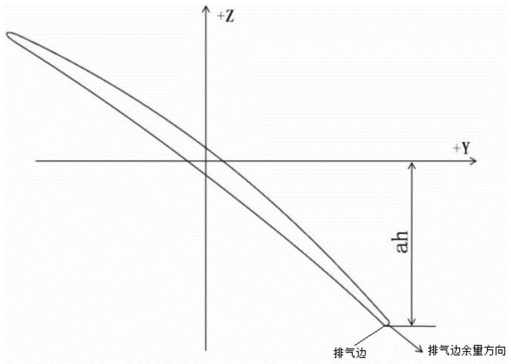
The forming process of the blisk blade mainly comprises two processes of numerical control milling and vibration finishing, although the applied model is a theoretical model in the numerical control milling process, the allowance of each part of the blisk after being processed is inconsistent relative to the theoretical profile due to the difference of curvature, rigidity, cutter contact point, cutter shaft angle and the like of each part of the blisk in the processing process, especially the shape of an exhaust edge and an ah value (as shown in figure 1, ah value in a blade coordinate system represents a Z coordinate value of a straight line which is parallel to a Y axis and tangent to an exhaust edge arc) are easy to be out of tolerance, and the removal amount of the exhaust edge is relatively larger than other parts of the blisk in the vibration finishing process, so that the final blisk section ah of the blisk is out of tolerance, and therefore a certain allowance needs to be reserved for the blisk section ah in the numerical control milling process to ensure that the final ah meets the requirement.
If the exhaust edge allowance is directly increased in the numerical control milling process of the integral blade disc blade, the exhaust edge allowance increasing direction is the normal direction of the exhaust edge section line, and the blade profile section ah is the axial direction, as shown in fig. 1, the effect of the exhaust edge allowance increasing on the increase of the blade profile section ah is not obvious, and if the exhaust edge allowance is excessively increased, the shape of the exhaust edge is easy to meet the requirement.
Disclosure of Invention
In order to solve the technical problems, the invention aims to provide a non-uniform margin modeling method based on blade section machining errors, wherein numerical control programming and machining verification are performed by axially offsetting exhaust edge contour points according to blade section ah machining errors and completing construction of an offset non-uniform margin model, so that the machining test period is greatly shortened, and the blade section ah value and the exhaust edge shape machining accuracy are improved.
The invention provides a non-uniform margin modeling method based on machining errors of a blade section of a blisk, which comprises the following steps of:
step 1: analyzing ah processing errors of all to-be-detected sections of the blisk blade profile to determine ah processing error values of all to-be-detected sections;
step 2: determining compensation coefficients and compensation values of all sections of the blade profile according to the material of the blisk part, the rigidity of a processing part and the change condition of a processing cutter shaft;
and step 3: introducing a design model of the integral blade disc blade, and determining the position and the shape of a blade profile exhaust edge;
and 4, step 4: extracting an exhaust edge contour line, and reading the coordinates (X, Y, Z) of the intersection point of the contour line and each blade profile section line, namely the coordinate values of the exhaust edge contour points of the blade profiles;
and 5: according to the compensation values of all the sections determined in the step 2, the Z-direction coordinate value of the profile point of the blade-type exhaust edge is biased along the-Z direction, the X, Y-direction coordinate value is unchanged, and the biased exhaust edge profile point coordinates (X, Y, Z') are generated;
step 6: constructing exhaust edge arcs respectively tangent to a straight line passing through the offset exhaust edge contour point and parallel to the Y axis, a blade basin contour line and a blade back contour line in a plane where the blade section line is located;
and 7: cutting and connecting the exhaust edge circular arc constructed in the step 6 with the tangent point of the leaf basin contour line and the tangent point of the leaf back contour line to form a leaf profile section line which is closed after compensation;
and 8: repeating the steps 6 and 7 to complete the compensation of the exhaust edges of the rest sections and the reconstruction of the sections;
and step 9: constructing a non-uniform allowance model of the blisk blade according to all reconstructed blade profile section lines;
step 10: performing numerical control milling programming based on the blisk blade non-uniform allowance model;
step 11: processing tests are carried out by applying the numerical control milling program output in the step 10, three-coordinate detection is carried out on the processed blade profile, and a blade profile section ah value and an exhaust edge shape detection report are output;
step 12: performing error analysis on the ah value of the processed blade section and the shape of the exhaust edge according to the detection report, and adjusting the compensation coefficient and the compensation value in the step (2);
step 13: and repeating the step 5-12 until the sectional ah value and the shape of the exhaust edge of the blade profile of the blisk meet the requirements of the process.
In the modeling method for the non-uniform allowance based on the machining error of the blade section of the blisk, the step 1 specifically comprises the following steps:
step 1.1: comparing the ah value of the cross section of the same position of each blade in the machined blisk with a theoretical ah value, and determining the ah error value of the cross section of the same position of each blade;
step 1.2: averaging the ah error values of the sections at the same positions of the blades to obtain the ah processing error value of the section to be detected of the blisk blade profile;
step 1.3: and repeating the step 1.2 to obtain ah error values of each section to be measured of the blisk.
In the modeling method for the non-uniform allowance based on the machining error of the blade section of the blisk, the compensation value is calculated in the step 2 according to the following formula:
the compensation value is the compensation coefficient K multiplied by ah processing error value, wherein the compensation coefficient K is 0.8-1.3.
In the modeling method for the non-uniform allowance based on the machining error of the blade section of the blisk, the step 5 is specifically as follows: and subtracting the corresponding compensation value from the Z coordinate value of the profile point of the exhaust edge of the blade profile to obtain the Z coordinate value after the offset, wherein the X, Y coordinate value is unchanged.
The non-uniform margin modeling method based on the blade section processing error at least has the following beneficial effects: the invention provides a non-uniform margin modeling method based on blade section processing errors for an ah value and an exhaust edge shape of a blisk blade section of an aircraft engine for the first time, which can greatly shorten the processing test period and improve the ah value and the exhaust edge shape processing accuracy. The technology can be applied to the numerical control milling process of various blisk blades, and has great economic effect and social benefit. The processing test shows that: according to the method, the non-uniform margin modeling is carried out on the exhaust edge of the blade of the blisk, the margin distribution of the exhaust edge area of the blade profile is optimized, the processing test period is greatly shortened, and the processing precision of the ah of the blade profile section is improved. The ah value of the blade section and the shape of the exhaust edge of the machined blade of the blisk meet the process requirements.
Drawings
FIG. 1 is a schematic view showing the ah value of the blade section, the position of the exhaust edge and the allowance direction of the exhaust edge;
FIG. 2 is a flow chart of a non-uniform margin modeling method based on blisk blade section machining errors in accordance with the present invention;
FIG. 3 is a schematic view of a profile point of a discharge edge of each section of a vane profile according to an embodiment of the present invention;
FIG. 4 illustrates a reconstruction of a blade profile section exhaust edge according to an embodiment of the present invention;
FIG. 5 is a cross-sectional view B of a compensated reconstructed blade profile according to an embodiment of the present inventionS1
FIG. 6 is a cross-sectional view of a fully reconstructed compensated airfoil according to an embodiment of the present invention;
FIG. 7 is a graph showing the results of measuring the shape of the processed exhaust edge according to the present invention.
Detailed Description
As shown in FIG. 2, the invention relates to a non-uniform margin modeling method based on machining errors of a blade section of a blisk, which comprises the following steps:
step 1: analyzing ah processing error of each section to be detected of the blisk blade profile, and determining ah processing error value of each section to be detected, wherein the step 1 specifically comprises the following steps:
step 1.1: comparing the ah value of the cross section of the same position of each blade in the machined blisk with a theoretical ah value, and determining the ah error value of the cross section of the same position of each blade;
step 1.2: averaging the ah error values of the sections at the same positions of the blades to obtain the ah processing error value of the section to be detected of the blisk blade profile;
step 1.3: and repeating the step 1.2 to obtain ah error values of each section to be measured of the blisk.
In this embodiment, each blade in the blisk selects 6 sections to be measured, S1-S6. The ah error values of each section to be measured of the blisk are obtained through the calculation in the step 1.2 as follows:
S1section ah error value: 0.076 mm;
S2section ah error value: 0.063 mm;
S3section ah error value: 0.054 mm;
S4section ah error value: 0.047 mm;
S5section ah error value: 0.041 mm;
S6section ah error value: 0.033 mm.
Step 2: determining compensation coefficients and compensation values of all sections of the blade profile according to the material of the blisk part, the rigidity of a processing part and the change condition of a processing cutter shaft;
in specific implementations, the compensation value is calculated according to the following formula:
the compensation value is the compensation coefficient K × ah processing error value. The supplement coefficient K is 0.8-1.3. S1Section compensation value is equal to compensation coefficient KxS1Error value of section ah is 1.15 × 0.076 is 0.0874S2Section compensation value is equal to compensation coefficient KxS2Error value of section ah is 1.12 × 0.063 is 0.07056S3Section compensation value is equal to compensation coefficient KxS3Error value of section ah is 1.09 × 0.054 is 0.05886S4Section compensation value is equal to compensation coefficient KxS4Error value of section ah is 1.03 × 0.047 is 0.04841S5Section compensation value is equal to compensation coefficient KxS5Error value of section ah is 0.98 × 0.041 0.04018S6Section compensation value is equal to compensation coefficient KxS6Error value of section ah is 0.87 × 0.033 is 0.02871
And step 3: introducing a design model of the integral blade disc blade, and determining the position and the shape of a blade profile exhaust edge;
and 4, step 4: and extracting the exhaust edge contour line, and reading the coordinates (X, Y, Z) of the intersection point of the contour line and each section line of the blade profile, namely the coordinate values of the exhaust edge contour points of the blade profile. As shown in FIG. 3, 6 intersections of the 6 airfoil sections with the exhaust side contour line are P1-P6The coordinate values of the profile points of the exhaust edge of the 6 blade profiles are as follows:
P1(X,Y,Z)=(270,8.9417,-7.7952)
P2(X,Y,Z)=(264,11.4062,-8.4869)
P3(X,Y,Z)=(258,11.5433,-8.9546)
P4(X,Y,Z)=(252,10.3578,-9.3041)
P5(X,Y,Z)=(246,9.6411,-9.9658)
P6(X,Y,Z)=(242,8.0946,-10.4446)
and 5: according to the compensation values of the sections determined in the step 2, biasing the Z-direction coordinate value of each blade-type exhaust edge contour point along the-Z direction, keeping the X, Y-direction coordinate value unchanged, and generating a biased exhaust edge contour point coordinate (X, Y, Z');
P1'(X,Y,Z)=(270,8.9417,-7.8826)
P2'(X,Y,Z)=(264,11.4062,-8.5575)
P3'(X,Y,Z)=(258,11.5433,-9.0135)
P4'(X,Y,Z)=(252,10.3578,-9.3525)
P5'(X,Y,Z)=(246,9.6411,-10.0060)
P6'(X,Y,Z)=(242,8.0946,-10.4733)
in specific implementation, the Z coordinate value of the profile point of the exhaust edge of the blade profile is subtracted by the corresponding compensation value to obtain the Z coordinate value after the offset, and the X, Y coordinate value is unchanged.
Step 6: constructing exhaust edge arcs respectively tangent to a straight line passing through the offset exhaust edge contour point and parallel to the Y axis, a blade basin contour line and a blade back contour line in a plane where the blade section line is located;
in specific implementation, as shown in FIG. 4, S is used1For example, a straight line L parallel to the Y axis and passing through the offset exhaust edge contour points (270, 8.9417, -7.8826) is constructed in the plane X-270 mmY1Exhaust edge arc D tangent to 3 lines of blade basin contour line and blade back contour lineTE1
And 7: the exhaust edge arc D constructed in the step 6 is roundedTE1Cutting and connecting with the tangent point of the contour line of the leaf basin and the tangent point of the contour line of the leaf back to form a leaf profile section line B which is closed after compensationS1As shown in fig. 5;
and 8: repeating the steps 6 and 7 to complete the exhaust edge compensation and the section reconstruction of the sections from S2 to S6; forming closed leaf section lines BS2, BS3, BS4, BS5 and BS6 after compensation, as shown in FIG. 6;
and step 9: constructing a blisk blade non-uniform margin model according to all reconstructed blade profile section lines, as shown in fig. 7;
step 10: performing numerical control milling programming based on the blisk blade non-uniform allowance model;
step 11: processing tests are carried out by applying the numerical control milling program output in the step 10, three-coordinate detection is carried out on the processed blade profile, and a blade profile section ah value and an exhaust edge shape detection report are output;
step 12: performing error analysis on the ah value of the processed blade section and the shape of the exhaust edge according to the detection report, and adjusting the compensation coefficient and the compensation value in the step (2);
step 13: and repeating the step 5-12 until the sectional ah value and the shape of the exhaust edge of the blade profile of the blisk meet the requirements of the process.
Through practical processing verification, according to the method, the non-uniform allowance modeling is carried out on the exhaust edge of the blade of the blisk, the profile point of the exhaust edge is axially offset according to the processing error, and the construction of the offset non-uniform allowance model is completed, so that numerical control programming and processing verification are carried out, the processing test period is greatly shortened, and the processing precision of the blade profile section ah is improved. The ah value of the blade section and the shape of the exhaust edge of the machined blade of the blisk meet the process requirements.
The invention provides a non-uniform margin modeling method for an aero-engine blisk based on blade section machining errors for the first time, successfully applies the related technology to the numerical control milling process of a certain model of blisk blade, greatly shortens the machining test period, and improves the machining precision of a blade section ah. To date, there is no non-uniform margin modeling method for aircraft engine blisk parts based on blade section machining errors. The technology can be applied to the numerical control milling process of various blisk blades, has strong universality and practicability, and has great economic effect and social benefit.
The above description is only for the purpose of illustrating the preferred embodiments of the present invention and is not to be construed as limiting the scope of the present invention, which is defined by the appended claims.

Claims (4)

1.一种基于整体叶盘叶片截面加工误差的非均匀余量建模方法,其特征在于,包括:1. a non-uniform margin modeling method based on integral blisk blade section machining error, is characterized in that, comprises: 步骤1:对整体叶盘叶型各待测截面的ah加工误差进行分析,确定各待测截面的ah加工误差值;Step 1: Analyze the ah machining error of each section to be measured for the overall blisk blade shape, and determine the ah machining error value of each section to be measured; 步骤2:根据整体叶盘零件材料、加工部位刚性及加工刀轴变化情况确定叶型各截面的补偿系数及补偿值;Step 2: Determine the compensation coefficient and compensation value of each section of the airfoil according to the material of the overall blisk part, the rigidity of the machining part and the change of the machining tool axis; 步骤3:导入整体叶盘叶片设计模型,确定叶型排气边部位及形状;Step 3: Import the overall blisk blade design model, and determine the position and shape of the airfoil exhaust edge; 步骤4:抽取排气边轮廓线,并读取该轮廓线与各个叶型截面线的交点坐标(X,Y,Z),即为叶型排气边轮廓点坐标值;Step 4: Extract the contour line of the exhaust edge, and read the coordinates (X, Y, Z) of the intersection point between the contour line and each airfoil section line, which is the coordinate value of the contour point of the airfoil exhaust edge; 步骤5:根据步骤2确定的各截面的补偿值对叶型排气边轮廓点的Z向坐标值沿-Z向进行偏置,X、Y向坐标值不变,生成偏置后的排气边轮廓点坐标(X,Y,Z′);Step 5: According to the compensation value of each section determined in step 2, the Z coordinate value of the airfoil exhaust edge contour point is offset along the -Z direction, and the X and Y coordinate values remain unchanged to generate the offset exhaust. Edge contour point coordinates (X, Y, Z'); 步骤6:在叶型截面线所在平面内构建分别与通过偏置后的排气边轮廓点且平行于Y轴的直线、叶盆轮廓线、叶背轮廓线相切的排气边圆弧;Step 6: Construct exhaust edge arcs that are tangent to the straight line, the blade basin contour line and the blade back contour line that pass through the offset exhaust edge contour point and are parallel to the Y axis in the plane of the airfoil section line; 步骤7:将步骤6构建的排气边圆弧与叶盆轮廓线的切点、叶背轮廓线的切点处进行裁剪与连接,形成补偿后闭合的叶型截面线;Step 7: Cut and connect the tangent point of the exhaust edge arc constructed in step 6 with the contour line of the blade basin and the tangent point of the contour line of the blade back to form a closed blade section line after compensation; 步骤8:重复步骤6和7,完成其余截面排气边补偿与截面重构;Step 8: Repeat steps 6 and 7 to complete the exhaust edge compensation and section reconstruction of the remaining sections; 步骤9:根据所有重构的叶型截面线构建整体叶盘叶片非均匀余量模型;Step 9: Construct the non-uniform margin model of the overall blisk blade according to all the reconstructed airfoil section lines; 步骤10:基于整体叶盘叶片非均匀余量模型进行数控铣削程序编制;Step 10: Compile the NC milling program based on the non-uniform margin model of the blisk blade; 步骤11:应用步骤10输出的数控铣削程序编制进行加工试验,并对加工后的叶片型面进行三坐标检测,输出叶型截面ah值和排气边形状检测报告;Step 11: Use the CNC milling program output in step 10 to perform a processing test, and perform three-coordinate detection on the processed blade profile, and output the ah value of the blade profile section and the exhaust edge shape detection report; 步骤12:根据检测报告对加工后的叶型截面ah值和排气边形状进行误差分析,并调整步骤2的补偿系数及补偿值;Step 12: Carry out error analysis on the ah value of the processed airfoil section and the shape of the exhaust edge according to the test report, and adjust the compensation coefficient and compensation value in Step 2; 步骤13:重复步骤5-12至加工后整体叶盘叶型截面ah值和排气边形状满足工序要求。Step 13: Repeat steps 5-12 until the ah value of the blade profile section and the shape of the exhaust edge of the overall blisk after processing meet the process requirements. 2.如权利要求1所述的基于整体叶盘叶片截面加工误差的非均匀余量建模方法,其特征在于,所述步骤1具体为:2. The non-uniform margin modeling method based on the machining error of the overall blisk blade section as claimed in claim 1, wherein the step 1 is specifically: 步骤1.1:将加工后的整体叶盘中各叶片相同位置截面的ah值与理论ah值进行对比,确定各叶片相同位置截面的ah误差值;Step 1.1: Compare the ah value of the section at the same position of each blade in the processed blisk with the theoretical ah value to determine the ah error value of the section at the same position of each blade; 步骤1.2:将各叶片相同位置截面的ah误差值求平均值,获得整体叶盘叶型该待测截面的ah加工误差值;Step 1.2: Calculate the average value of the ah error value of the section at the same position of each blade to obtain the ah processing error value of the section to be measured for the overall blisk blade shape; 步骤1.3:重复步骤1.2获得整体叶盘各个待测截面的ah误差值。Step 1.3: Repeat step 1.2 to obtain the ah error value of each section of the blisk to be measured. 3.如权利要求1所述的基于整体叶盘叶片截面加工误差的非均匀余量建模方法,其特征在于,所述步骤2中根据下式计算补偿值:3. The non-uniform margin modeling method based on the machining error of the overall blisk blade section as claimed in claim 1, wherein in the step 2, the compensation value is calculated according to the following formula: 补偿值=补偿系数K×ah加工误差值,其中补充系数K=0.8~1.3。Compensation value=compensation coefficient K×ah machining error value, wherein the supplementary coefficient K=0.8~1.3. 4.如权利要求1所述的基于整体叶盘叶片截面加工误差的非均匀余量建模方法,其特征在于,所述步骤5具体为:4. The non-uniform margin modeling method based on the machining error of the overall blisk blade section as claimed in claim 1, wherein the step 5 is specifically: 将叶型排气边轮廓点的Z向坐标值减去相应的补偿值,获得偏置后的Z向坐标值,X、Y向坐标值不变。Subtract the corresponding compensation value from the Z coordinate value of the airfoil exhaust edge contour point to obtain the offset Z coordinate value, and the X and Y coordinate values remain unchanged.
CN202111217767.6A 2021-10-19 2021-10-19 A Non-uniform Allowance Modeling Method Based on Blade Section Machining Error Active CN114002995B (en)

Priority Applications (1)

Application Number Priority Date Filing Date Title
CN202111217767.6A CN114002995B (en) 2021-10-19 2021-10-19 A Non-uniform Allowance Modeling Method Based on Blade Section Machining Error

Applications Claiming Priority (1)

Application Number Priority Date Filing Date Title
CN202111217767.6A CN114002995B (en) 2021-10-19 2021-10-19 A Non-uniform Allowance Modeling Method Based on Blade Section Machining Error

Publications (2)

Publication Number Publication Date
CN114002995A true CN114002995A (en) 2022-02-01
CN114002995B CN114002995B (en) 2023-07-28

Family

ID=79923224

Family Applications (1)

Application Number Title Priority Date Filing Date
CN202111217767.6A Active CN114002995B (en) 2021-10-19 2021-10-19 A Non-uniform Allowance Modeling Method Based on Blade Section Machining Error

Country Status (1)

Country Link
CN (1) CN114002995B (en)

Cited By (1)

* Cited by examiner, † Cited by third party
Publication number Priority date Publication date Assignee Title
CN118795838A (en) * 2024-09-14 2024-10-18 中国航发北京航空材料研究院 A method and system for adjusting grinding allowance of turbine guide blades

Citations (4)

* Cited by examiner, † Cited by third party
Publication number Priority date Publication date Assignee Title
EP2596895A1 (en) * 2011-11-28 2013-05-29 Fanuc Corporation Wire electric discharge machining method and wire electric discharge machine for machining tool that uses ultra-hard material and is mounted to rotating shaft
FR3009104A1 (en) * 2013-07-29 2015-01-30 Snecma METHOD FOR MODELING A BLADE OF A NON-CARBENE PROPELLER
CN107577874A (en) * 2017-09-06 2018-01-12 厦门大学 A Method for Determining Design Shrinkage Rate of Precision Casting Mold for Hollow Turbine Blades
CN109800442A (en) * 2017-11-16 2019-05-24 中国航发商用航空发动机有限责任公司 Reconstruction method of blade model of aircraft engine

Patent Citations (4)

* Cited by examiner, † Cited by third party
Publication number Priority date Publication date Assignee Title
EP2596895A1 (en) * 2011-11-28 2013-05-29 Fanuc Corporation Wire electric discharge machining method and wire electric discharge machine for machining tool that uses ultra-hard material and is mounted to rotating shaft
FR3009104A1 (en) * 2013-07-29 2015-01-30 Snecma METHOD FOR MODELING A BLADE OF A NON-CARBENE PROPELLER
CN107577874A (en) * 2017-09-06 2018-01-12 厦门大学 A Method for Determining Design Shrinkage Rate of Precision Casting Mold for Hollow Turbine Blades
CN109800442A (en) * 2017-11-16 2019-05-24 中国航发商用航空发动机有限责任公司 Reconstruction method of blade model of aircraft engine

Non-Patent Citations (2)

* Cited by examiner, † Cited by third party
Title
DONGBO WU: "《Machining fixture for adaptive CNC machining process of near-net-shaped jet engine blade》", 《CHINESE JOURNAL OF AERONAUTICS》, pages 1311 *
李丙才: "《烟气轮机动叶片的参数化建模及加工仿真》", 《 工具技术》, no. 2, pages 78 *

Cited By (2)

* Cited by examiner, † Cited by third party
Publication number Priority date Publication date Assignee Title
CN118795838A (en) * 2024-09-14 2024-10-18 中国航发北京航空材料研究院 A method and system for adjusting grinding allowance of turbine guide blades
CN118795838B (en) * 2024-09-14 2024-11-15 中国航发北京航空材料研究院 A method and system for adjusting grinding allowance of turbine guide blades

Also Published As

Publication number Publication date
CN114002995B (en) 2023-07-28

Similar Documents

Publication Publication Date Title
CN113814673A (en) Geometric self-adaptive machining method for titanium alloy blisk welding part of large fan
JP5087794B2 (en) How to repair a workpiece such as a turbomachine blade of a dam blade
CN105242637A (en) Aviation thin-wall blade compensation processing method
CN101653921A (en) Error compensation method of numerical control grinding contour of camshaft
Hou et al. Geometric modelling of thin-walled blade based on compensation method of machining error and design intent
CN102622489B (en) Five-axis side milling cutting force predicting method based on ACIS platform
CN102222149B (en) Error compensation method for integral turbine blade machining based on mathematical model reconstruction
CN109214032B (en) An adaptive machining method for hollow blades
CN108544181B (en) A method for repairing damaged leaves of an integral leaf disk
CN105739440A (en) Adaptive machining method of wide-chord hollow fan blade
CN108445835B (en) A Method for Part Machining Dimension Prediction of CNC Machine Tool
CN104794305B (en) Instantaneous Milling force prediction method during variable curvature curved surface side milling
CN104289748A (en) Large-scale thin-wall skin self-adapting equal wall-thickness milling system and processing method thereof
CN108803487A (en) A kind of point profile errors prediction technique on part side milling surface
CN109663997B (en) Processing method for electrolytic primary forming of part with complex profile
CN112989517A (en) Trajectory solving method for grinding rear cutter face of ball head by adopting parallel grinding wheel
RU2607867C2 (en) Adaptive treatment of cast blades
CN117709024A (en) Compensation method for angle deviation of working face of aviation precision forging blade
Zhao et al. Measured data-driven shape-adaptive machining via spatial deformation of tool cutter positions
CN109571137A (en) A kind of compensation method improving thin-walled parts machining accuracy
CN114002995A (en) Non-uniform allowance modeling method based on blade section machining error
Prabha et al. Machining of steam turbine blade on 5-axis CNC machine
CN114310484A (en) Large-scale shell thin-wall characteristic online measurement compensation method
Huang et al. Allowance extraction considering of inner and outer contour and experimental research on belt grinding of hollow blade
CN109299581A (en) A Method for Predicting Milling Force of End Milling Cutter Combined with Surface Interpolation

Legal Events

Date Code Title Description
PB01 Publication
PB01 Publication
SE01 Entry into force of request for substantive examination
GR01 Patent grant
GR01 Patent grant