Disclosure of Invention
The invention aims to solve the technical problem of providing a particle compact fuel element which can avoid the sintering reconstruction phenomenon in the middle area of the fuel element and has simpler processing, manufacturing and heat transfer control.
The technical scheme adopted by the invention for solving the technical problems is as follows: providing a particulate dense fuel element comprising an inner cladding and an outer cladding disposed internally and externally, a closed annular cavity formed between the inner cladding and the outer cladding; the closed interior cavity of the inner cladding forms an intermediate region of the particulate dense fuel element;
the annular cavity is filled with a particulate composition comprising fuel particles.
Preferably, the fuel particles are particulate fuel matter containing at least one of thorium, uranium, plutonium.
Preferably, the fuel particles are uranium dioxide particle fuel.
Preferably, the fuel particles are TRISO-coated particles.
Preferably, the particulate composition further comprises functional particles;
the functional particles include one or more of transmutation particles, burnable poison particles, moderating particles, thermal conductivity enhancing particles, parent particles for production of radionuclides for nuclear technology.
Preferably, said transmutation particles are particles containing minor actinides or long-life fission product species resulting from post-processing of spent fuel; wherein the minor actinides comprise Np, Pu, Am, Cm, and the long-lived fission products comprise90Sr、137Cs、135Cs、99Tc、129I。
Preferably, said transmutation particles also contain U and/or Pu.
Preferably, the burnable poison particles comprise one or more of gadolinium oxide, dysprosium oxide, erbium oxide, boron carbide, zirconium boride and borosilicate glass.
Preferably, the moderating particles comprise one or more of beryllium, beryllium oxide, graphite, graphene, zirconium hydride, yttrium hydride, lithium hydride, niobium hydride, tantalum hydride, vanadium hydride, calcium hydride, titanium hydride, scandium hydride, thorium hydride, and cerium hydride.
Preferably, the thermal conductivity of the thermal conductivity enhancement particles is more than or equal to 10W/(m.K).
Preferably, the parent particle for producing a radionuclide for nuclear technology comprises12C、67Zn、46Ca、47Ca、47Ti、89Y、59Co、104Ru、108Pd、112Sn、130Te、176Lu、164Dy and191one or more of Ir.
Preferably, a thermal conductivity enhanced gas filled in the particle gaps of the particle composition is further provided in the annular cavity.
Preferably, the thermally enhanced gas is helium.
Preferably, the volume of said annular cavity is between 40% and 90% of the total volume of said particulate dense fuel elements.
Preferably, the wall thickness of the inner cladding is 0.3 mm-10 mm; the wall thickness of the outer casing is 0.3 mm-10 mm.
Preferably, the wall surface of the inner cladding is distributed with micropores and/or microcracks.
Preferably, at least one baffle is arranged between the inner cladding and the outer cladding, and the baffle divides the annular cavity into at least two chambers; each of the chambers is filled with the particulate composition.
Preferably, the cross-sectional shape of the inner cladding is circular, elliptical, polygonal or irregular;
the cross section of the outer casing is circular, elliptical, polygonal or irregular.
Preferably, the inner cladding is made of an inorganic non-metallic material or a metallic material.
Preferably, the inorganic non-metallic material comprises one or more of MAX phase ceramic, silicon carbide fiber woven silicon carbide ceramic composite, zirconium carbide, high entropy carbide, graphite, carbon-carbon composite, alumina, zirconia, beryllia;
the metallic material comprises one or more of zirconium alloy, stainless steel, refractory metals, and alloys thereof.
Preferably, the outer envelope is made of an inorganic non-metallic material or a metallic material.
Preferably, the inorganic non-metallic material comprises one or more of MAX phase ceramic, silicon carbide fiber woven silicon carbide ceramic composite, zirconium carbide, high entropy carbide, graphite, carbon-carbon composite, alumina, zirconia, beryllia;
the metallic material comprises one or more of zirconium alloy, stainless steel, refractory metals, and alloys thereof.
Compared with a single-shell particle dense fuel element, the particle dense fuel element provided by the invention has the advantages that the particles are loaded in the annular cavity between the inner shell and the outer shell, so that the sintering reconstruction phenomenon of the middle area of the particle dense fuel element is avoided, the design of the fuel element is more stable, and the performance of the fuel element has better predictability; the inner cavity of the inner cladding shell is hermetically arranged, so that the inner cladding shell is not contacted with the coolant, the processing, manufacturing and positioning of the fuel are more convenient, the heat transfer design is simpler, and the difficulty in controlling the heat conduction quantity of the inner cladding shell and the outer cladding shell when the inner cladding shell and the outer cladding shell are contacted with the coolant is solved; the closed middle area provided by the inner cavity of the inner enclosure provides additional space for expansion, swelling and fission gas release of the particle composition containing the fuel particles under accident or transient conditions, and improves the safety of the fuel element.
The granular dense fuel element of the invention is suitable for various reactor types such as high-temperature gas cooled reactor, light water reactor, molten salt reactor, lead-cooled reactor, sodium-cooled reactor and the like.
Detailed Description
For a more clear understanding of the technical features, objects and effects of the present invention, embodiments of the present invention will now be described in detail with reference to the accompanying drawings.
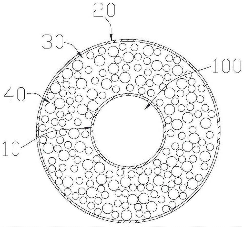
Referring to fig. 1, the particulate densified fuel element of the present invention includes an inner cladding 10 and an outer cladding 20 disposed internally and externally, a closed annular cavity 30 formed between the inner cladding 10 and the outer cladding 20; the annular cavity 30 is filled with a particulate composition 40.
The inner cladding 10 and the outer cladding 20 are both tubular structures, the outer cladding 20 is sleeved outside the inner cladding 10 to form a double cladding structure, and two ends of the double cladding structure are sealed (for example, in a form of being sealed by end plugs and the like), so that the annular cavity 30 and the inner cavity 100 of the inner cladding 10 form a sealed cavity; the annular cavity 30 is isolated (not communicated) with the inner cavity 100 of the inner package shell 10; the inner cavity 100 of the inner cladding 10 also serves as the intermediate region for the particulate densified fuel element.
The volume of the annular cavity is 40% to 90% of the total volume of the particulate compacted fuel element, such that the particulate composition 40 filled in the annular cavity 30 has a certain volume. The vibratory compaction may be performed simultaneously with or after the particulate composition 40 is loaded into the annular cavity 30.
Within the annular cavity 30, the particulate composition 40 includes fuel particles. The fuel particles may be particulate fuel material containing at least one of thorium, uranium, plutonium. For example, the fuel particles comprise UO2、PuO2、PuN、MOX、ThN、ThO2、UN、UC、UB2、U3Si2One or more of U-Mo alloy, U-Zr alloy, U-Pu-Zr alloy and TRISO coated particles. Preferably, the fuel particles are selected from the group of triply isotropically coated particle fuels developed in high temperature gas cooled reactors, i.e. TRISO coated particles. The TRISO-coated particles can be used as the particle fuel which is mature in technology and industrially produced, and can realize large-scale industrial mass production, so that the manufacturing cost of the TRISO particles is further reduced by co-spreading the cost after scale-up.
The particulate composition 40 may also include functional particles. The functional particles comprise one or more of transmutation particles, burnable poison particles, moderation particles, thermal conductivity enhancement particles and parent particles for producing radionuclide for nuclear technology; the multifunctional fuel element can be realized through the combination of different functional particles, so that the particle dense fuel element can meet the requirements of multi-scene applications such as power generation, transmutation treatment of nuclear waste, radioactive isotope production, comprehensive utilization of uranium-thorium resources and the like, and has multi-kinetic energy. Wherein:
the addition of transmutation particles in the particulate composition 40 enables the use of the particulate dense fuel elements for transmutation processing of high level waste. Transmutation particles are particles containing minor actinides (transuranics) or long-life fission product species resulting from post-processing of spent fuel; minor actinides including Np, Pu, Am, Cm, long-lived fission products including90Sr、137Cs、135Cs、99Tc、129I. The transmutation particles may also contain fuel species such as U and/or Pu. For example, the transmutation particles can be oxide particles containing elements such as Np, Pu, Am, Cm, and the like.
The burnable poison particles are used to improve the neutronics balance of the particle composition 40 during service operation. The burnable poison particles may include one or more of gadolinium oxide, dysprosium oxide, erbium oxide, boron carbide, zirconium boride and borosilicate glass.
The moderating particles serve to improve the neutron economy of the particle composition 40. The moderating particles may include one or more of beryllium, beryllium oxide, graphite, graphene, zirconium hydride, yttrium hydride, lithium hydride, niobium hydride, tantalum hydride, vanadium hydride, calcium hydride, titanium hydride, scandium hydride, thorium hydride, and cerium hydride.
The thermal conductivity enhancing particles are used for improving the heat transfer performance of the particle composition 40, and are made of a material with a thermal conductivity of more than or equal to 10W/(m.K), for example, silicon carbide, graphene or beryllium oxide, so that the thermal conductivity of the thermal conductivity enhancing particles is more than or equal to 10W/(m.K).
The parent particles of the radioactive nuclide for nuclear production technology are particles capable of forming the radioactive nuclide under reactor irradiation, and the formed radioactive nuclide can be used for industrial radioactive sources, nuclear batteries, medical radiopharmaceuticals and the like. The parent particle is selected from12C、67Zn、46Ca、47Ca、47Ti、89Y、59Co、104Ru、108Pd、112Sn、130Te、176Lu、164Dy and191one or more of Ir. For example,59radioactive nuclide for industrial radioactive source can be prepared by Co after reactor irradiation60Co,60Co can be applied to radiation breeding, nondestructive inspection, irradiation processing or irradiation sterilization and other scenes.
In the granular composition 40, the different number of different types of granules can meet the radioactivity requirements of different scenes, the granular shape avoids the cutting requirement in the processing and assembling operation after irradiation, the radioactive pollution can be reduced, and the dangerous radioactive operation requirement can be reduced.
In the particulate composition 40, each particle (fuel particle, functional particle) may be an ellipsoidal particle, a spherical particle, a short fiber-like particle, or an irregularly shaped particle, or include one or more of the above shapes, respectively. Preferably, the particles in the particle composition 40 are spherical particles having a particle size of 80 μm to 800 μm. For ellipsoidal particles, the major axis can include at least one size range of 30 μm to 120 μm and 300 μm to 900 μm. For short fiber-like particles, the length of the long axis of the fibers therein may be, but is not limited to, 30 μm to 120 μm.
Among the functional particles of the particle composition 40, the fuel particles, transmutation particles are preferably ellipsoidal particles or spherical particles; the matrix particles are preferably short fiber-like particles.
In terms of size, the particles in the particle composition 40 may be uniform in one size or may include a plurality of different sizes. Preferably, the particles in the particulate composition 40 include at least two sizes, such that smaller sized particles can fill the voids formed by the stacking of larger sized particles, increasing the bulk density of the particles; examples include, but are not limited to, 10 μm to 120 μm, 200 μm to 490 μm, and 500 μm to 1200 μm.
In addition, the annular cavity 30 can be filled with heat conduction enhanced gas, and the heat conduction enhanced gas is filled in the particle gaps of the particle composition 40 to improve the heat transfer performance; the pressure of the filled heat conduction enhanced gas is less than 3 MPa. The thermally enhanced gas is preferably helium.
For the inner cladding 10, it is made of an inorganic non-metallic material or a metallic material. Wherein the inorganic non-metallic material comprises MAX phase ceramics (Ti)3SiC2、Ti2AlC, etc.), silicon carbide fiber braided silicon carbide ceramicCeramic composite materials (e.g. SiC)f/SiC), zirconium carbide, high entropy carbides, graphite, carbon-carbon composites (e.g., C/C), alumina, zirconia, beryllia. The metallic material comprises one or more of zirconium alloys, stainless steel, refractory metals and alloys thereof, including high entropy refractory alloys.
In the present invention, the wall thickness of the inner pack case 10 is 0.3mm to 10 mm; the wall thickness of the outer envelope 20 is 0.3mm to 10 mm. In a preferred embodiment, the wall thickness of the inner envelope 10 and the outer envelope 20 is greater than the wall thickness of a conventional zirconium alloy cladding.
For the outer envelope 20, it is made of an inorganic non-metallic material or a metallic material. Wherein the inorganic non-metallic material comprises MAX phase ceramics (Ti)3SiC2、Ti2AlC, etc.), silicon carbide fiber woven silicon carbide ceramic composite material (e.g., SiC)fOne or more of/SiC), zirconium carbide, high entropy carbides, graphite, carbon-carbon composites (e.g., C/C), alumina, zirconia, beryllia; the silicon carbide comprises a silicon carbide ceramic composite material (e.g. SiC) woven with silicon carbide fibersf/SiC). The metallic material comprises one or more of zirconium alloys, stainless steel, refractory metals and alloys thereof, including high entropy refractory alloys.
The outer envelope 20 and the inner envelope 10 may be made of the same material or may be made of different materials.
When both the outer and inner cladding shells 20, 10 are made of zirconium alloy, the particulate composition 40 containing the fuel particles applies a greater strain to the inner cladding 10 than the outer cladding shell 20 due to the greater service temperature of the inner cladding shell 10 than the outer cladding shell 20, reducing the risk of failure of the outer cladding shell 20 in contact with the coolant due to interaction with the fuel.
When the outer envelope 20 is made of zirconium alloy, the inner envelope 10 may also preferably be a silicon carbide ceramic composite material (SiC) woven with silicon carbide fibers having more excellent mechanical properties and better high temperature resistancef/SiC).
In terms of shape, the cross-sectional shape of the inner pack case 10 may be circular, elliptical, polygonal, irregular, or the like; the cross-sectional shape of the outer envelope 20 is circular, elliptical, polygonal, irregular, or the like.
In the first embodiment of the present invention, as shown in fig. 1, the inner pack case 10 and the outer pack case 20 are each a cylindrical tube structure, and both have a circular cross-sectional shape. The diameter of the inner envelope 10 may be 2.0mm to 5.0mm and the diameter of the outer envelope 20 may be 7.0mm to 15.5 mm.
In the second embodiment of the present invention, as shown in fig. 2, the cross-sectional shape of the inner pack case 10 is a circle or an ellipse, and the cross-sectional shape of the outer pack case 20 is a polygon formed of straight sides and arc sides.
In a third embodiment of the present invention, as shown in fig. 3, the cross-sectional shapes of the inner cladding 10 and the outer cladding 20 are both irregular shapes.
In a fourth embodiment of the present invention, as shown in fig. 4, the outer cladding 20 is a tubular structure with a constant diameter, and the inner cladding 10 is a tubular structure with a non-constant diameter, so that the inner cladding 10 has a plurality of different inner diameters in the axial length (height direction), and thus the annular cavity 30 also has a plurality of different widths in the height direction, and the particle composition loading amounts at different width positions are different, thereby realizing a core design with better performance and flattening the axial power distribution of the core. The arrangement of the inner cladding 10 and the annular cavity 20 of the embodiment enables the adjustment of the axial power distribution of the reactor core to be realized by fuel particles with the same enrichment degree but with different axial loading amounts, thereby avoiding the need of uranium enrichment which is expensive.
The shape of the non-constant diameter inner envelope 10 in longitudinal cross section may also be wavy.
In a fifth embodiment of the invention, as shown in fig. 5, at least one baffle 50 is provided between the inner cladding 10 and the outer cladding 20, the baffle 50 dividing the annular cavity 30 into at least two chambers 31; at least two chambers 31 are distributed along the circumference of the annular chamber 30. Each chamber 31 is filled with a particulate composition. The arrangement of the separated chambers 31 enables the leaked radioactive gas to be only the radioactive substance in the single chamber 31 when the fuel element is accidentally damaged, so that the total amount of the leaked radioactive substance is reduced, and the safety of the fuel element is improved.
In a sixth embodiment of the present invention, referring to fig. 6, on the basis of the first to fifth embodiments, micro holes and/or micro cracks 11 may be further distributed on the wall surface of the inner envelope 10. The micro-holes or micro-cracks 11 may be formed only on the inner wall surface or the outer wall surface of the inner envelope 10, or may penetrate through the opposite wall surfaces of the inner envelope 10. The pore size of the micropores and the width and length of the microcracks 11 are smaller than the size of each particle in the particle composition 40, preventing the passage of the particles. The micro-pores and micro-cracks 11 may be formed by machining or by a selected material of the inner cladding 10, such as a silicon carbide ceramic composite woven with silicon carbide fibers.
With reference to fig. 1 and 6, the micro-holes and/or micro-cracks 11 are disposed in the inner cladding 10 to form a weak area, and are damaged to a certain extent under an accident condition, so as to communicate the annular cavity 30 with the inner cavity 100 of the inner cladding 10, so that radioactive gas released under the accident enters the inner cavity 100 of the inner cladding 10, and more containing spaces are provided for releasing fission gas under the accident condition, and the inner cavity of the inner cladding 10 is equivalent to a pressure relief cabin, thereby reducing gas pressure in the fuel element and improving safety of the fuel element.
Referring to fig. 1 to 6, after the granular compact fuel element of the present invention is applied to a core, during operation, a coolant flows through the outer surface of the outer cladding 20 to remove heat generated by a nuclear reaction in the fuel element, and the inner cladding 10 is not in contact with the coolant.
The above description is only an embodiment of the present invention, and not intended to limit the scope of the present invention, and all modifications of equivalent structures and equivalent processes performed by the present specification and drawings, or directly or indirectly applied to other related technical fields, are included in the scope of the present invention.