CN114091237A - Method for identifying key sensitive equipment of digital reactor protection system - Google Patents
Method for identifying key sensitive equipment of digital reactor protection system Download PDFInfo
- Publication number
- CN114091237A CN114091237A CN202111222715.8A CN202111222715A CN114091237A CN 114091237 A CN114091237 A CN 114091237A CN 202111222715 A CN202111222715 A CN 202111222715A CN 114091237 A CN114091237 A CN 114091237A
- Authority
- CN
- China
- Prior art keywords
- protection system
- reactor protection
- fault tree
- spv
- equipment
- Prior art date
- Legal status (The legal status is an assumption and is not a legal conclusion. Google has not performed a legal analysis and makes no representation as to the accuracy of the status listed.)
- Granted
Links
Images


Classifications
-
- G—PHYSICS
- G06—COMPUTING OR CALCULATING; COUNTING
- G06F—ELECTRIC DIGITAL DATA PROCESSING
- G06F30/00—Computer-aided design [CAD]
- G06F30/20—Design optimisation, verification or simulation
-
- G—PHYSICS
- G21—NUCLEAR PHYSICS; NUCLEAR ENGINEERING
- G21D—NUCLEAR POWER PLANT
- G21D3/00—Control of nuclear power plant
- G21D3/001—Computer implemented control
-
- G—PHYSICS
- G06—COMPUTING OR CALCULATING; COUNTING
- G06F—ELECTRIC DIGITAL DATA PROCESSING
- G06F2119/00—Details relating to the type or aim of the analysis or the optimisation
- G06F2119/02—Reliability analysis or reliability optimisation; Failure analysis, e.g. worst case scenario performance, failure mode and effects analysis [FMEA]
-
- Y—GENERAL TAGGING OF NEW TECHNOLOGICAL DEVELOPMENTS; GENERAL TAGGING OF CROSS-SECTIONAL TECHNOLOGIES SPANNING OVER SEVERAL SECTIONS OF THE IPC; TECHNICAL SUBJECTS COVERED BY FORMER USPC CROSS-REFERENCE ART COLLECTIONS [XRACs] AND DIGESTS
- Y02—TECHNOLOGIES OR APPLICATIONS FOR MITIGATION OR ADAPTATION AGAINST CLIMATE CHANGE
- Y02E—REDUCTION OF GREENHOUSE GAS [GHG] EMISSIONS, RELATED TO ENERGY GENERATION, TRANSMISSION OR DISTRIBUTION
- Y02E30/00—Energy generation of nuclear origin
Landscapes
- Engineering & Computer Science (AREA)
- Physics & Mathematics (AREA)
- General Engineering & Computer Science (AREA)
- Theoretical Computer Science (AREA)
- Plasma & Fusion (AREA)
- High Energy & Nuclear Physics (AREA)
- Computer Hardware Design (AREA)
- Evolutionary Computation (AREA)
- Geometry (AREA)
- General Physics & Mathematics (AREA)
- Testing And Monitoring For Control Systems (AREA)
Abstract
The invention belongs to the field of nuclear power, and particularly relates to a method for identifying key sensitive equipment of a digital reactor protection system of a nuclear power plant. The digital reactor protection system has strong relevance among all the clamping pieces and complex logic, and the influence of the clamping piece fault on the whole system is difficult to be comprehensively analyzed by an FMEA (failure mode analysis) method. The method is complementary to the traditional SPV identification method, and provides a rapid and reliable temporary SPV equipment identification method for the digital reactor protection system for the nuclear power plant. The method mainly comprises the steps of establishing a fault tree model of a zero-dimension zero-repair test reactor protection system, wherein the obtained first-order cut set related equipment is SPV equipment; establishing boundary conditions of corresponding tests according to regular test procedures of a reactor protection system; and establishing a temporary boundary condition, and comparing the temporary boundary condition with a first-order cut set obtained by a fault tree model of the zero-dimensional zero-repairing test, wherein the equipment corresponding to the newly added first-order cut set is the temporary SPV of the system in the current state.
Description
Technical Field
The invention belongs to the field of nuclear power, and particularly relates to a method for identifying key sensitive equipment of a digital reactor protection system.
Background
With the advancement of the reform of the domestic power market system, higher requirements are put forward on the competitiveness of the nuclear power plant in the power market. Therefore, the reliability level of the system equipment of the nuclear power plant is improved, and the condition that the unplanned shutdown and shutdown of the unit become important contents of each power plant is reduced. An important content as a device reliability management system is device classification, and SPV (critical sensitive) devices are the most important in device classification management, and the method for identifying SPV devices mainly adopts FMEA (failure mode and impact analysis) and operation experience at present. However, with the widely adopted digital reactor protection system of newly built nuclear power plants in China, because the digital reactor protection system has strong relevance among all clamping pieces and relatively complex logic, the influence of the clamping piece fault on the whole system is difficult to be comprehensively analyzed by an FMEA (failure mode analysis) method, so that the invention establishes the logical relationship between the clamping piece fault mode and the misoperation of the reactor protection system by a fault tree method, and solves the defects of the FMEA analysis method.
Disclosure of Invention
1. The purpose is as follows:
the method provides a new method for identifying the SPV (key sensitive equipment) of the digital reactor protection system of the nuclear power plant, and is complementary with the traditional SPV identification method; the method for identifying the temporary SPV equipment of the digital reactor protection system is rapid and reliable and is provided for a nuclear power plant.
2. The technical scheme is as follows:
a method for identifying key sensitive equipment of a digital reactor protection system specifically comprises the following steps: the method comprises the following steps: determining a fault tree analysis boundary of the digital reactor protection system; step two: establishing a fault tree model taking control rod power loss caused by tripping of a shutdown breaker as a top event; step three: establishing boundary conditions of a fault tree corresponding to a periodic test of a reactor protection system; step four: step two and step three establish the real-time fault tree model of the digital reactor protection system together; step five: calculating the equipment corresponding to the first-order cut set basic event obtained by the fault tree model in the step two, and determining SPV equipment; step six: establishing a boundary condition for temporary SPV calculation of a digital reactor protection system; step seven: and step five and step six jointly calculate to obtain the temporary SPV equipment under the current system configuration.
The first step is as follows: determining a fault tree analysis boundary of a digital reactor protection system malfunction, which specifically comprises the following steps: the outer boundary of the typical digital reactor protection system comprises a shutdown circuit breaker serving as an actuating mechanism, a digital reactor protection system computer, a signal processing cabinet and an on-site transmitter; the inner boundary is a functional clamping piece in each cabinet.
The second step is that: establishing a fault tree model taking control rod power loss caused by tripping of a shutdown breaker as a top event, and specifically comprising the following steps of: drawing a system diagram in a fault tree analysis range; and establishing a fault tree model taking the trip of the shutdown breaker as a top event to cause the loss of power of the control rod.
The third step is that: establishing a corresponding fault tree boundary condition for a reactor protection system periodic test, which specifically comprises the following steps: according to the test procedure, the configuration state is determined, and the boundary condition is set.
The fourth step is that: step two and step three establish the real-time fault tree model of the digital reactor protection system together, include specifically: and embedding the boundary conditions set in the third step into the zero-dimensional zero-repairing test fault tree model in the second step, and selecting corresponding boundary conditions according to the real-time ongoing test of the power plant to obtain the real-time fault tree model of the digital reactor protection system.
The fifth step is as follows: calculating the equipment corresponding to the first-order cut set basic event obtained by the fault tree model in the step two, and determining the SPV equipment, wherein the method specifically comprises the following steps: and calculating the top event of the fault tree obtained in the second step, and setting first-order truncation during calculation to obtain N (N is more than or equal to 1) first-order cut sets, wherein the equipment corresponding to the basic events of the N first-order cut sets is the SPV equipment of the digital reactor protection system.
The sixth step is as follows: establishing a boundary condition for temporary SPV calculation of a digital reactor protection system, which specifically comprises the following steps: all basic events in the first-order cut set calculated in the step five are set as FALSE, that is, the basic events are considered to be basically not generated when the temporary SPV is calculated, the fault tree top event is calculated under the boundary condition, and no first-order cut set exists.
The seventh step: step five and step six jointly calculate to obtain the temporary SPV equipment under the current system configuration, and specifically comprise the following steps: and selecting corresponding boundary conditions according to the current test work of the system, selecting temporary SPV calculation boundary conditions at the same time, and calculating a device corresponding to a first-order cut set obtained by a fault treetop event, wherein the device is the temporary SPV device under the current system configuration.
3. The effect is as follows:
and establishing a logical relation between the fault mode of each clamping piece or equipment in the reactor protection system and the power loss of a control rod caused by tripping of a shutdown breaker through a fault tree, and performing cut-set calculation on the fault tree to obtain equipment corresponding to a first-order cut set, namely SPV equipment.
The configuration states of the reactor protection system caused by defects, maintenance, tests and the like are changeable, if the temporary SPV equipment is identified by adopting an FMEA method, comprehensive analysis needs to be carried out on each system configuration state, but the configuration states cannot be exhausted due to the diversity of the system configuration states; by adopting the analysis method of the fault tree model, only the failure mode of the equipment causing the change of the system configuration state needs to be analyzed, and the influence of the failure mode on the control rod power loss caused by tripping of the shutdown breaker can be transmitted through the established logical relation in the fault tree without reanalysis, so that the identification time of the temporary SPV equipment can be greatly shortened.
Drawings
FIG. 1 is a flow chart of a nuclear power plant digital reactor key sensitive equipment identification
FIG. 2 nuclear power plant shutdown circuit breaker typical connection mode
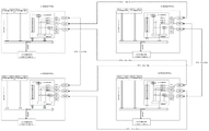
FIG. 3 is a flow chart of the input and output of a typical digitized reactor protection system for a nuclear power plant
FIG. 4 is a flow chart of typical digitized reactor protection system channel communication for a nuclear power plant
Detailed Description
The invention mainly comprises the following steps:
establishing a zero-dimensional repair zero test reactor protection system fault tree model taking control rod power failure caused by tripping of a shutdown breaker as a top event;
establishing boundary conditions of corresponding tests according to regular test procedures of a reactor protection system;
establishing a temporary boundary condition aiming at the system configuration state change caused by the defect or defect maintenance of a reactor protection system;
calculating a first-order cut set related device obtained by a zero maintenance zero test fault tree model as an SPV device;
selecting corresponding boundary conditions to establish a boundary condition set according to the current test and the existing defects of the reactor protection system or the maintenance aiming at the defects, calculating a fault tree under the boundary conditions to obtain a new first-order cut set, comparing the new first-order cut set with the first-order cut set obtained by a fault tree model of the zero-dimensional zero-repairing test, and taking the equipment corresponding to the new first-order cut set as the temporary SPV of the system under the current state.
The following description is made in conjunction with the following specific examples and accompanying drawings:
the first step firstly needs to determine the analysis boundary of the digital reactor protection system malfunction fault tree: taking a typical digital reactor protection system as an example, the outer boundary of the system comprises a shutdown circuit breaker serving as an actuating mechanism, a digital reactor protection system computer, a signal processing cabinet and an on-site transmitter; the inner boundary is a functional clamping piece in each cabinet.
And secondly, establishing a fault tree model taking control rod power loss caused by tripping of a shutdown breaker as a top event, wherein the specific process comprises the following steps:
1. drawing a system diagram within the analysis range of the fault tree, taking a typical digital reactor protection system as an example, and comprising: the number of the shutdown circuit breakers serving as the execution mechanism is eight, the shutdown circuit breakers are divided into four channels, each channel is provided with two circuit breakers, and a logic of taking four channels and taking two channels to shutdown is realized through a special connection mode, as shown in the figure two; the instrument control part comprises a local transmitter, an analog signal conditioning module SAA1, a platinum resistance signal conversion module STT1, a standard signal expansion module SNV1, an overvoltage protection module SOB1, a switching value signal conditioning module SBC1, an analog signal input module SAI1, a switching value input module SDI1, a CPU module SVE2, a communication module SL22, a photoelectric conversion module SLM2, a switching value output module SDO1 and a relay module SRB1, wherein the logic calculation part of each channel has two independent subgroups as shown in the figure III; the four channels communicate with each other through optical fibers, and signal transmission is only carried out in the corresponding sub-groups, as shown in the fourth drawing; each channel will have either 2/4 logic or 2/3 logic (relative to the number of channels of the local transmitter) for the trip signal.
2. A fault tree model is established with the control rod power loss caused by tripping of the shutdown breaker as the top event, and shutdown signals are exemplified by low main pump rotation speed (subgroup a, field transmitter is 3 channels) and tripping of the main pump (subgroup b, field contact is 4 channels).
And thirdly, calculating the top event of the fault tree obtained in the second step, setting first-order truncation during calculation to obtain a plurality of first-order cut sets, wherein the equipment corresponding to the basic events of the first-order cut sets is the SPV equipment of the digital reactor protection system.
And fourthly, establishing a boundary condition for calculating the temporary SPV of the digital reactor protection system, and setting all basic events in the first-order cut set obtained by calculation in the third step as FALSE, namely, the basic events are considered to be basically not generated when the temporary SPV is calculated, and calculating the fault tree top event under the boundary condition without the first-order cut set.
And fifthly, establishing the corresponding fault tree boundary conditions of the reactor protection system periodic tests so as to carry out rapid system state configuration during the periodic tests. Taking the general configuration of the reactor protection system during the test as an example, the corresponding boundary conditions are established as follows:
1. according to the test rule, the reactor protection system test is to transmit a single trip circuit breaker tripping signal one by one through an engineer station to verify the action condition of the trip circuit breaker, so the test is divided into eight configuration states which are eight trip circuit breaker tripping states respectively;
2. when a trip test of a 1# shutdown breaker is carried out, two gates of a 1-YFTB-A1-SVE2-A-Q1 shutdown protection system A1 channel diversity a processor module output Q1 trip signal and a 1-YFTB-A1-SVE2-B-Q1 shutdown protection system A1 channel diversity B processor module output Q1 trip signal in a corresponding fault tree are true, so that the boundary conditions are set as follows:
1-YFTB-A1-SVE2-A-Q1 TRUE
1-YFTB-A1-SVE2-B-Q1 TRUE
similarly, when the trip test of the 2# shutdown breaker is carried out, the boundary conditions are set as follows:
1-YFTB-A1-SVE2-A-Q2 TRUE
1-YFTB-A1-SVE2-B-Q2 TRUE
when the trip test of the 3# shutdown breaker is carried out, the boundary conditions are set as follows:
1-YFTB-A2-SVE2-A-Q3 TRUE
1-YFTB-A2-SVE2-B-Q3 TRUE
when the trip test of the 4# shutdown breaker is carried out, the boundary conditions are set as follows:
1-YFTB-A2-SVE2-A-Q4 TRUE
1-YFTB-A2-SVE2-B-Q4 TRUE
when the trip test of the No. 5 shutdown breaker is carried out, the boundary conditions are set as follows:
1-YFTB-B1-SVE2-A-Q5 TRUE
1-YFTB-B1-SVE2-B-Q5 TRUE
when the trip test of the No. 6 shutdown breaker is carried out, the boundary conditions are set as follows:
1-YFTB-B1-SVE2-A-Q6 TRUE
1-YFTB-B1-SVE2-B-Q6 TRUE
when the 7# shutdown breaker tripping test is carried out, the boundary conditions are set as follows:
1-YFTB-B2-SVE2-A-Q7 TRUE
1-YFTB-B2-SVE2-B-Q7 TRUE
when the trip test of the 8# shutdown breaker is carried out, the boundary conditions are set as follows:
1-YFTB-B2-SVE2-A-Q8 TRUE
1-YFTB-B2-SVE2-B-Q8 TRUE
and sixthly, calculating the temporary SPV equipment under the current system configuration. And selecting corresponding boundary conditions according to the current test work of the system, selecting temporary SPV calculation boundary conditions at the same time, and calculating a device corresponding to a first-order cut set obtained by a fault treetop event, wherein the device is the temporary SPV device under the current system configuration.
Claims (8)
1. A method for identifying key sensitive equipment of a digital reactor protection system is characterized by comprising the following steps: the method comprises the following steps: determining a fault tree analysis boundary of the digital reactor protection system; step two: establishing a zero-dimensional zero-repairing test fault tree model taking control rod power failure caused by tripping of a shutdown breaker as a top event; step three: establishing boundary conditions of a fault tree corresponding to a periodic test of a reactor protection system; step four: step two and step three establish the real-time fault tree model of the digital reactor protection system together; step five: calculating the equipment corresponding to the first-order cut set basic event obtained by the fault tree model in the step two, and determining SPV equipment; step six: establishing a boundary condition for temporary SPV calculation of a digital reactor protection system; step seven: and step five and step six jointly calculate to obtain the temporary SPV equipment under the current system configuration.
2. The method for identifying the key sensitive equipment of the digital reactor protection system according to claim 1, wherein the method comprises the following steps: the first step is as follows: determining a fault tree analysis boundary of a digital reactor protection system malfunction, which specifically comprises the following steps: the outer boundary of the typical digital reactor protection system comprises a shutdown circuit breaker serving as an actuating mechanism, a digital reactor protection system computer, a signal processing cabinet and an on-site transmitter; the inner boundary is a functional clamping piece in each cabinet.
3. The method for identifying the key sensitive equipment of the digital reactor protection system according to claim 1, wherein the method comprises the following steps: the second step is that: the method comprises the following steps of establishing a zero-dimensional zero-repairing test fault tree model taking control rod power failure caused by tripping of a shutdown breaker as a top event, and specifically comprising the following steps of: drawing a system diagram in a fault tree analysis range; and establishing a fault tree model taking the trip of the shutdown breaker as a top event to cause the loss of power of the control rod.
4. The method for identifying the digital reactor key sensitive equipment as claimed in claim 1, wherein the method comprises the following steps: the third step is that: establishing a corresponding fault tree boundary condition for a reactor protection system periodic test, which specifically comprises the following steps: according to the test procedure, the configuration state is determined, and the boundary condition is set.
5. The method for identifying the digital reactor key sensitive equipment as claimed in claim 1, wherein the method comprises the following steps: the fourth step is that: step two and step three establish the real-time fault tree model of the digital reactor protection system together, include specifically: and embedding the boundary conditions set in the third step into the zero-dimensional zero-repairing test fault tree model in the second step, and selecting corresponding boundary conditions according to the real-time ongoing test of the power plant to obtain the real-time fault tree model of the digital reactor protection system.
6. The method for identifying the digital reactor key sensitive equipment as claimed in claim 1, wherein the method comprises the following steps: the fifth step is as follows: calculating the equipment corresponding to the first-order cut set basic event obtained by the fault tree model in the step two, and determining the SPV equipment, wherein the method specifically comprises the following steps: and calculating the top event of the fault tree obtained in the second step, and setting first-order truncation during calculation to obtain N (N is more than or equal to 1) first-order cut sets, wherein the equipment corresponding to the basic events of the N first-order cut sets is the SPV equipment of the digital reactor protection system.
7. The method for identifying the digital reactor key sensitive equipment as claimed in claim 1, wherein the method comprises the following steps: the sixth step is as follows: establishing a boundary condition for temporary SPV calculation of a digital reactor protection system, which specifically comprises the following steps: all basic events in the first cut set calculated in the step five are set as FALSE, that is, the basic events are considered not to occur when the temporary SPV is calculated, and no first cut set exists when the fault tree top event is calculated under the boundary condition.
8. The method for identifying the digital reactor key sensitive equipment as claimed in claim 1, wherein the method comprises the following steps: the seventh step: step five and step six jointly calculate to obtain the temporary SPV equipment under the current system configuration, and specifically comprise the following steps: and selecting corresponding boundary conditions according to the current test work of the system, selecting temporary SPV calculation boundary conditions at the same time, and calculating a device corresponding to a first-order cut set obtained by a fault treetop event, wherein the device is the temporary SPV device under the current system configuration.
Priority Applications (1)
| Application Number | Priority Date | Filing Date | Title |
|---|---|---|---|
| CN202111222715.8A CN114091237B (en) | 2021-10-20 | 2021-10-20 | Method for identifying key sensitive equipment of digital reactor protection system |
Applications Claiming Priority (1)
| Application Number | Priority Date | Filing Date | Title |
|---|---|---|---|
| CN202111222715.8A CN114091237B (en) | 2021-10-20 | 2021-10-20 | Method for identifying key sensitive equipment of digital reactor protection system |
Publications (2)
| Publication Number | Publication Date |
|---|---|
| CN114091237A true CN114091237A (en) | 2022-02-25 |
| CN114091237B CN114091237B (en) | 2024-08-09 |
Family
ID=80297292
Family Applications (1)
| Application Number | Title | Priority Date | Filing Date |
|---|---|---|---|
| CN202111222715.8A Active CN114091237B (en) | 2021-10-20 | 2021-10-20 | Method for identifying key sensitive equipment of digital reactor protection system |
Country Status (1)
| Country | Link |
|---|---|
| CN (1) | CN114091237B (en) |
Cited By (1)
| Publication number | Priority date | Publication date | Assignee | Title |
|---|---|---|---|---|
| CN115312225A (en) * | 2022-07-15 | 2022-11-08 | 苏州热工研究院有限公司 | Modeling method and system for shutdown and shutdown model of nuclear power plant |
Citations (6)
| Publication number | Priority date | Publication date | Assignee | Title |
|---|---|---|---|---|
| KR20080013153A (en) * | 2006-08-07 | 2008-02-13 | 삼창기업 주식회사 | Digital reactor protection system |
| JP2012008744A (en) * | 2010-06-23 | 2012-01-12 | Inst Nuclear Energy Research Rocaec | Risk quantitative assessment method by computer supported top logic for nuclear power plant |
| CN104850750A (en) * | 2015-05-27 | 2015-08-19 | 东北大学 | Nuclear power plant reactor protection system reliability analysis method |
| CN109358583A (en) * | 2018-10-23 | 2019-02-19 | 中核核电运行管理有限公司 | A method of preventing the failure of nuclear power unit key work center method |
| CN109521751A (en) * | 2018-10-23 | 2019-03-26 | 中核核电运行管理有限公司 | A kind of nuclear power plant's key work center method failure mitigation method |
| CN109559048A (en) * | 2018-12-02 | 2019-04-02 | 湖南大学 | A kind of system reliability estimation method of nuclear power equipment |
-
2021
- 2021-10-20 CN CN202111222715.8A patent/CN114091237B/en active Active
Patent Citations (6)
| Publication number | Priority date | Publication date | Assignee | Title |
|---|---|---|---|---|
| KR20080013153A (en) * | 2006-08-07 | 2008-02-13 | 삼창기업 주식회사 | Digital reactor protection system |
| JP2012008744A (en) * | 2010-06-23 | 2012-01-12 | Inst Nuclear Energy Research Rocaec | Risk quantitative assessment method by computer supported top logic for nuclear power plant |
| CN104850750A (en) * | 2015-05-27 | 2015-08-19 | 东北大学 | Nuclear power plant reactor protection system reliability analysis method |
| CN109358583A (en) * | 2018-10-23 | 2019-02-19 | 中核核电运行管理有限公司 | A method of preventing the failure of nuclear power unit key work center method |
| CN109521751A (en) * | 2018-10-23 | 2019-03-26 | 中核核电运行管理有限公司 | A kind of nuclear power plant's key work center method failure mitigation method |
| CN109559048A (en) * | 2018-12-02 | 2019-04-02 | 湖南大学 | A kind of system reliability estimation method of nuclear power equipment |
Non-Patent Citations (3)
| Title |
|---|
| 于文革, 张志俭, 黄卫刚, 王朝贵: "大亚湾核电站反应堆保护系统可靠性分析", 核动力工程, no. 01, 28 February 2003 (2003-02-28) * |
| 周海翔;王卫国;: "田湾核电站数字化反应堆保护系统可靠性分析", 核电子学与探测技术, no. 06, 20 November 2009 (2009-11-20) * |
| 龚渊: "秦山核电厂PSA模型开发及其应用前景展望", 《核工业第七届可靠性研究成果专刊论文集》, 30 June 2004 (2004-06-30) * |
Cited By (1)
| Publication number | Priority date | Publication date | Assignee | Title |
|---|---|---|---|---|
| CN115312225A (en) * | 2022-07-15 | 2022-11-08 | 苏州热工研究院有限公司 | Modeling method and system for shutdown and shutdown model of nuclear power plant |
Also Published As
| Publication number | Publication date |
|---|---|
| CN114091237B (en) | 2024-08-09 |
Similar Documents
| Publication | Publication Date | Title |
|---|---|---|
| CN110048507B (en) | Automatic inspection method and system for power distribution automation system | |
| CN110221198B (en) | Coal mine underground combination switch fault diagnosis method based on fault tree | |
| CN101666841B (en) | Fault diagnosis method of digitalizing transformer substation electronic transducer | |
| CN104246521B (en) | Method and device for automatic testing of relay protection function in smart substation | |
| CN114580177B (en) | Power system scheduling method based on cascading failure prevention | |
| CN108551401B (en) | Virtual-real loop correlation mapping and diagnosis method of virtual-real diagnosis system of intelligent substation | |
| CN103986238B (en) | Intelligent substation fault diagnosis method based on probability weighting bipartite graph method | |
| US9819196B2 (en) | Power distribution system capable of automatic fault detection in a distributed manner and method thereof | |
| CN109116181A (en) | A kind of fault detector failure judgment method based on maximum probability | |
| CN109949178B (en) | A Judgment and Completion Method for Power Outage Events in Medium Voltage Distribution Network Based on Support Vector Machine | |
| CN110085333B (en) | A protection system for small reactors | |
| CN112149877B (en) | Multi-source data driven fault prediction method and system for multi-element complex urban power grid | |
| CN110011414B (en) | Intelligent substation sampling loop fault judgment method based on homologous data comparison | |
| CN114091237A (en) | Method for identifying key sensitive equipment of digital reactor protection system | |
| CN108336817A (en) | Digital distribution system | |
| CN114167217B (en) | Multiple fault diagnosis method for railway distribution network | |
| CN116106733A (en) | A method and system for confirming the position of an isolating switch | |
| CN106300293B (en) | A kind of complex fault based on power system bottom fault message incorporates in series method | |
| CN119253552A (en) | Snowflake distribution network self-healing processing logic optimization method, system, device and medium | |
| Xue et al. | Approach for studying the impact of communication failures on power grid | |
| Zong et al. | A method of fault diagnosis for secondary loop in intelligent substation based on Bayesian algorithm | |
| CN110021933A (en) | Consider the power information system control function reliability estimation method of component faults | |
| Amjadi et al. | IEC61850 GOOSE performance in real time and challenges faced by power utilities | |
| CN110854826B (en) | A fault diagnosis and treatment method for a three-out-two protection system of a flexible DC converter valve | |
| CN120545917B (en) | Relay protection interlocking control method based on fault whole process prediction |
Legal Events
| Date | Code | Title | Description |
|---|---|---|---|
| PB01 | Publication | ||
| PB01 | Publication | ||
| SE01 | Entry into force of request for substantive examination | ||
| SE01 | Entry into force of request for substantive examination | ||
| GR01 | Patent grant | ||
| GR01 | Patent grant |