Fog dispersal device system and fog dispersal method based on combined action of detonation waves and positive and negative charged particles
Technical Field
The invention relates to an artificial fog dispersal device, in particular to a fog dispersal device system based on the combined action of detonation waves and positive and negative charged particles, and also relates to an artificial fog dispersal method, in particular to a fog dispersal method based on the combined action of detonation waves and positive and negative charged particles, and belongs to the technical field of artificial influence on weather.
Background
With the rapid development of social economy in China, the influence of heavy fog weather on traffic transportation safety production is greater and greater, and the loss caused by heavy fog weather is also more and more serious. For example, in 2016, 11, 4 days in the morning, in Wuhan, Hubei province, at a high speed, in Wuhan, the direction of the yellow stone is 31.4 kilometers, and the traffic accident that three large trailers collide with each other is caused by the fog. In 11/10/2018, in foggy weather and in rainy road surface icing on the day before, 33 vehicle-linked collisions accidents of multiple casualties occur in the Shanxi long and high-speed Xiangyuan king village viaduct section, 7 trapped persons are found after rescue by fire rescue workers for nearly two hours, and are sent to hospitals for rescue by emergency vehicles. At present, fog prevention and control are generally carried out in two ways, one is preventive measures, such as issuing a fog early warning, closing a fog-affected road section, closing an airport, an automobile restriction and the like, and the other is treatment measures, namely achieving the fog elimination effect through manual weather-affecting technical measures.
In autumn and winter in China, heavy fog weather often occurs, the distribution height is generally below 1km, and the heavy fog weather is divided into cold fog (t is less than 0 ℃) and warm fog (t is more than or equal to 0 ℃) according to the temperature. According to the properties of the fog, the warm fog is generally absorbed by hygroscopic particles, such as hygroscopic salts like calcium chloride and sodium chloride, and the hygroscopic particles are enlarged and settled; or mechanical disturbance method such as stirring with propeller of helicopter at fog top to generate up-down convection to disperse fog; or heating evaporation method is adopted, and dry warm air is produced by using a jet engine to evaporate the fog drops. The supercooled fog is eliminated mainly by means of the Beijilong process, and when ice crystal, supercooled water drop and water vapor coexist, the saturated water vapor pressure on the ice surface is lower than that on the water surface, so that the water vapor is converted from the supercooled water drop to the ice crystal continuously to evaporate the supercooled water drop. The cold fog elimination is generally realized by the way that an airplane scatters artificial ice nucleuses, liquid nitrogen, dry ice and the like in the fog.
The related patent documents: CN112495103A discloses fog and haze eliminating operation system and method based on aircraft platform, and the system includes: the airplane comprises an airplane, a hygroscopic dry powder spreading device and an in-line flare hanging device, wherein the hygroscopic dry powder spreading device and the in-line flare hanging device are carried on the airplane; the in-line flare carrying device comprises an ignition controller, a flare fixing frame and a plurality of catalyst flares, wherein the flare fixing frame is fixedly connected to an airplane through a supporting and fixing arm, the catalyst flares are uniformly arranged on the flare fixing frame, and the ignition controller is connected with the catalyst flares through a cable. The technology overcomes the problems and the defects in the existing haze eliminating operation, the aircraft is adopted as a platform to carry out aerial operation, two kinds of equipment for eliminating cold and warm fog are carried, the function integration is realized, the cost is high, and the problem that the aircraft cannot take off due to weather reasons is solved. CN111420803A discloses a demisting and water collecting device with positive and negative ion charge and alternating current electric field combined collision, which comprises a positive ion charge module, a negative ion charge module, a charge ion collision module, a water collecting pipe and a water collecting tank; the positive ion charging module generates positive ions to charge the fog drops positively; the negative ion charging module generates negative ions to charge the fog drops negatively; the charged ion collision module generates an alternating current electric field, so that positive and negative charged fog drops collide and coalesce under the action of the alternating current electric field, and large liquid drops are formed and flow into the water collecting tank through the water collecting pipe; the ground electrode is arranged at the inlet of the water collecting pipe, so that charged fog drops which are not condensed into large liquid drops move to the ground electrode under the action of the negative direct-current high-voltage electrode, and the large liquid drops formed on the ground electrode flow into the water collecting tank through the water collecting pipe. The technology has the defects of short acting distance, small range and the like, and can not be applied to the heavy fog with thickness and range exceeding the device. CN111424603A discloses an acoustoelectric integrated airport defogging system and an airport defogging method, including: a three-electrode fog blocking device and a sound wave defogging device; the three-electrode fog blocking device comprises: the system comprises a control module, a power supply module, a plurality of electrode modules and two visibility meters, wherein the electrode modules are spliced along runways on two sides of runways of an airport; the electrode module is used for generating ion wind which points to the outside from the inside of the airport runway through corona discharge so as to intercept fog outside the airport runway; the two visibility meters are respectively used for measuring the visibility inside and outside the airport runway, and the control module is used for adjusting the voltage of the power supply module according to the visibility difference inside and outside the airport runway so as to adjust the intensity of the ion wind; the sound wave defogging device can move in the runway of the airport and is used for generating sound waves, enhancing collision and reunion among fog drops and improving the visibility in the runway of the airport. The technology has the defects of unclear fog-dispersing physical mechanism, unobvious effect and the like.
The cold and warm fog eliminating mode has the following defects: the aircraft operation and the heating evaporation method have higher cost, the influence range of the mechanical stirring method is limited, the fog dispersal physical mechanism and the effect of the sound-electricity integrated fog dispersal system are not clear, and the distance and the range of the sound-electricity integrated fog dispersal system are short and small only depending on positive and negative charged particles.
Disclosure of Invention
Aiming at the defects and the improvement requirements of the prior art, the invention aims to provide a fog dispersal device system based on the combined action of detonation waves and positive and negative charged particles, so as to solve the problems of unobvious fog dispersal effect, short action distance, small range and the like of a single method of detonation waves and positive and negative charged particles.
To this end, it is another object of the present invention to provide a method for defogging based on the combined action of detonation waves and positively and negatively charged particles.
In order to solve the technical problems, the technical scheme adopted by the invention is as follows:
a fog dispersal device system based on the combined action of detonation waves and positive and negative charged particles (electric ions) is provided with a remote control system, and the technical scheme is that the fog dispersal device system based on the combined action of the detonation waves and the positive and negative charged particles is also provided with a detonation wave generating device used for generating the detonation waves, a positive and negative charged particle generating device and an emission barrel used for emitting the detonation waves and the positive and negative particles; the positive and negative charged particle generating device is used for generating positive and negative charges to respectively charge the fog drops outside the launching tube with positive and load electricity.
The detonation wave generating device is provided with an ignition mechanism for ignition, a detonation chamber, an air storage tank filled with air, a fuel gas storage tank filled with combustible gas, a first valve and a second valve; the ignition mechanism is provided with an ignition chamber and a spark plug arranged in the ignition chamber; the detonation chamber and the ignition chamber are of a closed shell structure, and an air inlet of the ignition chamber is connected with an air outlet of the air storage tank through a first valve; the other air inlet of the ignition chamber is connected with an air outlet of the fuel gas storage tank through a second valve; the gas outlet of the ignition chamber is connected with the gas inlet of the detonation chamber, and the gas outlet of the detonation chamber is connected with the gas inlet of the launch canister to launch the generated detonation waves.
The positive and negative charged particle generating device is provided with a direct-current high-voltage power supply system (also called as a direct-current high-voltage power supply) for generating positive charges and negative charges through air discharge, a positive electrode matrix, a negative electrode matrix, a positive electrode connecting switch, a negative electrode connecting switch and two grounding electrode matrixes, namely a first grounding electrode matrix and a second grounding electrode matrix, wherein the direct-current high-voltage power supply system provides a high-voltage direct-current power supply for the positive electrode matrix and the negative electrode matrix, the positive electrode connecting switch and the negative electrode connecting switch are essentially control switches, the direct-current high-voltage power supply system is respectively connected with the positive electrode matrix and the negative electrode matrix through the positive electrode connecting switch and the negative electrode connecting switch, and when the direct-current power supply of the direct-current high-voltage power supply system is boosted to a certain degree, the air discharge generates the positive charges and the negative charges. The emitting tube comprises a positive electrode matrix, a negative electrode matrix, a first grounding electrode matrix and a second grounding electrode matrix which are longitudinally arranged oppositely and fixedly arranged in the emitting tube, wherein the positive electrode matrix and the negative electrode matrix are positioned between the first grounding electrode matrix and the second grounding electrode matrix, the positive electrode matrix and the negative electrode matrix are separated by insulators, and the first grounding electrode matrix and the second grounding electrode matrix are grounded through outgoing lines respectively.
In the above technical solution of the fog dispersal device system, a preferable technical solution may be that the detonation wave generating device further comprises an air compressor, and an air outlet of the air compressor is connected to an air inlet of the air storage tank through a pipeline. The air compressor is used to generate air that is delivered to the air storage tank 108 for storage. The above-mentioned detonation wave generating device preferably further has a flame arrester installed on a pipe connecting the air inlet of the ignition chamber and the air outlet of the gas storage tank and located between the second valve and the ignition chamber, so that the gas (liquefied gas) that is the gas to be transported enters the flame arrester, and the flame arrester transports the gas to the ignition chamber through the pipe. The flame arrester prevents the flame in the ignition chamber from entering the gas storage tank, and can only enter the detonation chamber in a single direction (so as to generate detonation waves). The structure of the positive electrode matrix, the negative electrode matrix, the first grounding electrode matrix and the second grounding electrode matrix which are all fixedly arranged in the launcher is preferably that the barrel body of the launcher is thick at the top and thin at the bottom, the cross section of the barrel body is rectangular (or square), the positive electrode matrix and the negative electrode matrix which are oppositely arranged are positioned in the middle (radial) of the inner cavity of the launcher, the electrode frames of the positive electrode matrix and the negative electrode matrix are fixedly arranged on the front inner side wall and the rear inner side wall of the launcher, and the electrode frame of the first grounding electrode matrix and the electrode frame of the second grounding electrode matrix are fixedly arranged on the left inner side wall and the right inner side wall of the launcher. The outer side wall of the ignition chamber preferably has a plurality of radiating fins, and the plurality of radiating fins are preferably uniformly distributed. The structure that the air outlet of the ignition chamber is connected with the air inlet of the detonation chamber is that the air outlet of the ignition chamber is preferably connected with the air inlet of the detonation chamber through a metal hose and a flange joint. In this way, the movement of the detonation chamber is not restricted; the combustible gas in the gas storage tank is preferably liquefied petroleum gas (the liquefied petroleum gas can be gaseous liquefied petroleum gas).
A fog dispersal method based on the combined action of detonation waves and positive and negative charged particles adopts the technical scheme that the fog dispersal device system is used, the detonation waves are utilized to generate shock waves and high-temperature and high-pressure air flows, the positive and negative charged particles are diffused to a fog area, firstly, a part of small fog drops are evaporated by the high-temperature air flows, then, the shock waves and the positive and negative charged particles cause the large fog drops to quickly collide and mutually adsorb to enlarge and fall to the ground, and the aim of quickly dispersing fog is fulfilled. The fog dispersal method specifically comprises the following steps:
and S1, acquiring meteorological data and judging whether the meteorological data meet fog dispersal operation conditions or not.
And S2, presetting a working area and height according to the wind direction and the wind speed and the concentration and the thickness of the fog.
And S3, performing operation preparation and ground test operation, adjusting azimuth and elevation of the launching tube (the azimuth and elevation of the launching tube connected with the detonation chamber can be adjusted by an adjusting mechanism according to the position of the fog region or the operation target region), connecting the direct-current high-voltage power supply system, and evacuating personnel from the site.
S4, according to the preset operation area, successively starting the detonation wave and positive and negative charged particle generating device to carry out fog dissipation operation, namely, starting the first valve, the second valve, a control switch of a high-voltage circuit for supplying power to the spark plug, a positive electrode connecting switch and a negative electrode connecting switch, generating shock waves, high-temperature and high-pressure air flows by using the detonation waves, diffusing the positive and negative charged particles to a fog area, evaporating a part of small fog drops by the high-temperature air flows, and then causing the large fog drops to rapidly collide and mutually adsorb and grow to land on the ground by the shock waves and the positive and negative charged particles to achieve the purpose of rapid fog dissipation.
And S5, judging the next operation time according to the visibility change trend, and continuing to operate until the visibility meets the current operation target.
And S6, performing operation effect evaluation and analysis on the current operation condition, and generating a fog dispersal operation record. In the above technical solution of the fog dispersal method, a preferable technical solution may be that the detonation wave is used to generate the shock wave, and the propagation speed of the detonation wave at the outlet of the launch canister is preferably 1800m/s, for the high-temperature and high-pressure airflow, the airflow temperature at the outlet of the launch canister is preferably 2000-3000k, and the air pressure is preferably 0.8-2.0 Mpa; the frequency of occurrence of detonation waves is preferably 6-8 seconds/time. Generating a primary detonation wave, wherein the opening time of the first valve, namely the time for filling air into the ignition chamber, is 4-5 seconds, the opening time of the second valve, namely the time for filling combustible gas into the ignition chamber, is 5-6 seconds, the filling rate of the combustible gas is 0.5-0.9 g/s, and the ratio of the mass of the air filled into the ignition chamber to the mass of the combustible gas filled into the ignition chamber is (5-9): 1; after the combustible gas is filled for 1-2 seconds, a control switch of a high-voltage circuit for supplying power to the spark plug is turned on. In the step S1, the obtaining of the weather data and the determining of whether the weather data satisfies the fog dispersal operation condition preferably include: acquiring horizontal visibility data according to a meteorological detection means, and judging whether fog dispersal operation conditions are met or not according to the data; the horizontal visibility is less than 1000m, and fog dispersal operation conditions are met. In the fog dispersal method, a catalyst generated by the combustion of the cold cloud/warm cloud flame strips can be introduced into the launch canister or introduced onto a path where the detonation waves and the positive and negative charged particles move, and the detonation waves, the positive and negative charged particles and the catalyst act together to dissipate fog (so as to achieve the aim of dissipating fog). The single device system is suitable for fog weather generated under the condition of calm and steady weather, a plurality of defense lines are required to be additionally arranged for advection fog, and a plurality of device equipment are arranged on each defense line to realize combined fog dissipation operation, so that an obvious fog dissipation effect can be obtained.
When the detonation wave is launched, the outlet of the launching tube is aligned to the position to be operated by adjusting the shooting direction and the shooting angle of the detonation chamber and the launching tube. Opening the first valve on the pipeline between air storage tank and the ignition mechanism, during air admission ignition mechanism's the ignition chamber, then in getting into the detonation chamber from the ignition chamber, opening the second valve on the pipeline between gas storage tank (also called liquefied gas jar) and the ignition mechanism, liquefied gas in the gas storage tank gets into the spark arrester, and then in getting into ignition mechanism's the ignition chamber, then combustible gas (liquefied gas) get into inside the detonation chamber from the ignition chamber. And starting the ignition mechanism, opening a control switch of a high-voltage circuit for supplying power to the spark plug, igniting combustible gas (liquefied gas) in the spark plug, and burning flame into the detonation chamber so as to ignite the combustible gas (liquefied gas) and air mixed gas in the detonation chamber. Deflagration is generated in the detonation chamber, so that the internal air pressure is increased to generate shock waves, the shock waves enter the launching tube, and the shock waves are ejected from the air outlet of the launching tube to launch detonation waves to a large fog area (a fog area, an operation target area). The positive and negative charges (positive and negative charges) generated by the positive and negative charged particle generating device are transferred to the fog area through the detonation wave band to enable the fog drops to respectively carry positive and negative charges, so that the aim of fast fog dissipation is fulfilled.
In summary, the present invention provides a fog dispersal device system and a fog dispersal method based on the combined action of detonation waves and positive and negative charged particles, and compared with the prior art, the technical scheme of the present invention combines the two advantages of detonation waves and positive and negative charged particles, and the present invention obtains the following technical effects: (1) firstly, evaporating a part of small fog drops by high-temperature airflow, and then causing the large fog drops to quickly collide, mutually adsorb and enlarge by shock waves and positive and negative charged particles to fall to the ground (the physical mechanism of fog dissipation is clear); (2) the large fog area with the action linear distance not less than 1900m and the coverage range not less than 2.835 square kilometers can be acted, and the large fog area has the advantages of large action distance and wide range; (3) the remote control operation of the air storage tank, the gas storage tank (liquefied gas tank), the direct-current high-voltage power supply and the remote control system is used, and the remote control device has the advantages of strong operability, low cost, good fog dissipation effect and the like.
The fog dispersal device system and the method can play two independent functions of detonation waves and positive and negative charged particles, have large action distance and wide range, can be used for ensuring large-scale activities, such as fog dispersal requirements of airports, expressways, ports, scenic spots and the like, and have the advantages of strong operability, low cost, good fog dispersal effect and the like.
Drawings
Fig. 1 is a schematic structural diagram of a fog dispersal device system based on the combined action of detonation waves and positive and negative charged particles.
FIG. 2 is a schematic structural diagram of a detonation wave generating device according to the present invention.
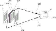
Fig. 3 is a schematic structural diagram of the positive and negative charged particle generating device according to the present invention.
Fig. 4 is a control schematic diagram of the remote control system of the present invention.
Detailed Description
In order to make the objects, technical solutions and advantages of the present invention more clear, the technical solutions of the present invention will be clearly and completely described below with reference to the accompanying drawings and embodiments. Embodiments 1-2 are a fog dispersal device system and a fog dispersal method based on the combined action of detonation waves and positive and negative charged particles. It is to be understood that the described embodiments are merely exemplary of the invention, and not restrictive of the full scope of the invention. All other embodiments, which can be obtained by a person skilled in the art without any inventive step based on the embodiments of the present invention, belong to the protection scope of the present invention (the technical features involved in the embodiments of the present invention described below can be combined with each other as long as they do not conflict with each other).
Example 1: as shown in fig. 1, 2, 3 and 4, the fog dispersal device system based on the combined action of detonation waves and positive and negative charged particles (electric ions) of the present invention has a remote control system 4, a detonation wave generating device 1 for generating detonation waves, a positive and negative charged particle generating device 2, and an emitter barrel 3 for emitting the detonation waves and the positive and negative particles. The positive and negative charged particle generating device is used for generating positive and negative charges to respectively charge the fog drops outside the launching tube with positive and load electricity.
As shown in fig. 1, 2, 3, and 4, the detonation wave generating device 1 includes an ignition mechanism 100 for ignition, a detonation chamber 101, an air tank 108 containing air, a gas tank 109 containing combustible gas, a first valve 106, and a second valve 110. The ignition mechanism 100 has an ignition chamber 104, and an ignition plug 103 mounted in the ignition chamber 104. The detonation chamber 101 and the ignition chamber 104 are of a closed shell structure, and both can be made of steel plates, and an air inlet of the ignition chamber 104 is connected with an air outlet of the air storage tank 108 through a first valve 106 (the first valve is installed on the pipeline). The other inlet of the ignition chamber 104 is connected to the outlet of the gas storage tank 109 via a second valve 110 (the second valve is mounted on the pipeline). The gas outlet of the ignition chamber 104 is connected with the gas inlet of the detonation chamber 101, and the gas outlet of the detonation chamber 101 is connected with the gas inlet of the launch canister 3 to launch the generated detonation waves.
As shown in fig. 1, 2, 3, and 4, the positively and negatively charged particle generating apparatus 2 includes a dc high voltage power supply system 201 (the dc high voltage power supply system is also referred to as a dc high voltage power supply) for generating positive charges 209 and negative charges 210 by air discharge, a positive electrode matrix 206, a negative electrode matrix 207, a positive electrode connecting switch 202, a negative electrode connecting switch 203, two ground electrode matrices, i.e., a first ground electrode matrix 205 and a second ground electrode matrix 204. The dc high voltage power system 201 provides high voltage dc power for the positive and negative electrode matrix, and the positive electrode connection switch 202 and the negative electrode connection switch 203 are essentially control switches. The dc high-voltage power supply system 201 is connected to a positive electrode matrix 206 and a negative electrode matrix 207 respectively through a positive electrode connection switch 202 and a negative electrode connection switch 203 (a cable 208' is connected to the positive electrode connection switch and the negative electrode connection switch, and connectors are provided at the ends of the positive electrode matrix and the negative electrode matrix), and when the dc power supply of the dc high-voltage power supply system is boosted to a certain degree, the dc high-voltage power supply system discharges air to generate positive charges 209 and negative charges 210. The positive electrode matrix 206, the negative electrode matrix 207, the first grounding electrode matrix 205 and the second grounding electrode matrix 204 are arranged oppositely in the longitudinal direction and are fixedly installed in the emission barrel 3, the positive electrode matrix 206 and the negative electrode matrix 207 are located between the first grounding electrode matrix 205 and the second grounding electrode matrix 204, the positive electrode matrix 206 and the negative electrode matrix 207 are separated by an insulator 208, and the first grounding electrode matrix 205 and the second grounding electrode matrix 204 are grounded through lead wires respectively. A voltage difference exists between the positive electrode matrix and the negative electrode matrix and the grounding electrode matrix, so that corona discharge is generated.
As shown in fig. 1, 2, 3, and 4, the detonation wave generator 1 further includes an air compressor 107, and an air outlet of the air compressor 107 is connected to an air inlet of an air storage tank 108 through a pipeline. The air compressor 107 is used to generate air that is delivered to the air storage tank 108 for storage. The above-mentioned detonation wave generating apparatus 1 preferably further has a flame arrester 111, and the flame arrester 111 is installed on a pipeline connecting an air inlet of the firebox 104 and an air outlet of the gas storage tank 109 and is located between the second valve 110 and the firebox 104, so that gas (liquefied gas) as a combustible gas enters the flame arrester, and the flame arrester delivers the gas to the firebox through the pipeline. The positive electrode matrix 206, the negative electrode matrix 207, the first ground electrode matrix 205, and the second ground electrode matrix 204 are all fixedly mounted in the launch canister 3, and the launch canister 3 has a rectangular (or square) cross section with a thick top and a thin bottom, and may be made of a steel plate (or a non-metal plate). The positive electrode matrix 206 and the negative electrode matrix 207 which are oppositely arranged are positioned in the middle (radial direction) of the inner cavity of the launch barrel 3, the electrode frame of the positive electrode matrix 206 and the electrode frame of the negative electrode matrix 207 are fixedly arranged on the front inner side wall and the rear inner side wall of the launch barrel 3, and the electrode frame of the first grounding electrode matrix 205 and the electrode frame of the second grounding electrode matrix 204 are fixedly arranged on the left inner side wall and the right inner side wall of the launch barrel 3. The ignition chamber 104 has a plurality of fins 105 on an outer sidewall thereof, and the plurality of fins are preferably uniformly distributed. The outlet of the ignition chamber 104 is connected to the inlet of the detonation chamber 101, and the outlet of the ignition chamber 104 is connected to the inlet of the detonation chamber 101 through a metal hose 102 and a flange joint. Thus, the movement of the detonation chamber 101 is not restricted; the combustible gas contained in the gas storage tank 109 is liquefied petroleum gas (the liquefied petroleum gas may be gaseous liquefied petroleum gas). As shown in fig. 3, the positive electrode matrix 206, the negative electrode matrix 207, the first ground electrode matrix 205 and the second ground electrode matrix 204 may have the same structure, and are all mesh-shaped electrodes made of galvanized sheet metal mesh coated with a hydrophobic agent, and the insulator 208 is made of nylon material, and is configured as a zigzag mesh structure to increase creepage distance. The front and rear ends of the insulator 208 may be fixedly connected to the front and rear inner side walls of the launch barrel 3, or may be fixedly connected to the electrode frames of the positive electrode matrix 206 and the negative electrode matrix 207.
As shown in fig. 1, 2, 3, and 4, when detonation wave is emitted, the firing angle and the firing angle of the detonation chamber 101 and the launch barrel 3 are adjusted so that the outlet of the launch barrel 3 is aligned with the position where work is to be performed. The first valve 106 on the pipeline between the air storage tank 108 and the ignition mechanism 100 is opened, air enters the ignition chamber 104 of the ignition mechanism, then enters the detonation chamber 101 from the ignition chamber 104, the second valve 110 on the pipeline between the gas storage tank 109 (the gas storage tank is also called as a liquefied gas tank) and the ignition mechanism is opened, liquefied gas in the gas storage tank 109 enters the flame arrester, then enters the ignition chamber 104 of the ignition mechanism, and then combustible gas (liquefied gas) enters the detonation chamber 101 from the ignition chamber 104. The ignition mechanism is started, the control switch 113 of the high-voltage circuit for supplying power to the spark plug 103 is turned on, the spark plug 103 ignites the combustible gas (liquefied gas) inside the spark plug 103, and the flame is burned into the detonation chamber 101, so that the combustible gas (liquefied gas) and the air mixed gas inside the detonation chamber 101 are ignited. The detonation is generated inside the detonation chamber 101, so that the internal air pressure is increased to generate shock waves, the shock waves enter the interior of the launching tube 3, and the shock waves are ejected from the air outlet of the launching tube 3 to be launched into a large fog area D, namely a working target area (fog area). The positive charge and the negative charge generated by the positive charged particle generating device and the negative charged particle generating device are brought to a fog area through detonation waves, so that fog drops are respectively provided with positive charges and negative charges, and the aim of fast fog dissipation is fulfilled.
Example 2: as shown in fig. 1, 2, 3, and 4, the fog dispersal method based on the combined action of detonation waves and positive and negative charged particles of the present invention uses the fog dispersal device system of the above embodiment 1, uses the detonation waves to generate shock waves and high-temperature and high-pressure air flows, diffuses the positive and negative charged particles into fog areas, firstly the high-temperature air flows evaporate a part of small fog droplets, and then the shock waves and the positive and negative charged particles cause the large fog droplets to rapidly collide and mutually adsorb to enlarge and fall to the ground, so as to achieve the purpose of rapid fog dispersal. The fog dispersal method specifically comprises the following steps:
and S1, acquiring meteorological data and judging whether the meteorological data meet fog dispersal operation conditions or not.
And S2, presetting a working area and height according to the wind direction and the wind speed and the concentration and the thickness of the fog.
And S3, performing operation preparation and ground test operation, adjusting azimuth and elevation angles of the launching tube (the azimuth and elevation angles of the launching tube 3 connected with the detonation chamber 101 can be adjusted by an adjusting mechanism according to the position of the fog region or the operation target region), connecting the direct-current high-voltage power supply system 201, and evacuating personnel from the site.
S4, according to the preset operation area, successively starting the detonation wave and positive and negative charged particle generating device to carry out fog dissipation operation, namely starting the first valve 106, the second valve 110, the control switch 113 of the high-voltage circuit for supplying power to the spark plug, the positive electrode connecting switch 202 and the negative electrode connecting switch 203, generating shock waves, high-temperature and high-pressure air flows by using the detonation waves, diffusing the positive and negative charged particles to a fog area, evaporating a part of small fog drops by the high-temperature air flows, and then causing the large fog drops to rapidly collide and mutually adsorb to be enlarged and fall to the ground by the shock waves and the positive and negative charged particles to achieve the purpose of rapid fog dissipation.
And S5, judging the next operation time according to the visibility change trend, and continuing to operate until the visibility meets the current operation target.
And S6, performing operation effect evaluation and analysis on the current operation condition, and generating a fog dispersal operation record. The detonation wave is utilized to generate the shock wave, and the propagation speed of the detonation wave, i.e. the shock wave at the outlet of the launch canister, is 1800m/s plus 600-1200 m/s, and in this embodiment, 1200m/s plus 1000-1200m/s is selected. For the high-temperature and high-pressure airflow, the airflow temperature at the outlet of the launching tube is 2000-3000k, 2200-2500k can be selected, and the air pressure is 0.8-2.0MPa and 1.5-1.8 MPa. The occurrence frequency of the detonation waves (i.e., the duration of the detonation waves generated once) is 6 to 8 seconds/time. The opening time of the first valve 106, i.e., the time for filling the ignition chamber 104 with air, is 4-5 seconds, preferably 5 seconds. The opening time of the second valve 110, i.e., the time for charging the ignition chamber 104 with the combustible gas (liquefied gas), is 5 to 6 seconds, preferably 6 seconds. The combustible gas aeration rate is 0.5-0.9 g/s, preferably 0.7 g/s. The ratio of the mass of air filled in the ignition chamber 104 to the mass of combustible gas filled in the ignition chamber is (5-9): 1, and 8:1 or 7:1 is selected. After the combustible gas is filled for 1-2 seconds (2 seconds is selected), the control switch 113 of the high-voltage circuit for supplying power to the spark plug is turned on. Thus, the amount of combustible gas (liquefied gas) used (the amount of aeration) was 4.2 g (usually 2.5 to 5.4 g), the mass of aerated air was 29.4 g, and the ratio of the two masses was 7:1, and the aeration rate of air was 5.88 g/sec. In the step S1, obtaining weather data, and determining whether the weather data satisfies fog dispersal operation conditions specifically includes: acquiring horizontal visibility data according to a meteorological detection means, and judging whether fog dispersal operation conditions are met or not according to the data; the horizontal visibility is less than 1000m, and fog dispersal operation conditions are met. The invention can also introduce the catalyst generated by the combustion of the cold cloud/warm cloud flare into the launching tube or into the path of the detonation wave and the positive and negative charged particles, and the detonation wave, the positive and negative charged particles and the catalyst act together to dissipate fog (achieve the aim of dissipating fog). The single device system is suitable for fog weather generated under the condition of calm and steady weather, a plurality of defense lines are required to be additionally arranged for advection fog, and a plurality of device equipment are arranged on each defense line to realize combined fog dissipation operation, so that an obvious fog dissipation effect can be obtained.
The present invention can give full play to the detonation wave and the positive and load electric particles, and has great acting distance and wide range. The action linear distance of the device system is not less than 1900m and the coverage area is not less than 2.835 square kilometers in the fog area (calculation formula: pi r)2And/4, quarter circle area with the bottom of the launching tube as the origin and the acting distance as the radius). The detonation wave generator 1 may be disposed in the space body 112, and the space body 112 may be a rectangular parallelepiped housing. The air inlet of the launching tube 3 extends into the space body 112 and is connected with the air outlet of the detonation chamber 101. Far awayThe control system 4 itself is a conventional technology, and the remote control system 4 includes a control terminal 401 (a control terminal, i.e. a computer terminal), a server 402 (a monitoring center), an integrated controller a installed on the space body 112, an integrated controller B installed on the outer shell of the dc high-voltage power supply system 201, and a node controller a1Node controller A2Node controller A3Node controller B1Node controller B2. The centralized controller A and the centralized controller B are internally provided with a GPRS communication module and a radio frequency module which is communicated with the node controller. Node controller A1Node controller A2Node controller A3Connected with the integrated controller A, and the node controller B1Node controller B2Connected with the centralized controller B, the node controller A1A node controller A for controlling the opening and closing of the first valve 1062A node controller A for controlling the opening and closing of the second valve 1103The control switch 113 controls the on/off of a high-voltage circuit that supplies power to the spark plug. Node controller B1A node controller B for controlling the on/off of the positive electrode connection switch 2022The on/off of the negative electrode connection switch 203 is controlled. The remote control system can remotely control the fog dispersal device system to normally work through a control terminal (a computer terminal) and a server (a monitoring center) within the range of not less than 1000 m.
The fog dispersal device system and the method can play two independent functions of detonation waves and positive and negative charged particles, have large action distance and wide range, can be used for ensuring large-scale activities such as fog dispersal requirements of airports, expressways, ports, scenic spots and the like, and have the advantages of strong operability, low cost, good fog dispersal effect and the like.