CN114123647A - Transmission device for water injection well generator - Google Patents
Transmission device for water injection well generator Download PDFInfo
- Publication number
- CN114123647A CN114123647A CN202010874357.8A CN202010874357A CN114123647A CN 114123647 A CN114123647 A CN 114123647A CN 202010874357 A CN202010874357 A CN 202010874357A CN 114123647 A CN114123647 A CN 114123647A
- Authority
- CN
- China
- Prior art keywords
- gear
- impeller
- water injection
- injection well
- baffle
- Prior art date
- Legal status (The legal status is an assumption and is not a legal conclusion. Google has not performed a legal analysis and makes no representation as to the accuracy of the status listed.)
- Pending
Links
Images

Classifications
-
- H—ELECTRICITY
- H02—GENERATION; CONVERSION OR DISTRIBUTION OF ELECTRIC POWER
- H02K—DYNAMO-ELECTRIC MACHINES
- H02K7/00—Arrangements for handling mechanical energy structurally associated with dynamo-electric machines, e.g. structural association with mechanical driving motors or auxiliary dynamo-electric machines
- H02K7/18—Structural association of electric generators with mechanical driving motors, e.g. with turbines
- H02K7/1807—Rotary generators
- H02K7/1823—Rotary generators structurally associated with turbines or similar engines
-
- H—ELECTRICITY
- H02—GENERATION; CONVERSION OR DISTRIBUTION OF ELECTRIC POWER
- H02K—DYNAMO-ELECTRIC MACHINES
- H02K7/00—Arrangements for handling mechanical energy structurally associated with dynamo-electric machines, e.g. structural association with mechanical driving motors or auxiliary dynamo-electric machines
- H02K7/10—Structural association with clutches, brakes, gears, pulleys or mechanical starters
- H02K7/116—Structural association with clutches, brakes, gears, pulleys or mechanical starters with gears
Landscapes
- Engineering & Computer Science (AREA)
- Power Engineering (AREA)
- Other Liquid Machine Or Engine Such As Wave Power Use (AREA)
- Connection Of Motors, Electrical Generators, Mechanical Devices, And The Like (AREA)
Abstract
A gear drive device for water injection well generator, including impeller, baffle, gear, center pin, gear protecting shell, motor protecting shell, rotor magnet and stator solenoid, impeller and baffle are fixed outside the gear protecting shell, and the baffle surrounds partial impeller, and gear seal installs in the gear protecting shell, fixes through the center pin, and the motor protecting shell is outer for rotor magnet, and the interior is the stator solenoid. The device has simple structure, small volume and low cost, is connected and driven by the gear, and has ingenious design concept; the motor can be ensured to continuously and effectively generate electricity, the whole structure is stable and reliable in operation, high in efficiency and convenient to maintain; the device can be directly installed and fixed under the well, a plurality of groups of devices are arranged in a circumferential array mode, the device does not occupy the whole borehole width, enough testing channels are reserved in the middle, and the putting of a logging instrument is not influenced; aiming at the problems of limited underground space and insufficient generated energy, a plurality of generators can be arranged on the same height plane.
Description
Technical Field
The invention relates to the field of underground power generation of a water injection well, aims at the design of a transmission device of an underground generator of the water injection well, and particularly relates to energy transmission by using a gear transmission device.
Background
In the working process of the petroleum industry logging instrument, the downhole electronic measuring system needs to be powered in real time, and the power supply is required to work reliably for a long time. At present, the following 3 power supply ways are mainly used in the development process of the water injection well: the power is supplied by the ground, the underground battery pack and the underground autonomous power generation through the wires. The cable type water injection measuring and adjusting system is developed in an oil field, but the problem is that the communication is unreliable, and the main reason is that the resistance, the inductance, the capacitance and the like of the cable are changed in the long-term working process under the high-temperature environment, the change has no influence on power supply, but waveform distortion of data transmission is caused. Power is generated underground through the fluid power of the water injection well, power and communication cables are not needed, and failure caused by the cables is reduced. The generator drives the turbine to rotate by water to drive the rotor of the motor to rotate and cut the magnetic induction line, induced electromotive force is generated, and stable direct-current voltage is output through the voltage stabilizing and rectifying circuit. The armature windings are usually wound directly on ferromagnetic material, which is usually stamped and laminated from thin steel sheets, to reduce hysteresis and eddy current losses.
At present, the technology of fluid power generation in the well is only applied in large scale in the well drilling field. The output power of a slurry generator produced by Russian horizon Limited liability company is 225W, the rotating speed is 800 r/min-3000 r/min, the slurry discharge amount per day is about 2600m 3-6500 m3, the diameter of the generator is about 90mm, and the generator is installed in the center of a drill rod water hole. The mud generator of the Beckhols company adopts a magnetic coupler connection mode, and the output power is 85W. The mud generator power of Harliberton and APS is 25W and 150W, respectively. In 2006, the technical department of oil and gas drilling engineering of the petroleum and gas group in China takes an underground turbine generator as an important research object, and units such as Beijing sea blue, Zhongtian Mingku and the like also develop related research works to obtain better effects.
The main problems faced by water injection downhole generators include: the water injection amount is small, and the flow rate of the drilling mud is 50-130 times of the water injection flow rate. The energy density required to be output by the water injection well generator is 2.3-5.8 times that of the slurry generator. The mud generator may occupy the central passage of the water bore, but the water injection well generator does not. The outer diameter of the mud generator can reach 90mm, but the water injection well generator is limited by the space of a well shaft, so that the allowed space is small.
The existing underground generator is basically a mud drilling generator which requires large mud flow and has large design space. And the research and design of the generator which has small flow and small available design space are not aimed at the field of water injection wells.
In the prior art, CN109681163A discloses a water injection well throwing and fishing type downhole power generation device and method, wherein the device includes a hollow positioning short section, a throwing and fishing type power generation set, the throwing and fishing type power generation set is arranged in a hollow positioning short section inner cavity, a hollow positioning short section inner wall is provided with a short section positive joint and a short section negative joint, the lower end of the throwing and fishing type power generation set is connected with a positioning joint, the outer wall of the positioning joint is positioned on a positioning step arranged on the inner wall of the hollow positioning short section, the positioning joint is provided with a positioning wet positive joint and a positioning wet negative joint, the positioning wet positive joint and the positioning wet negative joint are connected with the positive and negative poles of the throwing and fishing type power generation set on the one hand, and are connected with the short section positive joint and the short section negative joint on the other hand correspondingly. The invention can provide long-term and stable electric power energy for the underground intelligent water injection tool. The long-term normal work of the underground intelligent water injection device is ensured.
CN109372480A discloses a movable downhole power generation device and method for a water injection well, wherein the device comprises an outer tube and a generator set, the generator set is located in the inner cavity of the outer tube, a spring leaf is installed on the inner wall of the left side of the outer tube, and the spring leaf elastically extrudes the generator set on the inner wall of the right side of the outer tube under normal conditions. The generator set comprises at least one group, and the two ends of the generator set are respectively an upper guide body and a lower guide body. The upper guide body is provided with a right lower inclined plane, and the lower guide body is provided with a left lower inclined plane. The upper guide body is provided with a radial upper guide body through hole, and the lower guide body is provided with a radial lower guide body through hole. The outer pipe is provided with an upper supporting rod and a lower supporting rod which radially face the inner cavity of the outer pipe, wherein the upper supporting rod is inserted into the through hole of the upper guide body, and the lower supporting rod is inserted into the through hole of the lower guide body. And the left side surface of the generator set is provided with a water-stop sheet. The invention can provide long-term and stable power supply for the underground intelligent water injection tool.
CN210134879U discloses a portable small discharge water injection well head injection equipment from area electricity generation, belong to the field of oil industry land oil field well head injection, the portable small discharge water injection well head injection equipment from area electricity generation that the invention provides, including sled seat, generating set, acid-resistant pump, heating system and acidizing fluid storage tank, acid-resistant pump is fixed in sled seat one end, sled seat other end sets up generating set, the acidizing fluid storage tank is established in the middle part upper end of sled seat, the lower extreme of acidizing fluid storage tank is equipped with heating system, the problem of complicated procedure, unstable voltage and power deficiency when the electricity is connected when the well site of beam-pumping unit is under construction has been avoided, from taking the generator, need not the power supply of external network, the generator is self-powered, output power is stable, avoid connecting the well site loaded down with trivial details, the problem of unstable voltage and power deficiency, newly increase thermal system, avoid freezing stifled in winter: an electric heater and a warm air blower system are used, and normal construction in winter is guaranteed.
CN210660415U discloses a water injection well downhole turbine power generation system, the system comprising: a mounting body including a peripheral wall having a cavity formed therein and communicating with the water flow channel through a water inlet and a water outlet, and a water flow channel, wherein the mounting body is connected in a water injection pipe downhole so that water is injected downhole through the water flow channel and a portion between the water inlet and the water outlet of the cavity; the turbine power generation device is installed in the cavity and comprises a guide wheel positioned upstream of the water outlet, a turbine and a transmission device and a power generator positioned downstream of the water outlet, wherein water flowing in from the water inlet is guided by the guide wheel to impact the turbine to rotate in a set direction and flow out from the water outlet, and the turbine drives the power generator to generate power through the transmission device.
However, none of the above-mentioned references disclose a device that can be used for power generation in a water injection well, nor do they disclose a detailed transmission structure for a downhole power generation device.
Disclosure of Invention
The invention aims to overcome the defects in the background technology, and designs a gear transmission device for a water injection well generator through technical development. The transmission device can be directly installed and fixed in the pit, occupies small volume, can keep power generation for a long time as long as fluid is injected, and cannot influence the normal work of a water injection well. The transmission device uses the impeller to replace turbine transmission, the impeller finally drives the magnet to rotate in a mechanical hard connection mechanical transmission mode, the rotor magnet and the stator coil move relatively, and the magnetic induction line is cut, so that power generation work is completed. The rotor, the stator and the coil are uniform, the design space width is not additionally occupied, the static sealing structure is designed, the mechanical abrasion influence caused by mechanical eccentricity is eliminated, the sealing performance of a transmission mode is improved, the cavitation of a turbine is reduced, the influence of hydraulic oscillation on the generator is weakened, and the generator can meet the existing underground environment requirement.
The transmission device mainly comprises an impeller, a baffle, a gear, a central shaft, a gear protective shell, a motor protective shell, a rotor magnet, a stator coil and the like. The impeller and the baffle are fixed outside the gear protective shell, the impeller comprises a central shaft and blades which are uniformly distributed along the circumference of the central shaft, and the impeller is connected with the gear through the central shaft. The baffle surrounds half impeller for only half impeller can receive the impact of rivers, prevents that both sides from all receiving the rivers impact, hinders the impeller and rotates. The gear set is hermetically arranged in the gear protection shell and is fixed through the central shaft. The motor protective shell is used for protecting the motor, a rotor magnet is arranged outside the protective shell, the rotor magnet is connected with the gear through a central shaft, and a stator coil is arranged inside the protective shell. The motor protective shell is fixed on the underground sleeve through two screws and does not rotate along with the rotation of the rotor magnet. The stator windings and circuit board will be sealed within the motor casing. When water flow impacts the impeller to drive the magnet shell to rotate, the rotor magnet rotates along with the magnet shell, the stator coil in the rotor does not move, relative motion exists between the stator and the rotor, the magnetic induction line is cut, and power generation is completed.
The specific technical scheme is as follows:
a gear drive for water injection well generator, including impeller, baffle, gear, center pin, gear protecting shell, motor protecting shell, rotor magnet and stator solenoid, the impeller with the baffle is fixed outside the gear protecting shell, the baffle surrounds the part the impeller, gear seal install in the gear protecting shell, it is fixed through the center pin, the motor protecting shell does outward rotor magnet is interior to be done the stator solenoid.
Preferably, the impeller comprises a central shaft and blades uniformly arranged along the circumference of the central shaft.
Preferably, the impeller and the gear are connected by the central shaft.
Preferably, the motor protective shell is fixed on the downhole sleeve through screws.
Preferably, the number of the screws is two.
Preferably, the stator windings are sealed within the motor casing.
Preferably the baffle surrounds half of the impeller.
The device has simple structure, small volume and low cost, and particularly, the impeller and the motor are connected and driven by the gear, so the design concept is ingenious; the motor can be ensured to continuously and effectively generate electricity, the whole structure is stable and reliable in operation, high in efficiency and convenient to maintain; the device can be directly installed and fixed under the well, a plurality of groups of devices are arranged in a circumferential array mode, the device does not occupy the whole borehole width, enough testing channels are reserved in the middle, and the putting of a logging instrument is not influenced; aiming at the problems of limited underground space and insufficient generated energy, a plurality of generators can be arranged on the same height plane, and the problems can be effectively solved.
Drawings
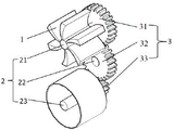
FIG. 1 is a schematic diagram of the transmission structure of the present invention.
Fig. 2 is a mechanical structural view of a generator using the transmission structure of the present invention.
Detailed Description
The present invention will be described in further detail below with reference to specific embodiments and with reference to the attached drawings.
As shown in fig. 1 and 2, the device includes an impeller 1, a shaft 2, a gear set 3, a baffle 4, a protective shell 5, and a stator coil 6.
The impeller 1 is arranged on the central shaft 21 in a matching way, the right end of the central shaft 21 is connected with the gear 31, one part of the impeller 1 is positioned outside the baffle plate 4, and the other part is positioned inside the baffle plate 4. The water flow impacts the blades which are not covered by the baffle 4, so that the impeller 1 rotates around the central shaft 21 and drives the central shaft 2 to rotate together. In this embodiment, half of the impeller 1 is outside the baffle 4 and the other half is inside the baffle 4. In general, the part of the impeller 1 outside the baffle 4 should not be smaller than the part inside the baffle 4, so that on one hand, the strength of water impact is ensured, the impeller 1 has enough power, and on the other hand, the installation and the later maintenance are also convenient.
The gear set 3 includes a first gear 31, a second gear 32 and a third gear 33, all of which are mounted in a gear guard 51. The shaft system 2 includes a first shaft 21, a second shaft 22 and a third shaft 23, wherein the rightmost end of the first shaft 21 is installed on the upper portion of the gear casing 51, and the left end and the impeller 1, the right end and the gear 31 are fixedly installed together. The rightmost end of the second shaft 22 is mounted on the middle portion of the gear guard 51, and the first shaft 21 and the second shaft 22 are connected by a gear 31 and a gear 32. The rightmost end of the third shaft 23 is arranged at the lower part of the gear protection shell 51, the left end is fixedly connected with the magnet protection shell 52, the right end is fixedly connected with the gear 33, and the second shaft 22 is connected with the third shaft 23 through the gear 32 and the gear 33. The shafts 21 and 23 are in dynamic sealing relationship with the gear guard 51, and the shaft 22 is directly fixed to the gear guard 51.
The baffle 4 is a semi-cylindrical structure, one end of the baffle is fixed on the gear protection shell 51, and the other end of the baffle is opened to be as high as the impeller 1, so that the baffle just covers half of the impeller 1.
The protective case 5 includes a gear protective case 51, a magnet protective case 52, and a motor protective case 53. The gear guard 51 is provided for mounting the gear set 3 and is designed for a sealing structure. The magnet shield 52 has a rotor magnet mounted inside thereof, and the motor shield 53 is located inside the rotor magnet and is fixed to the shaft by vertical screws so as not to rotate with the rotation of the impeller 1 and the rotation of the magnet shield 52 and the rotor magnet.
The stator coil 6 is fixedly arranged in the motor protective shell 53, and the sealing structure is designed to be always in a relatively static state and not to rotate along with the rotation of the impeller 1, the rotation of the magnet protective shell 52 and the rotation of the rotor magnet.
The water flow impacts the impeller 1, the impeller 1 rotates around the central shaft 21 and drives the central shaft 21 to rotate together, so as to drive the gear 31 to rotate synchronously, and the gear 31 can drive the gear 32 to rotate, so as to drive the gear 33 and the magnet protective shell 52 to rotate around the central shaft 23. When the magnet housing 52 having the magnet mounted thereon rotates around the center axis 23, the stator coil 6 fixed in the motor housing 53 generates power.
When the generator is installed, a single generator is assembled, then six generators are fixed on the sleeve, the coil 6 is sealed in the motor protective shell 53, and the motor protective shell 53 is placed in the magnet and is installed and fixed at the corresponding position of the sleeve. Finally, the sleeve is fixed in the well, and a central channel is arranged in the middle of the sleeve for the instrument to go into the well. Water in the well impacts one side of the impeller through the drainage of the sleeve, so that the impeller rotates, the torque is transmitted through the gear to drive the rotor magnet to rotate, and the six generators run simultaneously to complete power generation.
The foregoing is only a partial description of the preferred embodiments of the present invention. Any person skilled in the art may modify the above-described embodiments or modify them to equivalent solutions. Therefore, any simple modifications or equivalent substitutions made in accordance with the embodiments of the present invention are within the scope of the claims of the present invention.
Claims (7)
1. A gear drive for water injection well generator which characterized in that: including impeller, baffle, gear train, gear protective case, motor protective case, rotor magnet and stator solenoid, the impeller with the baffle is fixed outside the gear protective case, the baffle surrounds the part the impeller, gear train seal installation in the gear protective case, it is fixed through the center pin, the motor protective case does outward rotor magnet, interior doing the stator solenoid.
2. The gear assembly for a water injection well generator of claim 1, wherein: the impeller comprises a central shaft and blades uniformly distributed along the circumference of the central shaft.
3. The gear assembly for a water injection well generator of claim 2, wherein: the impeller is connected with the gear through the central shaft.
4. The gear assembly for a water injection well generator of claim 1, wherein: the motor protective shell is fixedly arranged on the underground sleeve through screws.
5. The gear assembly for a water injection well generator of claim 4, wherein: the number of the screws is two.
6. The gear assembly for a water injection well generator of claim 1, wherein: the stator coil is sealed in the motor protective shell.
7. The gear assembly for a water injection well generator of claim 1, wherein: the baffle surrounds half of the impeller.
Priority Applications (1)
| Application Number | Priority Date | Filing Date | Title |
|---|---|---|---|
| CN202010874357.8A CN114123647A (en) | 2020-08-26 | 2020-08-26 | Transmission device for water injection well generator |
Applications Claiming Priority (1)
| Application Number | Priority Date | Filing Date | Title |
|---|---|---|---|
| CN202010874357.8A CN114123647A (en) | 2020-08-26 | 2020-08-26 | Transmission device for water injection well generator |
Publications (1)
| Publication Number | Publication Date |
|---|---|
| CN114123647A true CN114123647A (en) | 2022-03-01 |
Family
ID=80374353
Family Applications (1)
| Application Number | Title | Priority Date | Filing Date |
|---|---|---|---|
| CN202010874357.8A Pending CN114123647A (en) | 2020-08-26 | 2020-08-26 | Transmission device for water injection well generator |
Country Status (1)
| Country | Link |
|---|---|
| CN (1) | CN114123647A (en) |
Cited By (1)
| Publication number | Priority date | Publication date | Assignee | Title |
|---|---|---|---|---|
| CN116735816A (en) * | 2023-05-08 | 2023-09-12 | 安徽中科天立泰技术有限公司 | A drainage network circulation water quality monitoring device |
Citations (6)
| Publication number | Priority date | Publication date | Assignee | Title |
|---|---|---|---|---|
| JPH05211741A (en) * | 1992-01-29 | 1993-08-20 | Nippon Steel Corp | Dc brushless motor pump |
| JP2005061392A (en) * | 2003-08-09 | 2005-03-10 | Ryozo Ota | Wind and water turbine with variable blade |
| JP2007064103A (en) * | 2005-08-31 | 2007-03-15 | Hitachi Ltd | Axial water turbine |
| US20080258473A1 (en) * | 2007-01-30 | 2008-10-23 | Mcmaster Thomas | Hybrid wind turbine system, apparatus and method |
| CN104675616A (en) * | 2013-11-29 | 2015-06-03 | 福州耕耘专利开发有限公司 | Tidal flow vortex impeller generator |
| CN212677024U (en) * | 2020-08-26 | 2021-03-09 | 中国石油化工股份有限公司 | Transmission device for generator of water injection well |
-
2020
- 2020-08-26 CN CN202010874357.8A patent/CN114123647A/en active Pending
Patent Citations (6)
| Publication number | Priority date | Publication date | Assignee | Title |
|---|---|---|---|---|
| JPH05211741A (en) * | 1992-01-29 | 1993-08-20 | Nippon Steel Corp | Dc brushless motor pump |
| JP2005061392A (en) * | 2003-08-09 | 2005-03-10 | Ryozo Ota | Wind and water turbine with variable blade |
| JP2007064103A (en) * | 2005-08-31 | 2007-03-15 | Hitachi Ltd | Axial water turbine |
| US20080258473A1 (en) * | 2007-01-30 | 2008-10-23 | Mcmaster Thomas | Hybrid wind turbine system, apparatus and method |
| CN104675616A (en) * | 2013-11-29 | 2015-06-03 | 福州耕耘专利开发有限公司 | Tidal flow vortex impeller generator |
| CN212677024U (en) * | 2020-08-26 | 2021-03-09 | 中国石油化工股份有限公司 | Transmission device for generator of water injection well |
Cited By (1)
| Publication number | Priority date | Publication date | Assignee | Title |
|---|---|---|---|---|
| CN116735816A (en) * | 2023-05-08 | 2023-09-12 | 安徽中科天立泰技术有限公司 | A drainage network circulation water quality monitoring device |
Similar Documents
| Publication | Publication Date | Title |
|---|---|---|
| US11391132B2 (en) | Turbine powered electrical submersible pump system | |
| US7451835B1 (en) | Downhole turbine | |
| CN102953912B (en) | Rotating magnetic field type underground generating set | |
| US20050012340A1 (en) | Downhole electrical submersible power generator | |
| US20220065081A1 (en) | Submersible canned motor pump | |
| CN212677024U (en) | Transmission device for generator of water injection well | |
| CN106351852A (en) | Vane wheel built-in submersible electric pump with stator coil protection sleeve | |
| RU2170348C1 (en) | A c generator to supply autonomous face geophysical and navigation complexes | |
| CN103470433B (en) | A kind of underground mud power generation device | |
| RU95107332A (en) | Turbogenerator of equipment for investigation of wells in process of drilling | |
| CN200993072Y (en) | Underground turbo generator | |
| CN201269096Y (en) | Down-hole electric generating apparatus | |
| CN108119293B (en) | Underground power generation device | |
| CN207485592U (en) | The embedded generator of underground rotary steering instrument | |
| CN113612348A (en) | Submersible screw pump based on ultra-low speed multi-rotor permanent magnet submersible motor | |
| CN206376976U (en) | an underground generator | |
| CN202220711U (en) | Rotating magnetic field type underground power generation device | |
| WO2013048007A2 (en) | High-efficiency tidal current generator, and hybrid generation system | |
| CN205209541U (en) | Non - excavation sensing device and drilling rod | |
| CN211287957U (en) | Underground high-power turbine generator | |
| CN113356810B (en) | A downhole power generation device for water injection well | |
| CN113719243B (en) | Power generation drill rod section and drilling tool | |
| CN101982654B (en) | Petroleum drilling mud generating system | |
| CN114056530A (en) | Energy-saving power generation equipment for ship | |
| CN201843725U (en) | Petroleum drilling mud power generation system |
Legal Events
| Date | Code | Title | Description |
|---|---|---|---|
| PB01 | Publication | ||
| PB01 | Publication | ||
| SE01 | Entry into force of request for substantive examination | ||
| SE01 | Entry into force of request for substantive examination | ||
| RJ01 | Rejection of invention patent application after publication |
Application publication date: 20220301 |
|
| RJ01 | Rejection of invention patent application after publication |