CN114123724A - Control method of switching power supply system and switching power supply system - Google Patents
Control method of switching power supply system and switching power supply system Download PDFInfo
- Publication number
- CN114123724A CN114123724A CN202210083909.2A CN202210083909A CN114123724A CN 114123724 A CN114123724 A CN 114123724A CN 202210083909 A CN202210083909 A CN 202210083909A CN 114123724 A CN114123724 A CN 114123724A
- Authority
- CN
- China
- Prior art keywords
- power supply
- current data
- switching power
- output current
- actual output
- Prior art date
- Legal status (The legal status is an assumption and is not a legal conclusion. Google has not performed a legal analysis and makes no representation as to the accuracy of the status listed.)
- Granted
Links
- 238000000034 method Methods 0.000 title claims description 44
- 230000002159 abnormal effect Effects 0.000 claims description 25
- 230000006870 function Effects 0.000 description 8
- 230000008569 process Effects 0.000 description 6
- 238000010586 diagram Methods 0.000 description 4
- 238000004590 computer program Methods 0.000 description 3
- 230000008859 change Effects 0.000 description 2
- 238000006243 chemical reaction Methods 0.000 description 2
- 230000003287 optical effect Effects 0.000 description 2
- 230000005856 abnormality Effects 0.000 description 1
- 230000008878 coupling Effects 0.000 description 1
- 238000010168 coupling process Methods 0.000 description 1
- 238000005859 coupling reaction Methods 0.000 description 1
- 230000003993 interaction Effects 0.000 description 1
- 230000004048 modification Effects 0.000 description 1
- 238000012986 modification Methods 0.000 description 1
- 230000010355 oscillation Effects 0.000 description 1
- 230000035484 reaction time Effects 0.000 description 1
- 230000008439 repair process Effects 0.000 description 1
- 238000006467 substitution reaction Methods 0.000 description 1
Images


Classifications
-
- H—ELECTRICITY
- H02—GENERATION; CONVERSION OR DISTRIBUTION OF ELECTRIC POWER
- H02M—APPARATUS FOR CONVERSION BETWEEN AC AND AC, BETWEEN AC AND DC, OR BETWEEN DC AND DC, AND FOR USE WITH MAINS OR SIMILAR POWER SUPPLY SYSTEMS; CONVERSION OF DC OR AC INPUT POWER INTO SURGE OUTPUT POWER; CONTROL OR REGULATION THEREOF
- H02M1/00—Details of apparatus for conversion
-
- H—ELECTRICITY
- H02—GENERATION; CONVERSION OR DISTRIBUTION OF ELECTRIC POWER
- H02H—EMERGENCY PROTECTIVE CIRCUIT ARRANGEMENTS
- H02H7/00—Emergency protective circuit arrangements specially adapted for specific types of electric machines or apparatus or for sectionalised protection of cable or line systems, and effecting automatic switching in the event of an undesired change from normal working conditions
- H02H7/10—Emergency protective circuit arrangements specially adapted for specific types of electric machines or apparatus or for sectionalised protection of cable or line systems, and effecting automatic switching in the event of an undesired change from normal working conditions for converters; for rectifiers
- H02H7/12—Emergency protective circuit arrangements specially adapted for specific types of electric machines or apparatus or for sectionalised protection of cable or line systems, and effecting automatic switching in the event of an undesired change from normal working conditions for converters; for rectifiers for static converters or rectifiers
- H02H7/1203—Circuits independent of the type of conversion
- H02H7/1206—Circuits independent of the type of conversion specially adapted to conversion cells composed of a plurality of parallel or serial connected elements
Landscapes
- Engineering & Computer Science (AREA)
- Power Engineering (AREA)
- Dc-Dc Converters (AREA)
- Direct Current Feeding And Distribution (AREA)
Abstract
A first switch power supply determines actual output current data of the first switch power supply according to configured total current data and actual output current data fed back by a second switch power supply, judges whether the actual output current data of the first switch power supply is larger than or equal to second preset current data, and closes the first switch power supply and the second switch power supply if the actual output current data of the first switch power supply is larger than or equal to the second preset current data.
Description
Technical Field
The invention relates to the technical field of switching power supplies, in particular to a control method of a switching power supply system and the switching power supply system.
Background
A switching power supply is a high-frequency power conversion device, and is one of power supplies. Because the current in the output power of a single switching power supply is influenced by the rated value of the single switching power supply, the current cannot change greatly, and in the industrial neighborhood, different currents output by the switching power supply have certain requirements according to different practical situations.
At present, the output of different currents is generally realized by connecting a plurality of switching power supplies in parallel, however, after the switching power supplies are connected in parallel, when an external control line between the switching power supplies is disconnected in the using process, the parallel slave switching power supply (slave) which is disconnected from the external control connection cannot output current, so that the parallel master switching power supply needs to output higher current to meet the total requirement due to compensation of the slave switching power supply, and the parallel master switching power supply is burnt out due to overlarge current output and no braking to close the output.
Disclosure of Invention
The invention mainly solves the technical problem of how to protect the abnormal and overlarge output current of the first switching power supply under the abnormal state that the second switching power supply cannot output current in the switching power supply system.
According to a first aspect, an embodiment provides a control method of a switching power supply system including a first switching power supply, one or more second switching power supplies, the first and second switching power supplies being connected in parallel by a control line;
the control method is applied to a first switching power supply and comprises the following steps:
receiving total current data and total voltage data of the switching power supply system input by a user;
determining configuration output current data of the second switching power supply according to the total current data, and sending the configuration output current data to the second switching power supply;
acquiring actual output current data fed back by a second switching power supply, and determining the actual output current data of the first switching power supply according to the actual output current data and the total current data of the second switching power supply;
judging whether the actual output current data of the first switching power supply is greater than or equal to second preset current data or not;
and if the actual output current data of the first switching power supply is greater than or equal to the second preset current data, closing the first switching power supply and the second switching power supply.
In an embodiment, after obtaining the actual output current data fed back by the second switching power supply, before determining the actual output current data of the first switching power supply and the output power data of the second switching power supply according to the actual output current data and the total current data of the second switching power supply, the method further includes:
judging whether the fed back actual output current data is smaller than first preset current data or not;
if the current data is smaller than the first preset current data, determining the actual output current data of the first switching power supply and the output power data of the second switching power supply according to the actual output current data and the total current data of the second switching power supply;
and if the current is larger than or equal to the first preset current data, continuously acquiring actual output current data fed back by the second switching power supply.
In an embodiment, if the first preset current data is greater than or equal to the first preset current data, the method further includes:
closing the timer and clearing the timing time of the timer;
the timing time of the timer is used for providing lag time for the second switching power supply; the lag time includes: the time required for sending the configured output current data to the second switching power supply, and the time required for the second switching power supply to adjust the actual output current data according to the received configured output current data.
In an embodiment, if the first preset current data is smaller than the first preset current data, the method further includes:
judging whether a timer is started or not, if not, starting the timer, continuously acquiring actual output current data fed back by a second switching power supply and judging whether the fed-back actual output current data is smaller than first preset current data or not;
if the timer is started, acquiring the timing time of the timer, and judging whether the timing time is greater than the preset time;
if the timing time is greater than or equal to the preset time, determining the actual output current data of the first switching power supply according to the actual output current data and the total current data of the second switching power supply;
and if the timing time is less than the preset time, continuously acquiring the actual output current data fed back by the second switching power supply and judging whether the fed back actual output current data is less than the first preset current data.
In an embodiment, if the actual output current data of the first switching power supply is greater than or equal to the second preset current data, the method further includes:
determining output power data of the second switching power supply according to the actual output current data and the total voltage data of the second switching power supply;
judging whether the output power data of the second switching power supply is larger than preset power data or not;
if the power is larger than the preset power data, displaying first reminding information to a user; the first reminding information is used for reminding a user that the switching power supply system is in an abnormal state in an initial loading state; otherwise, displaying the second reminding information to the user; the second reminding information is used for reminding a user that the switching power supply system is in an abnormal control line connection state.
According to a second aspect, an embodiment provides a control method of a switching power supply system, the switching power supply system including a switching power supply including a first power supply module, one or more second power supply modules, the first and second power supply modules being connected in parallel by a control line;
the control method is applied to a first power supply module and comprises the following steps:
receiving total current data and total voltage data of the switching power supply system input by a user;
determining configuration output current data of the second power supply module according to the total current data, and sending the configuration output current data to the second power supply module;
acquiring actual output current data fed back by a second power supply module, and determining the actual output current data of the first power supply module according to the actual output current data and the total current data of the second power supply module;
judging whether the actual output current data of the first power supply module is greater than or equal to second preset current data or not;
and if the actual output current data of the first power supply module is greater than or equal to the second preset current data, closing the first power supply module and the second power supply module.
In an embodiment, if the actual output current data of the first power module is greater than or equal to the second predetermined current data, the method further includes:
determining output power data of the second power supply module according to the actual output current data and the total voltage data of the second power supply module;
judging whether the output power data of the second power supply module is larger than preset power data or not;
if the power is larger than the preset power data, displaying first reminding information to a user; the first reminding information is used for reminding a user that the switching power supply system is in an abnormal state in an initial loading state; otherwise, displaying the second reminding information to the user; the second reminding information is used for reminding a user that the switching power supply system is in an abnormal control line connection state.
According to a third aspect, there is provided in one embodiment a switching power supply system comprising: the power supply comprises a first switching power supply and one or more second switching power supplies, wherein the first switching power supply and the second switching power supplies are connected in parallel through a control line;
the first switching power supply is used for receiving total current data and total voltage data of the switching power supply system input by a user; determining configuration output current data of the second switching power supply according to the total current data, and sending the configuration output current data to the second switching power supply; acquiring actual output current data fed back by a second switching power supply, and determining the actual output current data of the first switching power supply according to the actual output current data and the total current data of the second switching power supply; judging whether the actual output current data of the first switching power supply is greater than or equal to second preset current data or not; if the actual output current data of the first switching power supply is larger than or equal to the second preset current data, the first switching power supply and the second switching power supply are turned off;
the second switching power supply is used for receiving configuration output current data sent by the first switching power supply; and outputting current according to the configuration output current data.
According to a fourth aspect, an embodiment provides a switching power supply system, including a switching power supply, the switching power supply including a first power supply module, one or more second power supply modules, the first and second power supply modules being connected in parallel by a control line;
the first power supply module is used for receiving total current data and total voltage data of the switching power supply system input by a user; determining configuration output current data of the second power supply module according to the total current data, and sending the configuration output current data to the second power supply module; acquiring actual output current data fed back by a second power supply module, and determining the actual output current data of the first power supply module according to the actual output current data and the total current data of the second power supply module; judging whether the actual output current data of the first power supply module is greater than or equal to second preset current data or not; if the actual output current data of the first power supply module is larger than or equal to second preset current data, closing the first power supply module and the second power supply module;
the second power supply module is used for receiving the configuration output current data sent by the first power supply module; and outputting current according to the configuration output current data.
According to a fifth aspect, an embodiment provides a computer readable storage medium having a program stored thereon, the program being executable by a processor to implement the method as described in the above embodiments.
According to the control method of the switching power supply system/the switching power supply system of the embodiment, the first switching power supply determines the actual output current data of the first switching power supply according to the configured total current data and the actual output current data fed back by the second switching power supply, judges whether the actual output current data of the first switching power supply is greater than or equal to the second preset current data, and turns off the first switching power supply and the second switching power supply if the actual output current data of the first switching power supply is greater than or equal to the second preset current data.
Drawings
Fig. 1 is a schematic structural diagram of a switching power supply system according to an embodiment;
fig. 2 is a flowchart of a control method of the switching power supply system according to an embodiment;
FIG. 3 is a detailed flowchart of the control method shown in FIG. 2;
fig. 4 is a schematic structural diagram of a switching power supply system according to another embodiment;
fig. 5 is a flowchart of a control method of a switching power supply system according to another embodiment.
Detailed Description
The present invention will be described in further detail with reference to the following detailed description and accompanying drawings. Wherein like elements in different embodiments are numbered with like associated elements. In the following description, numerous details are set forth in order to provide a better understanding of the present application. However, those skilled in the art will readily recognize that some of the features may be omitted or replaced with other elements, materials, methods in different instances. In some instances, certain operations related to the present application have not been shown or described in detail in order to avoid obscuring the core of the present application from excessive description, and it is not necessary for those skilled in the art to describe these operations in detail, so that they may be fully understood from the description in the specification and the general knowledge in the art.
Furthermore, the features, operations, or characteristics described in the specification may be combined in any suitable manner to form various embodiments. Also, the various steps or actions in the method descriptions may be transposed or transposed in order, as will be apparent to one of ordinary skill in the art. Thus, the various sequences in the specification and drawings are for the purpose of describing certain embodiments only and are not intended to imply a required sequence unless otherwise indicated where such sequence must be followed.
The numbering of the components as such, e.g., "first", "second", etc., is used herein only to distinguish the objects as described, and does not have any sequential or technical meaning. The term "connected" and "coupled" when used in this application, unless otherwise indicated, includes both direct and indirect connections (couplings).
The first embodiment is as follows:
referring to fig. 1, fig. 1 is a schematic structural diagram of a switching power supply system according to an embodiment of the present invention, the switching power supply system includes a first switching power supply a10, one or more second switching power supplies a20, and the first switching power supply a10 and the second switching power supply a20 are connected in parallel through a control line.
In this embodiment, the first switching power supply a10 is a master switching power supply, and the second switching power supply a20 is a slave switching power supply, and in a single switching power supply system, there may be one first switching power supply a10 and one second switching power supply a20, or two or more. The external input interfaces of the first switching power supply a10 and the second switching power supply a20 are connected such that the first switching power supply a10 may control the output voltage or the output current of the second switching power supply through a control line; meanwhile, the second switching power supply a20 feeds back its actual output current value or actual output voltage value to the first switching power supply a10 by controlling a feedback line, and the first switching power supply a10 performs actual compensation by the fed back actual output current value or actual output voltage value, so that the total current output by the switching power supply system reaches the current value set by the user.
The operation principle of the switching power supply system of the parallel configuration is explained below by two examples.
For example: when the first switching power supply a10 controls the two second switching power supplies a20 to output 80V/30A, the first switching power supply a10 generally controls the two second switching power supplies a20 to output signals of voltage 80V/current 10A through an external control line of a rear terminal, theoretically, the output current of the first switching power supply a10 plus the two second switching power supplies a20 is 30A at this time, but because of the influence of circuit elements and the like, the actual output of the second switching power supply a20 floats (the actual output current is smaller than 10A), and at this time, the first switching power supply a10 compensates the total output current according to the actual output current value fed back by the second switching power supply a20, that is, the actual output current of the first switching power supply a10 is increased, so that the total output current reaches 30A.
However, in the actual use process, the external control line of the rear terminal of the first switching power supply a10 or the second switching power supply a20 may be connected in a virtual manner, or the control line may be loosened during the moving process of the device. In this case, the first switching power supply a10 fails to control the output of the second switching power supply a20, so that the second switching power supply a20 has no output, and in this case, the first switching power supply a10 needs to perform current compensation, which results in an excessive output current of the first switching power supply a 10.
For another example: the rated output maximum current of the first switching power supply A10 is 30A, and if the first switching power supply A10 controls two second switching power supplies A20 at the moment, the output maximum total current is 90A; if the total current set by the user is 60A, the theoretical output current of each of the first switching power supply a10 and the two second switching power supplies a20 is 20A, but if the external control line is loosened, no output of the two second switching power supplies a20 occurs, the first switching power supply a10 needs to compensate to 60A, and the hardware protection current of the first switching power supply is completely exceeded, so that the first switching power supply is burnt out.
Based on the above analysis, referring to fig. 2, an embodiment of the present invention further provides a control method of a switching power supply system, which is hereinafter referred to as a control method for short, where the first switching power supply a10 has a controller capable of controlling outputs of the first switching power supply a10 and each of the second switching power supplies a20, and the control method is applied to the controller of the first switching power supply a10, and is capable of turning off the first switching power supply a10 and the second switching power supply a20 when detecting that an output current of the first switching power supply a10 exceeds second preset current data, so as to protect the first switching power supply a10 and the second switching power supply a 20. The control method provided by the present embodiment includes steps a100 to a500, which are described in detail below.
Step A100: the first switching power supply a10 receives user input of total current data and total voltage data of the switching power supply system. The first switching power supply a10 of this embodiment may be provided with a human-computer interaction module, such as a touch screen, a button, etc., through which a user may input total current data and total voltage data.
Step A200: the first switching power supply A10 determines the configuration output current data of the second switching power supply A20 according to the total current data, and transmits the configuration output current data to the second switching power supply. The configuration output current data in this embodiment is the current value of the theoretical output current of the second switching power supply a20, and if the number of the second switching power supplies a20 is N, the configuration output current data of each second switching power supply a20 is Iset/(N +1), Iset representing the total current data. In addition, the configured output current data of the first switching power supply a10 is also Iset/(N +1), that is, the current values of the theoretical output currents of the first switching power supply a10 and the second switching power supply a20 are the same.
Step A300: the first switching power supply A10 acquires actual output current data fed back by the second switching power supply A20, and determines the actual output current data of the first switching power supply according to the actual output current data and the total current data of the second switching power supply. The actual output current data of the second switching power supply a20 in this embodiment is the current value of the actual output current. Due to the influence of the elements in the circuit, the actual output current data of the second switching power supply a20 has a certain difference from the configuration current data, generally speaking, the actual output current data of the second switching power supply a20 is smaller than the configuration current data, so that the current actually output by the second switching power supply a20 is smaller than the current it needs to output, the first switching power supply a10 needs to compensate for the missing current, and therefore, the first switching power supply a10 needs to output a larger current than the configuration current data. In summary, the present embodiment determines the actual output current data of the first switching power supply according to the total current data and the actual output current data of the second switching power supply a 20.
Step A400: it is determined whether the actual output current data of the first switching power supply a10 is equal to or greater than the second preset current data.
In some abnormal situations, for example: the external input interface connecting wire of the second switching power supply A20 is loose or virtual; for another example: the user can continuously and rapidly switch on and off the switching power supply system, which in extreme cases may cause the first switching power supply a10 and the second switching power supply a20 of the entire switching power supply system to be in an oscillating state. In the abnormal state, the actual output current data of the first switching power supply a10 is increased in a large range, and in order to avoid the first switching power supply a10 from being burnt out due to an excessive output current, it is necessary to determine whether the actual output current data of the first switching power supply a10 is greater than or equal to the maximum current data that can be borne by the first switching power supply a10, and the maximum current data that can be borne by the first switching power supply a10 is the second preset current data.
Step A500: if the actual output current data of the first switching power supply A10 is greater than or equal to the second preset current data, the first switching power supply A10 and the second switching power supply A20 are turned off.
If the judgment result is that: when the actual output current data of the first switching power supply a10 is greater than or equal to the second preset current data, it indicates that the actual output current data of the first switching power supply a10 exceeds the maximum current data that can be borne by the first switching power supply a10, and at this time, the entire switching power supply system is in an abnormal state, and the outputs of the first switching power supply a10 and the second switching power supply a20 need to be turned off, so as to protect the switching power supply system.
If the judgment result is that: the actual output current data of the first switching power supply a10 is smaller than the second preset current data, which indicates that the actual output current data of the first switching power supply a10 does not exceed the maximum current data that can be borne by the first switching power supply a10, and belongs to the normal operating state thereof, and at this time, the outputs of the first switching power supply a10 and the second switching power supply a20 are continuously maintained.
In an embodiment, after acquiring the actual output current data fed back by the second switching power supply a20 in step a300, before determining the actual output current data of the first switching power supply and the output power data of the second switching power supply according to the actual output current data of the second switching power supply and the total current data, the method further includes:
it is determined whether the actual output current data fed back by the second switching power supply a20 is less than the first preset current data.
If the actual output current data fed back by the second switching power supply A20 is smaller than the first preset current data, judging whether to start a timer, if not, starting the timer, continuously acquiring the actual output current data fed back by the second switching power supply and judging whether the fed-back actual output current data is smaller than the first preset current data; if the timer is started, acquiring the timing time of the timer, and judging whether the timing time is greater than the preset time; if the timing time is greater than or equal to the preset time, the actual output current data of the first switching power supply A10 and the output power data of the second switching power supply A20 are determined according to the actual output current data and the total current data of the second switching power supply A20. If the timing time is less than the preset time, continuously acquiring the actual output current data fed back by the second switching power supply A20 and judging whether the fed back actual output current data is less than the first preset current data. The timing time of the timer is used for providing lag time for the second switching power supply; since in practical implementation, because of the mechanical time of the actual switching reaction of the circuit components, etc., when the first switching power supply a10 sends the configuration output current data to the second switching power supply a20 through the control line, and then the second switching power supply a20 receives the configuration output current data, there is a certain lag time until the second switching power supply a20 reacts to the actual current output, so the lag time includes: the time required to send the configuration output current data to the second switching power supply, and the time required for the second switching power supply a20 to adjust the actual output current data according to the received configuration output current data. In the embodiment, the timer is arranged to time the lag time, so that the misjudgment caused by the change caused by the large-amplitude adjustment of the configuration output current data at the moment of load starting or in the running process of the switching power supply system is eliminated.
If the actual output current data fed back by the second switching power supply A20 is greater than or equal to the first preset current data, if the timer is started at the moment, the timer is closed, the timing time of the timer is cleared, and the actual output current data fed back by the second switching power supply is continuously acquired.
In this embodiment, the first preset current data is 20% of the configured output current data of the second switching power supply a20, the preset time is obtained by integrating the mechanical time realized by switching the components used by the second switching power supply a20 and the maximum time of the second switching power supply a20 circuit for bearing the extra-large current, and different hardware circuit designs are adopted.
In an embodiment, in step a500, if the actual output current data of the first switching power supply a10 is greater than or equal to the second preset current data, the method further includes:
the output power data of the second switching power supply is determined based on the actual output current data of the second switching power supply a20 and the total voltage data.
It is determined whether the output power data of the second switching power supply a20 is greater than the preset power data.
If the power is larger than the preset power data, displaying first reminding information to a user; the first reminding information is used for reminding a user that the switching power supply system is in an abnormal state of an initial loading state; otherwise, displaying the second reminding information to the user; the second reminding information is used for reminding a user that the switching power supply system is in an abnormal control line connection state.
When the actual output current data of the first switching power supply a10 is greater than or equal to the second preset current data, there may be two reasons for this abnormal state, one is that the user performs continuous and rapid on-off operation on the switching power supply system, and in extreme cases, the first switching power supply a10 and the second switching power supply a20 of the entire switching power supply system are in an oscillating state; the other is that the external input interface connection wire of the second switching power supply a20 is loose or virtual, which results in an abnormal state that the second switching power supply a20 has no output current.
Therefore, in the abnormal state, the first switching power supply a10 and the second switching power supply a20 are turned off, and the user is prompted with information of the cause of the abnormal state according to different causes. Therefore, in the embodiment, the reason for the abnormal state is determined by determining whether the output power of the second switching power supply a20 is greater than the preset power data, and if the output power data of the second switching power supply a20 is greater than the preset power data, a first reminding message is displayed to the user, that is, the first switching power supply a10 and the second switching power supply a20 are in an abnormal state caused by the oscillation state; if the output power data of the second switching power supply a20 is less than or equal to the preset power data, a second reminding message is displayed to the user, that is, an abnormality caused by the loose or virtual connection of the external input interface connection line of the second switching power supply a 20.
In this embodiment, the output Power data Power = Vset × CURR of the second switching Power supply a20, where Vset is total voltage data input by the user, because the first switching Power supply a10 and the one or more second switching Power supplies a20 are connected in parallel, the output voltages of the second switching Power supply a20 and the first switching Power supply a10 are the same, the output voltages are all equal to the total voltage data, and CURR is actual output current data of the second switching Power supply a20, that is, the current value of the output current of the second switching Power supply a 20.
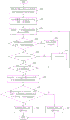
To sum up, referring to fig. 3, the control flow of the switching power supply system provided by the embodiment of the invention is as follows:
step 101: and receiving total current data and total voltage data of the switching power supply system input by a user.
Step 102: and determining configuration output current data of the second switching power supply according to the total current data, and sending the configuration output current data to the second switching power supply.
Step 103: and acquiring actual output current data fed back by the second switching power supply.
Step 104: and judging whether the actual output current data fed back by the second switching power supply is smaller than the first preset current data.
Step 105: if the current is greater than or equal to the first preset current data, the timer is closed, the timing time of the timer is cleared, and the step 103 is returned.
Step 106: if the current is smaller than the first preset current data, whether the timer is started or not is judged.
Step 107: if the timer is not started, the timer is started, and the process returns to step 103.
Step 108: if the timer is started, acquiring the timing time of the timer, and determining whether the timing time is greater than or equal to the preset time, if the timing time is less than the preset time, returning to step 103.
Step 109: and if the timing time is more than or equal to the preset time, determining the actual output current data of the first switching power supply and the output power data of the second switching power supply according to the actual output current data and the total current data of the second switching power supply.
Step 110: and judging whether the output power data of the second switching power supply is greater than or equal to the preset power data or not, and judging whether the actual output current data of the first switching power supply is greater than or equal to the second preset current data or not.
Step 111: and if the actual output current data of the first switching power supply is greater than or equal to the second preset current data and the output power data of the second switching power supply is greater than or equal to the preset power data, closing the first switching power supply and the second switching power supply and displaying the first reminding information to the user.
Step 112: otherwise, the first switching power supply and the second switching power supply are closed, and second reminding information is displayed for the user.
In the embodiment of the present invention, the first switching power supply a10 is used as a master switching power supply, the one or more second switching power supplies a20 are used as slave switching power supplies, and the first switching power supply a10 uses actual output current data fed back by the second switching power supply a20 as a judgment basis to judge whether the second switching power supply a20 has a current output failure condition caused by an abnormal state, so as to avoid the problem that the first switching power supply a10 is burned out due to an excessive output current; in addition, whether the time is counted to the preset time is judged by setting the timer, so that misjudgment caused by delay of mechanical reaction time of components in the switching power supply due to switching of the on-load and off-load states of a circuit or adjustment of set total current data (total voltage data) in the operation process is eliminated, and the stability of the switching power supply system is better ensured; and finally, when the output current of the second switching power supply in the switching power supply system is judged to belong to the abnormal state, the specific reason causing the abnormal state is determined by further judging the actual output power data of the second switching power supply, so that the user can conveniently repair the abnormal condition.
Example two:
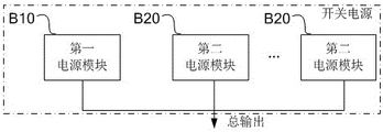
referring to fig. 4, fig. 4 is a schematic structural diagram of a switching power supply system according to another embodiment, where the switching power supply system includes a switching power supply, the switching power supply includes a first power module B10, one or more second power modules B20, and the first power module B10 and the second power module B20 are connected in parallel through a control line.
In this embodiment, the first power module B10 is a master power module, the second power module B20 is a slave power module, and in a switching power system, there are one first power module B10 and one second power module B20, or two or more second power modules. The external input interfaces of the first power module B10 and the second power module B20 are connected such that the first power module B10 can control the output voltage or the output current of the second switching power supply through the control line; meanwhile, the second power supply module B20 feeds back its actual output current value or actual output voltage value to the first power supply module B10 by controlling a feedback line, and the first power supply module B10 performs actual compensation by the fed back actual output current value or actual output voltage value, so that the total current output by the switching power supply system reaches the current value set by the user.
Referring to fig. 5, fig. 5 is a flowchart illustrating a control method of a switching power supply system according to another embodiment, where the control method provided in this embodiment includes steps B100 to B500, which are described in detail below.
And step B100, the first power supply module B10 receives total current data and total voltage data of the switching power supply system input by a user.
Step B200: based on the total current data, the first power module B10 determines configuration output current data for the second power module B20 and sends the configuration output current data to the second power module B20.
Step B300: the first power module B10 obtains the actual output current data fed back by the second power module, and determines the actual output current data of the first power module according to the actual output current data of the second power module and the total current data.
Step B400: it is determined whether the actual output current data of the first power module B10 is greater than or equal to the second predetermined current data.
Step B500: if the actual output current data of the first power module B10 is greater than or equal to the second predetermined current data, the first power module B10 and the second power module B20 are turned off.
It should be noted that the first power module B10 has the same functions as the first switching power supply a10 in the first embodiment, and the second power module B20 has the same functions as the second switching power supply a20 in the first embodiment. Since the specific implementation of the first switching power supply a10 and the second switching power supply a20 are described in detail in the first embodiment, the detailed description thereof is omitted here.
Those skilled in the art will appreciate that all or part of the functions of the various methods in the above embodiments may be implemented by hardware, or may be implemented by computer programs. When all or part of the functions of the above embodiments are implemented by a computer program, the program may be stored in a computer-readable storage medium, and the storage medium may include: a read only memory, a random access memory, a magnetic disk, an optical disk, a hard disk, etc., and the program is executed by a computer to realize the above functions. For example, the program may be stored in a memory of the device, and when the program in the memory is executed by the processor, all or part of the functions described above may be implemented. In addition, when all or part of the functions in the above embodiments are implemented by a computer program, the program may be stored in a storage medium such as a server, another computer, a magnetic disk, an optical disk, a flash disk, or a removable hard disk, and may be downloaded or copied to a memory of a local device, or may be version-updated in a system of the local device, and when the program in the memory is executed by a processor, all or part of the functions in the above embodiments may be implemented.
The present invention has been described in terms of specific examples, which are provided to aid understanding of the invention and are not intended to be limiting. For a person skilled in the art to which the invention pertains, several simple deductions, modifications or substitutions may be made according to the idea of the invention.
Claims (10)
1. The control method of the switching power supply system is characterized in that the switching power supply system comprises a first switching power supply and one or more second switching power supplies, wherein the first switching power supply and the second switching power supplies are connected in parallel through a control line;
the control method is applied to a first switching power supply and comprises the following steps:
receiving total current data and total voltage data of the switching power supply system input by a user;
determining configuration output current data of the second switching power supply according to the total current data, and sending the configuration output current data to the second switching power supply;
acquiring actual output current data fed back by a second switching power supply, and determining the actual output current data of the first switching power supply according to the actual output current data and the total current data of the second switching power supply;
judging whether the actual output current data of the first switching power supply is greater than or equal to second preset current data or not;
and if the actual output current data of the first switching power supply is greater than or equal to the second preset current data, closing the first switching power supply and the second switching power supply.
2. The control method of claim 1, wherein after obtaining the actual output current data fed back by the second switching power supply, before determining the actual output current data of the first switching power supply and the output power data of the second switching power supply according to the actual output current data of the second switching power supply and the total current data, further comprising:
judging whether the fed back actual output current data is smaller than first preset current data or not;
if the current data is smaller than the first preset current data, determining the actual output current data of the first switching power supply and the output power data of the second switching power supply according to the actual output current data and the total current data of the second switching power supply;
and if the current is larger than or equal to the first preset current data, continuously acquiring actual output current data fed back by the second switching power supply.
3. The control method according to claim 2, wherein if the first preset current data is greater than or equal to the first preset current data, further comprising:
closing the timer and clearing the timing time of the timer;
the timing time of the timer is used for providing lag time for the second switching power supply; the lag time includes: the time required for sending the configured output current data to the second switching power supply, and the time required for the second switching power supply to adjust the actual output current data according to the received configured output current data.
4. The control method of claim 2, wherein if the first preset current data is less than the first preset current data, further comprising:
judging whether a timer is started or not, if not, starting the timer, continuously acquiring actual output current data fed back by a second switching power supply and judging whether the fed-back actual output current data is smaller than first preset current data or not;
if the timer is started, acquiring the timing time of the timer, and judging whether the timing time is greater than the preset time;
if the timing time is greater than or equal to the preset time, determining the actual output current data of the first switching power supply according to the actual output current data and the total current data of the second switching power supply;
and if the timing time is less than the preset time, continuously acquiring the actual output current data fed back by the second switching power supply and judging whether the fed back actual output current data is less than the first preset current data.
5. The control method of claim 1, wherein if the actual output current data of the first switching power supply is greater than or equal to a second predetermined current data, further comprising:
determining output power data of the second switching power supply according to the actual output current data and the total voltage data of the second switching power supply;
judging whether the output power data of the second switching power supply is larger than preset power data or not;
if the power is larger than the preset power data, displaying first reminding information to a user; the first reminding information is used for reminding a user that the switching power supply system is in an abnormal state in an initial loading state; otherwise, displaying the second reminding information to the user; the second reminding information is used for reminding a user that the switching power supply system is in an abnormal control line connection state.
6. The control method of the switching power supply system is characterized in that the switching power supply system comprises a switching power supply, the switching power supply comprises a first power supply module and one or more second power supply modules, and the first power supply module and the second power supply modules are connected in parallel through a control line;
the control method is applied to a first power supply module and comprises the following steps:
receiving total current data and total voltage data of the switching power supply system input by a user;
determining configuration output current data of the second power supply module according to the total current data, and sending the configuration output current data to the second power supply module;
acquiring actual output current data fed back by a second power supply module, and determining the actual output current data of the first power supply module according to the actual output current data and the total current data of the second power supply module;
judging whether the actual output current data of the first power supply module is greater than or equal to second preset current data or not;
and if the actual output current data of the first power supply module is greater than or equal to the second preset current data, closing the first power supply module and the second power supply module.
7. The control method of claim 6, wherein if the actual output current data of the first power module is greater than or equal to the second predetermined current data, further comprising:
determining output power data of the second power supply module according to the actual output current data and the total voltage data of the second power supply module;
judging whether the output power data of the second power supply module is larger than preset power data or not;
if the power is larger than the preset power data, displaying first reminding information to a user; the first reminding information is used for reminding a user that the switching power supply system is in an abnormal state in an initial loading state; otherwise, displaying the second reminding information to the user; the second reminding information is used for reminding a user that the switching power supply system is in an abnormal control line connection state.
8. A switching power supply system, comprising: the power supply comprises a first switching power supply and one or more second switching power supplies, wherein the first switching power supply and the second switching power supplies are connected in parallel through a control line;
the first switching power supply is used for receiving total current data and total voltage data of the switching power supply system input by a user; determining configuration output current data of the second switching power supply according to the total current data, and sending the configuration output current data to the second switching power supply; acquiring actual output current data fed back by a second switching power supply, and determining the actual output current data of the first switching power supply according to the actual output current data and the total current data of the second switching power supply; judging whether the actual output current data of the first switching power supply is greater than or equal to second preset current data or not; if the actual output current data of the first switching power supply is larger than or equal to the second preset current data, the first switching power supply and the second switching power supply are turned off;
the second switching power supply is used for receiving configuration output current data sent by the first switching power supply; and outputting current according to the configuration output current data.
9. A switching power supply system is characterized by comprising a switching power supply, wherein the switching power supply comprises a first power supply module and one or more second power supply modules, and the first power supply module and the second power supply modules are connected in parallel through a control line;
the first power supply module is used for receiving total current data and total voltage data of the switching power supply system input by a user; determining configuration output current data of the second power supply module according to the total current data, and sending the configuration output current data to the second power supply module; acquiring actual output current data fed back by a second power supply module, and determining the actual output current data of the first power supply module according to the actual output current data and the total current data of the second power supply module; judging whether the actual output current data of the first power supply module is greater than or equal to second preset current data or not; if the actual output current data of the first power supply module is larger than or equal to second preset current data, closing the first power supply module and the second power supply module;
the second power supply module is used for receiving the configuration output current data sent by the first power supply module; and outputting current according to the configuration output current data.
10. A computer-readable storage medium, characterized in that the medium has stored thereon a program which is executable by a processor to implement the method according to any one of claims 1-7.
Priority Applications (1)
| Application Number | Priority Date | Filing Date | Title |
|---|---|---|---|
| CN202210083909.2A CN114123724B (en) | 2022-01-25 | 2022-01-25 | Control method of switching power supply system and switching power supply system |
Applications Claiming Priority (1)
| Application Number | Priority Date | Filing Date | Title |
|---|---|---|---|
| CN202210083909.2A CN114123724B (en) | 2022-01-25 | 2022-01-25 | Control method of switching power supply system and switching power supply system |
Publications (2)
| Publication Number | Publication Date |
|---|---|
| CN114123724A true CN114123724A (en) | 2022-03-01 |
| CN114123724B CN114123724B (en) | 2022-05-10 |
Family
ID=80360856
Family Applications (1)
| Application Number | Title | Priority Date | Filing Date |
|---|---|---|---|
| CN202210083909.2A Active CN114123724B (en) | 2022-01-25 | 2022-01-25 | Control method of switching power supply system and switching power supply system |
Country Status (1)
| Country | Link |
|---|---|
| CN (1) | CN114123724B (en) |
Cited By (2)
| Publication number | Priority date | Publication date | Assignee | Title |
|---|---|---|---|---|
| CN114928237A (en) * | 2022-06-07 | 2022-08-19 | 阳光电源股份有限公司 | Resonant switch capacitor converter and photovoltaic system |
| US12438454B2 (en) | 2022-10-12 | 2025-10-07 | Deco Lntegration Technology Co., Limited | Millimeter wave-based switching power supply |
Citations (6)
| Publication number | Priority date | Publication date | Assignee | Title |
|---|---|---|---|---|
| US5721490A (en) * | 1995-02-09 | 1998-02-24 | Hitachi Medical Corporation | Power source apparatus including a plurality of output current amplifiers connected in parallel and MRI apparatus using the same |
| JPH10225126A (en) * | 1997-02-12 | 1998-08-21 | Omron Corp | Power supply |
| CN103885372A (en) * | 2012-12-24 | 2014-06-25 | 中国移动通信集团河北有限公司 | Switch power supply rectifier module monitoring and early warning method and system |
| CN106129968A (en) * | 2016-07-12 | 2016-11-16 | 成都芯源系统有限公司 | Resonant converter and overcurrent protection circuit and overcurrent protection method thereof |
| CN110784095A (en) * | 2019-10-31 | 2020-02-11 | 深圳市奥拓电子股份有限公司 | High-efficiency switching power supply circuit and LED display screen |
| CN113659533A (en) * | 2021-09-10 | 2021-11-16 | 阳光电源股份有限公司 | Power converter parallel system and energy storage system |
-
2022
- 2022-01-25 CN CN202210083909.2A patent/CN114123724B/en active Active
Patent Citations (6)
| Publication number | Priority date | Publication date | Assignee | Title |
|---|---|---|---|---|
| US5721490A (en) * | 1995-02-09 | 1998-02-24 | Hitachi Medical Corporation | Power source apparatus including a plurality of output current amplifiers connected in parallel and MRI apparatus using the same |
| JPH10225126A (en) * | 1997-02-12 | 1998-08-21 | Omron Corp | Power supply |
| CN103885372A (en) * | 2012-12-24 | 2014-06-25 | 中国移动通信集团河北有限公司 | Switch power supply rectifier module monitoring and early warning method and system |
| CN106129968A (en) * | 2016-07-12 | 2016-11-16 | 成都芯源系统有限公司 | Resonant converter and overcurrent protection circuit and overcurrent protection method thereof |
| CN110784095A (en) * | 2019-10-31 | 2020-02-11 | 深圳市奥拓电子股份有限公司 | High-efficiency switching power supply circuit and LED display screen |
| CN113659533A (en) * | 2021-09-10 | 2021-11-16 | 阳光电源股份有限公司 | Power converter parallel system and energy storage system |
Cited By (2)
| Publication number | Priority date | Publication date | Assignee | Title |
|---|---|---|---|---|
| CN114928237A (en) * | 2022-06-07 | 2022-08-19 | 阳光电源股份有限公司 | Resonant switch capacitor converter and photovoltaic system |
| US12438454B2 (en) | 2022-10-12 | 2025-10-07 | Deco Lntegration Technology Co., Limited | Millimeter wave-based switching power supply |
Also Published As
| Publication number | Publication date |
|---|---|
| CN114123724B (en) | 2022-05-10 |
Similar Documents
| Publication | Publication Date | Title |
|---|---|---|
| CN114123724B (en) | Control method of switching power supply system and switching power supply system | |
| US9893561B2 (en) | Power supply conversion system and method of controlling the same | |
| US10727544B2 (en) | Uninterruptible power supply and battery activation operation method thereof | |
| CN112039313B (en) | Auxiliary power supply device, control method of auxiliary power supply device, and converter | |
| CN105098718A (en) | Power supply device and overvoltage protection method | |
| CN1513224A (en) | Power Architecture with Controlled Power-Up and Power-Down Sequencing | |
| TW201841459A (en) | Fast transient response circuit | |
| CN108270398A (en) | Control method is opened in photovoltaic system and cutoff device and its provisioning instruction response | |
| CN108270397B (en) | Turn-on control method of shut-off device and photovoltaic system | |
| JP2023183644A (en) | System power structure, backup power supply, control method, and control program | |
| JP2012226756A (en) | Adapter circuit for power supply | |
| JPWO2015159785A1 (en) | Power system | |
| CN113746060B (en) | Protection device for hot plug of laser device | |
| JP6671979B2 (en) | Power supply switching device | |
| JP2024083983A (en) | Power System | |
| CN221573844U (en) | Trigger circuit for release and circuit breaker | |
| KR102747852B1 (en) | Active inrush current limiter of high voltage distribution system and method of using the same | |
| CN117294132B (en) | Power supply circuit and switching method thereof | |
| CN115864349B (en) | Protection circuits and power supply equipment for power-limiting power supplies | |
| US10367371B2 (en) | Intelligent charging system and intelligent charging method | |
| EP4492627A1 (en) | Power supply system and control method | |
| TWI891353B (en) | Power supply system and control method | |
| US11561594B2 (en) | Electronic device and method of power supply protection for connection port | |
| CN223843532U (en) | Solid state circuit breaker | |
| CN113013834B (en) | Distributed power supply circuit power-off pre-protection circuit and method |
Legal Events
| Date | Code | Title | Description |
|---|---|---|---|
| PB01 | Publication | ||
| PB01 | Publication | ||
| SE01 | Entry into force of request for substantive examination | ||
| SE01 | Entry into force of request for substantive examination | ||
| GR01 | Patent grant | ||
| GR01 | Patent grant |