Disclosure of Invention
The purpose of the invention is as follows: in order to overcome the defects in the prior art, the invention provides a high-power supply control system and method of a mixed signal testing machine.
The technical scheme is as follows: in order to achieve the purpose, the invention adopts the technical scheme that:
a high-power supply control method of a mixed signal testing machine comprises the following steps:
step 1, dividing a main power supply into a control power supply pack and a function board power supply pack, wherein the function board power supply pack comprises more than two function board power supply modules. The control power supply set is monitored by an upper computer in real time. And the power supply set of the functional board card is controlled and monitored by an upper computer in real time.
And 2, selecting the power supply modules of the functional board cards to be connected in parallel according to the loads of the functional board cards.
And 3, outputting the power modules of the parallel functional board cards through primary power filtering and primary power convergence.
And 4, outputting the power after the primary confluence output through secondary power filtering and secondary power confluence.
And 5, delivering the power output by the secondary power supply to the functional board card corresponding to the load.
Preferably: the primary power supply confluence output and the secondary power supply confluence output are connected and output by adopting a confluence bar.
Preferably: and the main power supply is converted into different power supplies actually required by the functional board card in a grading manner through the DC/DC module.
A high-power control system of a mixed signal testing machine comprises a main power supply, a power supply subsystem and a power supply output bus subsystem, wherein:
the main power supply is divided into a control power supply set and a function board card power supply set, and the control power supply set is monitored by an upper computer in real time. And the power supply set of the functional board card is controlled and monitored by an upper computer in real time. The functional board power supply pack comprises more than two functional board power modules.
The power supply subsystem comprises a PCB A board, the PCB A board comprises a first-level power supply filter circuit and a first-level power supply convergence output circuit, the functional board card power supply modules are connected in parallel and then connected with the first-level power supply filter circuit, and the first-level power supply filter circuit is connected with the first-level power supply convergence output circuit.
The power output convergence subsystem comprises a PCB B board, the PCB B board comprises a secondary power supply filter circuit and a secondary power supply convergence output circuit, the primary power supply convergence output circuit, the secondary power supply filter circuit and the secondary power supply convergence output circuit are sequentially connected, and the secondary power supply convergence output circuit is used for supplying power for a functional board card corresponding to a load.
Preferably: the primary power supply confluence output circuit and the secondary power supply confluence output circuit are respectively connected with a confluence bar.
Preferably: the power output bus subsystem comprises a power management module which passes throughPMbusThe interface is connected with the first-stage FPGA chip of the PCB B board.
Preferably: and the first-stage FPGA chip of the PCB B board is connected with the second-stage FPGA chip of the PCIE board of the optical fiber upper computer and is controlled by the upper computer.
Preferably: and the main power supply is converted into a control power supply set and a functional board card power supply set in a grading manner through the DC/DC module.
Compared with the prior art, the invention has the following beneficial effects:
1. different power sources can be selected to be connected in parallel according to different loads.
2. Output is connected through the bus bar, and the reliability of the whole system is improved.
3. The software controls the power supply to be started, monitors the power supply state in real time and improves the stability of the power supply.
4. The space ratio of the power supply is compressed, and the miniaturization and intensive design of the tester is realized.
Detailed Description
The present invention is further illustrated by the following description in conjunction with the accompanying drawings and the specific embodiments, it is to be understood that these examples are given solely for the purpose of illustration and are not intended as a definition of the limits of the invention, since various equivalent modifications will occur to those skilled in the art upon reading the present invention and fall within the limits of the appended claims.
A high-power supply control method of a mixed signal tester, as shown in fig. 3 and 4, includes the following steps:
step 1, dividing a main power supply into a control power supply pack and a function board power supply pack, wherein the function board power supply pack comprises more than two function board power supply modules. The control power supply set is monitored by an upper computer in real time. And the power supply set of the functional board card is controlled and monitored by an upper computer in real time.
PMbus of two sets of powers links to each other with the first order FPGA chip of PCB B board, can give first order FPGA chip with various information such as the voltage, electric current, temperature, fan of power in real time, and first order FPG chip A gives the PCIE integrated circuit board of PC end through Serdes bus with power information, shows power information on the host computer interface to real time monitoring power state. The power supply of the functional board card is controlled by the upper computer to be turned on and turned off, so that the software is turned on, as shown in fig. 4.
And 2, selecting power supplies with different powers to be connected in parallel according to the load of the functional board card. And the main power supply is converted into different power supplies actually required by the functional board card in a grading manner through the DC/DC module.
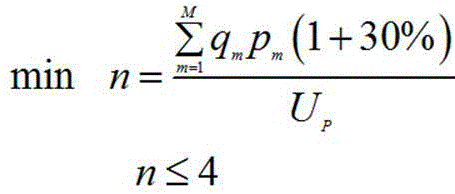
The functional board card of the testing machine has multiple specifications, the power of the power supply required by each specification is different, the functional board card in the machine table is firstly scanned after the power supply set is controlled to be powered on, the board card specifications of all slot positions are determined, the power required by the whole machine is calculated, then one or more power supplies meeting the requirements are turned on by the power supply of the functional board card according to the currently calculated power, and the optimal power supply efficiency is realized.
Power supply required by the board card:
wherein,
indicating the power supply power required by the board,
the number of the specification types of the board cards is shown,
is shown as
The number of the types of the board cards,
is shown as
The power of each kind of board card.
Power supply power supplied:
wherein,
presentation provisionThe power of the power source(s) of (c),
the power supply power of the power supply module of the functional board card is shown,
and the number of the required power modules of the functional board card is shown.
Minimum power supplied by the power supply:
therefore, the number of the required power modules of the functional board card is as follows:
example (c): the specification of each board card in the case is 1, and the power isASpecification 2 power ofBSpecification 3 Power isCThe number of the board cards is respectivelyX、Y、ZEach power supply having a power ofUp。
Power supply required by the board card:U1=AX+BY+CZ
power supply power supplied:U2=Up*n(n≤4)
minimum power supplied by the power supply:Umin=U1(1+30%)
the number of the power supplies needing to be started is obtained through the calculationn。
And 3, as shown in fig. 1, outputting the power modules of the parallel functional board cards through primary power filtering and primary power convergence.
As shown in fig. 5, the primary power filter is an n-type filter to reduce power ripples, and the primary power bus connects the power outputs of the plurality of functional board cards in parallel through the bus bar.
And 4, as shown in fig. 2, outputting the power after the primary confluence output through secondary power filtering and secondary power confluence.
And the secondary power supply filter is used for performing capacitance filter and reducing power supply ripples, and the secondary confluence is connected with the primary confluence output to supply power to each functional board card.
And 5, delivering the power output by the secondary power supply to the functional board card corresponding to the load.
A high-power control system of a mixed signal tester, as shown in fig. 3, includes a main power supply, a power supply subsystem, and a power supply output bus subsystem, wherein:
the main power supply is divided into a control power supply set and a function board card power supply set, and the control power supply set is monitored by an upper computer in real time. And the power supply set of the functional board card is controlled and monitored by an upper computer in real time. The functional board power supply pack comprises more than two functional board power modules.
As shown in fig. 1, the power supply subsystem includes a PCB a board, the PCB a board includes a primary power filter circuit and a primary power convergence output circuit, the functional board power modules are connected in parallel and then connected to the primary power filter circuit, and the primary power filter circuit is connected to the primary power convergence output circuit. The primary power supply confluence output circuit is connected with a confluence bar. The power supply is divided into a control power supply set and a functional board card power supply set.
As shown in fig. 2, the power output bus subsystem includes a PCB B board and a power management module, the PCB B board includes a secondary power filter circuit and a secondary power bus output circuit, the primary power bus output circuit, the secondary power filter circuit and the secondary power bus output circuit are sequentially connected, the secondary power bus output circuit is connected with a bus bar, and the bus bar supplies power to the functional board card corresponding to the load.
The power management module passesPMbusThe interface is connected with the FPGA chip of the PCB B board. The FPGA chip of the PCB B board is connected with an upper computer through an optical fiber and controlled by the upper computer.
The upper computer monitors the output voltage, current, temperature and the rotating speed of the power supply fan on line, when one or more indexes have large deviation, the power supply can be cut off immediately, an alarm prompt is sent, meanwhile, other power supplies work normally, the normal operation of the machine table is maintained, and the stability of the power supply of the whole system is improved.
In the invention, a power supply is a main power supply of the whole testing machine, and in order to realize the control of a power supply system, the main power supply is divided into two groups, one group is used as a control power supply group, and the other group is used as a functional board power supply group. The control power supply set is directly electrified, the upper computer performs real-time monitoring, and the functional board power supply set is controlled by the upper computer and monitors the power supply in real time.
The power supply pack is directly powered on, voltage is reduced through DC/DC, power is supplied to the FPGA, the FPGA communicates with a power supply through a PMbus, meanwhile, an FPGA chip is connected with a PCIE board card on a PC, and the power supply pack is controlled through a PC upper computer and monitors the state of the power supply.
The power of the power supply set of the functional board card depends on the specification of the rear-end functional board card, and the system supports the parallel connection of multi-stage power supplies. Therefore, the size of the power supply depends on the rear end plate card, the maximum power load usage is met according to the configuration of the machine, and then the machine starts the power supply meeting the requirements according to the number of the actually scanned card cards.
The control and monitoring of the power supply are mainly controlled by the FPGA and realized by the upper computer.
And after the functional board card power supply modules on the PCB A board are connected in parallel and output for converging and pi-shaped filtering, the functional board card power supply modules are output through the converging bar.
The power supply of the functional board card on the PCB B board is input through the bus bar and is transmitted to each functional board card, and the power supply management module passes throughPMbusThe interface is connected with the FPGA chip of the PCB B board, and the FPGA is connected with the PCIE board card through the optical fiber and controlled by the upper computer. And the power state is displayed on the upper computer in real time.
For a power supply at a load end of the functional board card, voltage reduction processing is carried out through DC/DC, for an FPGA power supply, 12V is firstly converted, then the voltage required by the FPGA is converted through LDO, and meanwhile, the power supply is required to be electrified sequentially. For the PE power supply, the power supply is firstly switched to 20V and-5V, then the power supply is switched to the voltage required by the PE through the LDO, and meanwhile, the power-on sequence of the power supply is required.
The parallel connection mode of the plurality of power supplies, the filtering of the output power supply, the control and monitoring of the power supplies, the confluence output of the plurality of power supplies and the implementation method of the rear end DC/DC provided by the invention meet the requirement of a testing machine on a high-power supply.
The above description is only of the preferred embodiments of the present invention, and it should be noted that: it will be apparent to those skilled in the art that various modifications and adaptations can be made without departing from the principles of the invention and these are intended to be within the scope of the invention.