Disclosure of Invention
In order to solve the problems in the prior art, the invention provides a cleaning robot which can realize various cleaning functions on a cleaning floor, such as sweeping, dust collection, mopping and a bactericidal lamp, when a cleaning area is cleaned, can also realize simple and convenient disassembly and assembly, can realize switching of various functions without turning over the cleaning robot, thereby greatly improving the cleaning efficiency of the cleaning robot and greatly improving the user experience of a user.
In order to achieve the purpose, the invention adopts the following technical scheme: the invention provides a cleaning robot, comprising:
the cleaning machine comprises a machine body, a cleaning driving module and a rolling brush driving module are arranged on the machine body; a walking mechanism is arranged on the machine body;
the floor cleaning component is detachable from the bottom of the machine body and is matched with the cleaning driving module on the machine body so that the floor cleaning component can rotate along with the rotation of the cleaning driving module;
the rolling brush component can be detached along the direction far away from the left side and the right side of the rolling brush driving module; the rolling brush component is tightly embedded in the rolling brush driving module so as to rotate along with the rotation of the rolling brush driving module;
and the dust and water spraying assembly is fastened in the machine body.
Further, the floor wiping assembly comprises:
mounting a plate;
the side brush is rotatably fastened on the mounting plate and is matched with the cleaning driving module so that the floor wiping component can be integrally detached from the machine body.
Further, the floor wiping assembly comprises:
mounting a plate;
a scrubbing assembly rotatably secured to the mounting plate and cooperating with the cleaning drive module such that the scrubbing assembly is integrally detachable from the housing.
Further, the floor wiping assembly comprises:
mounting a plate;
an ultraviolet lamp fastened to the mounting plate by a snap-fit manner such that the floor scrubber assembly is integrally detachable from the body.
Further, the floor scrubbing component can be detached from the machine body in a buckling mode.
Furthermore, at least one elastic clamping column is arranged on the floor scrubbing component; a bulge is arranged at one end of the elastic clamping column far away from the ground wiping component; the machine body is provided with a clamping hole; the elastic clamping column and the clamping hole can be mutually matched, clamped or disassembled.
Furthermore, the floor wiping component can be detached from the bottom of the machine body through the magnetic component.
Furthermore, at least one magnet is arranged on the floor scrubbing component; the machine body is provided with a magnet which is attracted with the magnet on the floor mop component at the position corresponding to the magnet on the floor mop component, so that the floor mop component is buckled with the machine body and can be detached.
Furthermore, extension rods are arranged on two sides of the rolling brush driving module; the two rollers are detachably inserted and tightly connected with the extension rod, so that the two rollers can rotate along with the rotation of the rolling brush driving module.
Further, the roller may be a rolling brush, a mop roller.
Furthermore, the roller is embedded in the extension rod through a buckling structure.
Further, the mounting plate is of a front-end concave structure.
Further, the traveling mechanism includes:
the two driving wheels are arranged on two sides of the bottom surface of the machine body;
the universal wheel is arranged at the front end of the bottom surface of the machine body;
the balance wheel is arranged at the rear end of the bottom surface of the machine body.
Furthermore, a sawtooth type strip scraper is arranged on a dust absorption opening of the dust absorption and water spray assembly.
Further, the dust-suction water-spray assembly includes:
a water tank;
the water spraying module is connected to the water tank; a water spraying pipe is arranged on the water spraying module; the dust-absorbing water-spraying component is provided with a dust-absorbing opening which is arranged above the rolling brush component and is matched with the rolling brush component so that garbage can be absorbed into the dust-absorbing water-spraying component from the dust-absorbing opening.
Further, the water tank is a purified water tank.
Further, the water tank includes a fresh water tank and a foul water tank. The rear end of the mop roller on the machine body is tightly provided with a scraping strip; a sewage collecting pipe is arranged in the middle of the scraping strip; the sewage collecting pipe is connected with the sewage tank through a pressure pump, so that the sewage after mopping is absorbed into the sewage tank.
Furthermore, a water spraying pipe port on the water spraying module is arranged on the machine body at the front end of the mop roller, so that water in the water tank is sprayed to the ground.
Further, a water spraying pipe port on the water spraying module is arranged on the machine body above the mop roller, so that water of the water tank is sprayed to the mop roller.
Compared with the prior art, the invention has the following advantages:
firstly, in general conditions, a user does not need to disassemble and assemble the floor wiping component frequently, for example, a traditional sweeper does not need to disassemble a side brush when cleaning every time, the floor wiping component can freely switch the cleaning mode of the cleaning robot through the modular design of the floor wiping component, the floor wiping component can wipe the floor and sterilize the floor, the installation is simple and convenient, and the user only needs to perform the modularized disassembly and installation of the whole function according to the own requirements; secondly, through the modular design of the rolling brush component, when the roller is replaced, a user does not need to turn over the cleaning robot, but the traditional floor mopping robot needs to clean the mop firstly when mopping the floor, and then needs to turn over the floor mopping machine, and the floor mopping frequency is high, so that the frequency of turning over the floor mopping machine by the user is high, and the floor mopping machine is inconvenient to use.
Drawings
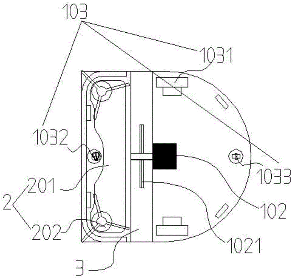
FIG. 1 is a first schematic view of a cleaning robot with a floor scrubbing assembly as an edge brush according to an embodiment of the present invention;
FIG. 2 is a schematic view of a modular construction of a floor scrubbing assembly of the cleaning robot in accordance with one embodiment of the present invention;
FIG. 3 is a second schematic structural view of the floor scrubbing assembly of the cleaning robot as an edge brush according to an embodiment of the present invention;
FIG. 4 is a third schematic structural view of the floor scrubbing assembly of the cleaning robot as an edge brush according to an embodiment of the present invention;
FIG. 5 is a fourth schematic structural view of the floor scrubbing assembly of the cleaning robot as an edge brush according to an embodiment of the present invention;
FIG. 6 is a first schematic view of a cleaning robot floor scrubbing assembly according to an embodiment of the present invention;
FIG. 7 is a schematic view of a modular construction of a robotic cleaning floor scrubbing assembly of an embodiment of the present invention;
FIG. 8 is a second schematic view of the cleaning robot floor scrubbing assembly of one embodiment of the present invention;
FIG. 9 is a third schematic view of the cleaning robot floor scrubbing assembly of one embodiment of the present invention;
FIG. 10 is a fourth schematic view of the cleaning robot floor scrubbing assembly of one embodiment of the present invention as a scrubbing assembly;
FIG. 11 is a first schematic view of a cleaning robot wiper assembly according to an embodiment of the present invention;
FIG. 12 is a schematic view of a modular construction of the cleaning robot floor scrubber assembly of one embodiment of the present invention with a UV lamp;
FIG. 13 is a second schematic view of the cleaning robot scrubber assembly of the present invention with the UV lamp;
FIG. 14 is a third schematic view of the cleaning robot scrubber assembly of the present invention with the UV lamp;
FIG. 15 is a fourth schematic view of the cleaning robot scrubber assembly of the present invention with the UV lamp;
FIG. 16 is a schematic view of a cleaning robot with a roller brush as an embodiment of the present invention;
FIG. 17 is a schematic view of a cleaning robot roller being a mop roller according to an embodiment of the present invention;
FIG. 18 is a schematic view of the interaction of the extension rod and the roller of the cleaning robot in accordance with one embodiment of the present invention;
FIG. 19 is a schematic view of a saw-tooth type strip blade of a cleaning robot in accordance with an embodiment of the present invention;
FIG. 20 is a schematic view of the water tank of the cleaning robot having a mop roller as a rolling brush assembly according to an embodiment of the present invention;
wherein, the symbols in the drawings are simply explained as follows:
1-machine body; 2-a floor wiping component; 3, rolling a brush component; 4, dust-absorbing water-spraying component; 5, scraping a blade; 101-cleaning a driving module; 102-a rolling brush driving module; 103-a traveling mechanism; 201-mounting plate; 202-side brushing; 203-a scrubbing assembly; 204-ultraviolet lamp; 302-roller; 303-buckling structure; 401-dust suction port; 402-dust box; 403-fan; 404-water tank; 405-a water spraying module; 406-scraping the strips; 2031-elastic clamp column; 2032-fastening holes; 2033 to a magnet; 1021-an extension rod; 3021 to a drum hole; 1031 to a driving wheel; 1032-universal wheels; 1033-balance wheel; 4041 parts of a water purification tank; 4042-a sewage tank; 4061 and sewage collecting pipe.
Detailed Description
In order to more fully understand the technical content of the present invention, the present invention will be further described with reference to the accompanying drawings, but not limited thereto.
The terminology used in the description of the one or more embodiments is for the purpose of describing the particular embodiments only and is not intended to be limiting of the description of the one or more embodiments. As used in one or more embodiments of the present specification and the appended claims, the singular forms "a," "an," and "the" are intended to include the plural forms as well, unless the context clearly indicates otherwise. It should also be understood that the term "and/or" as used in one or more embodiments of the present specification refers to and encompasses any and all possible combinations of one or more of the associated listed items.
Meanwhile, it will be understood by those skilled in the art that all terms (including technical and scientific terms) used herein, unless otherwise defined, have the same meaning as commonly understood by one of ordinary skill in the art to which this invention belongs. It will be further understood that terms, such as those defined in commonly used dictionaries, should be interpreted as having a meaning that is consistent with their meaning in the context of the prior art and will not be interpreted in an idealized or overly formal sense unless expressly so defined herein.
The cleaning robot applicable to the technical scheme of the invention can be (but is not limited to) automatic cleaning equipment such as a sweeping robot, a mopping robot or a sweeping and mopping integrated robot, and the robot can comprise a machine main body, a sensing system, a control system, a driving system, a cleaning system, an energy system and a human-computer interaction system.
Referring to fig. 1 to 20, the present invention provides a cleaning robot including:
the machine body 1 is provided with a cleaning driving module 101 and a rolling brush driving module 102 on the machine body 1. The body 1 is provided with a traveling mechanism 103. It should be understood that the front end of the machine body 1 is provided with an mechatronic collision case (not shown), and the lower end surface of the machine body 1 is provided with a plurality of sensors, such as infrared cliff sensors, for detecting the fall prevention of the cleaning robot. Or, the front end of the machine body 1 can be provided with no mechanical electronic collision shell, and a plurality of infrared distance measuring sensors can be arranged on the front end surface of the cleaning robot, and an artificial intelligence algorithm is combined, so that the detection of the obstacle in front of the main machine 1 is realized. The machine body 1 can be further provided with a laser radar, and the path planning of the cleaning area is realized by combining an artificial intelligence algorithm.
The floor scrubbing assembly 2 is detachably arranged at the bottom of the machine body 1 and is matched with the cleaning driving module 101 on the machine body 1 so that the floor scrubbing assembly 2 can rotate along with the rotation of the cleaning driving module 101. When the floor mopping assembly 2 needs to be disassembled or assembled, the machine body 1 needs to be turned over so as to disassemble or assemble the floor mopping assembly 2.
The rolling brush component 3, the rolling brush component 3 can be detached along the direction far away from the left and right sides of the rolling brush driving module 102. The invention adopts the structure that the rolling brush component 3 is detached relative to the left side and the right side of the machine body 1. The roller brush assembly 3 is tightly fitted to the roller brush driving module 102 so that it can rotate with the rotation of the roller brush driving module 102. The rolling brush component 3 can be disassembled from the two sides of the machine body 1 by a user without turning the machine body 1, and the rolling brush component 3 can be disassembled by taking out the rolling brush component 3 from the left side and the right side of the machine body 1. It should be understood that the roller brush driving module 102 is cooperatively connected with the roller brush assembly 3 through a gear box, so as to drive the roller brush assembly 3 to rotate.
The dust absorption water spray component 4 is fastened in the machine body 1. It will be appreciated that the floor scrubbing assembly 2 is a first cleaning of the floor and the roller brush assembly 3 is a second cleaning of the floor. Therefore, the double acting force cleaning of the cleaned ground is realized, and the cleaning is cleaner.
In an embodiment of the present invention, the floor wiping component 2 is detachable from the machine body 1 by a snap-fit manner. The floor scrubbing component 2 is provided with at least one elastic clamping column 2031. The elastic clamping column 2031 is provided with a bulge at one end far away from the ground wiping component 2. The body 1 is provided with a fastening hole 2032. The elastic clamping columns 2031 and the clamping holes 2032 can be mutually matched and clamped or disassembled. It should be understood that when the floor scrubbing assembly 2 is detachable from the body 1 by means of a buckle, at least one fastening hole is provided on the body 1, and an elastic fastening column 2031 is provided at a position of the floor scrubbing assembly 2 corresponding to the fastening hole, a protrusion is provided on the elastic fastening column 2031, and when the floor scrubbing assembly 2 is inserted into the fastening hole, the protrusion on the elastic fastening column 2031 and the fastening hole are fastened with each other, so that the floor scrubbing assembly 2 is fastened to the body 1; when the user lifts the floor scrubbing assembly 2, the elastic locking columns 2031 will make the floor scrubbing assembly 2 detach from the body 1 under the elastic action.
As shown in fig. 1, 6, 11 and 18, in an embodiment of the present invention, extending rods 1021 are disposed at two sides of the rolling brush driving module 102. The extension rod 1021 is a polygonal structure, but the present invention is not limited to this, and other polygonal structures, such as a hexagon, can be used. And may even be cylindrical.
Two rollers 302, the rollers 302 are detachably inserted into the extension rod 1021, so that the two rollers 302 can rotate along with the rotation of the roller brush driving module 102. It should be understood that the rollers 302 are provided with roller holes 3021, which are matched with the pentagonal structure of the extension rod 1021, so that the rollers 302 are tightly inserted into the extension rod 1021, and the two rollers 302 can rotate along with the rotation of the extension rod 1021. Wherein, the user can detach the left roller 302 from the left direction, i.e. the direction away from the extension rod 1021; the user can detach the right roller 302 by moving the right roller 302 to the right, i.e., away from the extension bar 1021.
As shown in fig. 18, in one embodiment of the invention, the roller 302 may be a rolling brush, mop roller. It will be appreciated that the roller brush comprises a shaft, a sleeve secured to the shaft, and a combination of a rubber wiper strip and a brush. When the roller brush is adopted, the roller brush is the same as a sweeper in the prior art, and the sweeping effect on the cleaning area required by the ground can be realized. When the mop roller is a mop roller, the mop roller comprises a sleeve and cleaning cotton wrapped on the sleeve. Wherein, the cleaning cotton can also be cotton cloth strip, and is implanted into the sleeve. The sleeve tube with the planted cleaning cotton can be tightly inserted into the extension rod 1021, so that the two rollers 302 can rotate along with the rotation of the roller brush driving module 102.
As shown in fig. 18, in an embodiment of the present invention, the roller 302 is embedded in the extension rod 1021 through a snap structure. So that the user only needs to insert the extension bar 1021 along two sides of the machine body 1 when assembling the roller 302. When disassembling, only the roller 302 needs to be disassembled along two sides of the extension rod 1021 of the machine body 1. The roller 302 is provided with a buckling column, the roller brush driving module 102 is provided with a buckling hole, and the buckling column and the buckling hole are matched to form a buckling structure.
As shown in fig. 8 and 9, in an embodiment of the present invention, the floor scrubbing assembly 2 is detachable from the bottom of the machine body 1 through a magnetic assembly. The floor scrubbing assembly 2 is provided with at least one magnet 2033. The machine body 1 is provided with a magnet which is attracted with the magnet 2033 on the floor scrubbing component 2 at the position corresponding to the magnet 2033 on the floor scrubbing component 2, so that the floor scrubbing component 2 is buckled with the machine body 1 and can be detached.
As shown in fig. 2, 7 and 12, in one embodiment of the present invention, the mounting plate 201 is a front concave structure. It should be understood that the present invention contemplates the mounting plate 201 as a front concave structure in order to bypass the universal wheels 1032 of the travel mechanism 103 and to act as a notch to facilitate grasping and tightening of the mounting plate 201 by the user.
As shown in fig. 1, 6, and 11, in an embodiment of the present invention, the traveling mechanism 103 includes:
two driving wheels 1031, the two driving wheels 1031 are disposed on two sides of the bottom surface of the machine body 1. It should be understood that the two driving wheels 1031 are driving wheels, which provide power for the entire cleaning robot to travel, and the two driving wheels 1031 of the present invention are divided into left and right wheels. However, both drive wheels 1031 may equally be crawler-type transmission wheels, or four drive wheels 1031.
Universal wheel 1032, universal wheel 1032 is placed at the front end of the bottom of the machine body 1. It should be understood that the universal wheels 1032 function to change the direction of travel for the body 1. In the prior art, a distance sensor can be arranged in the universal wheel and used for testing the stroke of the cleaning robot.
The balance wheel 1033 and the balance wheel 1033 are arranged at the rear end of the bottom surface of the machine body 1. It should be understood that the balance wheel 1033 functions to smoothly travel up or down a slope due to the balance wheel 1033 at the rear half of the body when the cleaning robot encounters up or down a slope. And the fault that the cleaning robot stops when the chassis scrapes the ground is avoided. Wherein the balance wheel 1033 employed in the present invention is not essential.
As shown in fig. 16, 17 and 19, in an embodiment of the present invention, a saw-toothed strip blade is disposed on the dust suction port 401 of the dust suction and water spray assembly 4. The material of the sawtooth type strip-shaped scraper 5 adopted by the invention is plastic, but not limited to the plastic, and the sawtooth type strip-shaped scraper can also be made of metal materials such as stainless steel and the like.
As shown in fig. 20, in an embodiment of the present invention, the dust suction water spray assembly 4 includes:
a water tank 404;
the water spraying module 405, the water spraying module 405 is connected to the water tank 404; the water spray module 405 is provided with a water spray pipe.
As shown in FIG. 20, in one embodiment of the invention, the water tank 404 may be the only fresh water tank 4041, and the fresh water tank 4041 functions to wet the floor or mop bowl when mopping.
As shown in fig. 20, in an embodiment of the present invention, the tank 404 may further include a fresh water tank 4041 and a foul water tank 4042. The rear end of the mop roller on the machine body 1 is tightly provided with a scraping strip 406; a sewage collecting pipe 4061 is arranged in the middle of the scraping strip 406; the sewage collecting pipe 4061 is connected to the sewage tank 4042 by a pressure pump, so that the sewage after mopping is absorbed into the sewage tank 4042. The clean water tank 4041 and the foul water tank 4042 may be formed as an integral container or may be formed as separate containers. The sewage collecting pipe 4061 plays a role of pumping sewage.
In one embodiment of the invention, as shown in fig. 20, a water spray nozzle on the water spray module 405 may be provided on the body 1 at the front end of the mop drum so that water from the water tank 404 is sprayed to the ground.
As shown in fig. 20, in an embodiment of the present invention, a water spray nozzle of the water spray module 405 may also be provided on the body 1 above the mop drum so that water of the water tank 404 is sprayed to the mop drum.
The first embodiment:
as shown in fig. 1 to 5, the floor wiping assembly 2 includes:
the mounting plate 201, the mounting plate 201 in the first embodiment of the present invention is provided with at least one fastener, and the fastener is matched with the fastening hole on the machine body 1, so as to fasten the mounting plate 201 on the machine body 1 by the fastener. And it does not necessarily adopt the snap structure, it can also be for attracting the magnetic combination, fasten at least one magnet 2033 on the mounting panel 201, and fasten at least one magnet 2033 on the position of magnet 2033 on the mounting panel 201 on the organism 1, thus realize fastening the mounting panel 201 on the organism 1 through the magnetic force.
A side brush 202, the side brush 202 being rotatably fastened to the mounting plate 201 and cooperating with the cleaning driving module 101 such that the floor scrubbing assembly 2 is integrally detachable from the body 1. It should be understood that the edge brush 202 of the first embodiment of the present invention is the same as the edge brush 202 of the sweeper in the prior art, and is composed of a chassis, a rubber strip and bristles. The adhesive tape is fixed on the chassis and protrudes out of the chassis, and the bristles are fastened on the adhesive tape. It can be screwed on the mounting plate 201 by a screw component, and can also be buckled on the mounting plate 201 by a buckling mode.
Second embodiment:
as shown in fig. 6 to 10, the floor wiping assembly 2 includes:
the mounting plate 201, the mounting plate 201 in the first embodiment of the present invention is provided with at least one fastener, and the fastener is matched with the fastening hole on the machine body 1, so as to fasten the mounting plate 201 on the machine body 1 by the fastener. And it does not necessarily adopt the snap structure, it can also be for attracting the magnetic combination, fasten at least one magnet 2033 on the mounting panel 201, and fasten at least one magnet 2033 on the position of magnet 2033 on the mounting panel 201 on the organism 1, thus realize fastening the mounting panel 201 on the organism 1 through the magnetic force.
A scrubbing assembly 203, the scrubbing assembly 203 being rotatably secured to the mounting plate 201 and cooperating with the cleaning drive module 101 such that the scrubbing assembly 2 is integrally detachable from the body 1. It should be understood that the scrubbing assembly 203 is used for scrubbing the floor of the area to be cleaned, and in view of the fact that the floor is inevitably polluted in daily life, the floor is easy to generate stains after the polluted water is dried due to the fact that the floor is not cleaned for a long time, the stains are adhered to the floor, and the stains are difficult to clean by a common sweeper and a mop, so that the stains need to be scrubbed repeatedly, and the cleaning efficiency is low. In a second embodiment of the invention, four scrubbing assemblies 203 are used, the four scrubbing assemblies 203 being comprised of bristle carriers and bristles secured to the bristle carriers. The bristles are embedded in the bristle bearing plate by a production process. The bristle carrier plate has a through hole in the middle for rotatably fixing the scrubbing unit 203 to the mounting plate 201 and for cooperating with the cleaning driving module 101.
The third embodiment:
as shown in fig. 11 to 15, the floor wiping assembly 2 includes:
the mounting plate 201, the mounting plate 201 in the first embodiment of the present invention is provided with at least one fastener, and the fastener is matched with the fastening hole on the machine body 1, so as to fasten the mounting plate 201 on the machine body 1 by the fastener. It also need not necessarily adopt the snap structure, but also can be a magnetic combination, at least one magnet 2033 is fastened on the mounting plate 201, and at least one magnet 2033 is fastened on the body 1 at the position of the magnet 2033 on the mounting plate 201, thereby realizing that the mounting plate 201 is fastened on the body 1 by magnetic force.
An ultraviolet lamp 204, the ultraviolet lamp 204 being fastened to the mounting plate 201 by means of a snap-fit so that the floor wiping assembly 2 is entirely detachable from the body 1. It should be appreciated that the ultraviolet lamp 204 is intended to act as a germicidal action on the floor being cleaned. Which snap-fit onto mounting plate 201. When the broadcasting main machine of the machine body 1 is suspended, the ultraviolet lamp 204 does not work under the control of the control unit (not shown); when the main body 1 does not broadcast the suspension of the main body, the ultraviolet lamp 204 is turned on to sterilize the ground. Wherein, be equipped with an at least recess on the mounting panel 201 to be equipped with on the mounting panel 201 and connect the electric arch, mutually support with two electricity connection recesses on the organism 1, thereby realize the circular telegram of ultraviolet lamp 204. Two grooves are designed in the invention as sockets for the ultraviolet lamp 204, and the ultraviolet lamp 204 can be arranged in the sockets of the grooves on the mounting plate 201.
It will be appreciated that when the scrubbing assembly 2 is used for the sanitizing function, the user should replace the mounting plate 201 with the ultraviolet lamp 204 to achieve a sanitizing coverage of the entire cleaning area as the cleaning robot walks. The operation principle is that when the cliff sensor of the cleaning robot detects the principle ground of the machine body 1, namely the machine body 1 is suspended, the main control chip receives a machine body suspension signal sent by the cliff sensor, and therefore power supply of the power supply to the ultraviolet lamp 204 is cut off. Thereby preventing the user from being injured by the direct irradiation of the ultraviolet lamp to the eyes, skin, etc. of the user due to carelessness of the user.
In the embodiment of the present invention, the dust-absorbing water-spraying component 4 is provided with a dust-absorbing opening 401 disposed above the rolling brush component 3 and cooperating with the rolling brush component 3 to enable garbage to be absorbed into the dust-absorbing water-spraying component 4 from the dust-absorbing opening 401. When the user employs a sweeping function, i.e., the roller 302 is a roller brush. The dust-collecting water-spraying assembly 4 in the embodiment of the invention comprises a dust-collecting opening 401, a dust box 402 and a fan 403, wherein the dust-inlet on the dust box 402 is matched with the dust-collecting opening 401 correspondingly, the fan 403 is arranged at the rear end of the dust box 402 and connected with the dust box 402, when the dust-collecting water-spraying assembly is used, a user puts the dust box 402 into a cleaning robot, and the fan 403 is started to suck garbage into the dust box 402 from the dust-collecting opening 401.
In an embodiment of the invention, when the user is using a mopping function, i.e. the roller 302 is a mop roller. The dust collection and water spray assembly 4 in the embodiment of the invention comprises a water tank 404 and a water spray module 405, wherein the water tank 404 is a pure water tank, and the water spray module 405 is arranged at the front end of the water tank 404 and is connected with the water tank 404. When the mop is used, a user puts the water tank 404 into the cleaning robot, the water spraying module 405 pumps water out of the water tank 404 and sprays the water to the front ground of the mop roller, so that the mopping function is realized, but the mop is not limited to the above, and the water spraying module 405 can also pump water out of the water tank 404 and spray the water onto the mop roller to wet the mop roller, so that the mopping function is realized. Wherein the water spray module 405 may be a hydraulic pump. It should be understood that the water tank 404 may be formed by combining a foul water tank 4042 and a fresh water tank 4041, and a scraping strip 406 is provided behind the drum 302 on the machine body 1, and the scraping strip 406 may be made of a rubber material. The wiper strip 406 is provided with a sewage absorbing pipe connected to a sewage tank 4042 through a hydraulic pump, thereby realizing the function of collecting sewage while mopping the floor. Wherein, the water spray module 405, the scraping bar 406 and the sewage collecting pipe 4061 are fastened on the machine body 1, and when the dust box 402 is replaced with the water tank 404, a user only needs to take out the dust box 402, and then the water tank 404 is integrally put in.
Firstly, in general conditions, a user does not need to disassemble and assemble the floor wiping component 2 frequently, for example, a traditional sweeper does not need to disassemble the side brush 202 during cleaning each time, the floor wiping component 2 can freely switch the cleaning mode of the cleaning robot through the modular design of the floor wiping component 2, the floor wiping component 2 can wipe the floor and sterilize the floor, the installation is simple and convenient, and the user only needs to carry out the modularized disassembly and installation of the whole function according to the requirement; secondly, through the modular design of the rolling brush component 3, when the roller 302 is replaced, a user does not need to turn over the cleaning robot, but the traditional floor mopping robot needs to clean the mop firstly when mopping the floor, and the floor mopping machine needs to be turned over at the moment, because the floor mopping frequency is high, the frequency of turning over the floor mopping machine by the user is high, and the cleaning robot is inconvenient to use, and the cleaning robot can be replaced only by drawing the roller 302 out to two sides of the cleaning robot. Meanwhile, the roller 302 can be switched into a rolling brush mode and a mop roller mode, so that the function of the cleaning robot can be switched by a user.
The above specific embodiments are merely illustrative of the inventive concept and many modifications and variations may be made by those skilled in the art without departing from the inventive concept. Such modifications and variations are intended to be included within the scope of the present invention.