CN114242518A - Improved large-load low-temperature-rise magnetic latching contactor - Google Patents
Improved large-load low-temperature-rise magnetic latching contactor Download PDFInfo
- Publication number
- CN114242518A CN114242518A CN202210035638.3A CN202210035638A CN114242518A CN 114242518 A CN114242518 A CN 114242518A CN 202210035638 A CN202210035638 A CN 202210035638A CN 114242518 A CN114242518 A CN 114242518A
- Authority
- CN
- China
- Prior art keywords
- static
- spring plate
- movable
- contact
- plate contact
- Prior art date
- Legal status (The legal status is an assumption and is not a legal conclusion. Google has not performed a legal analysis and makes no representation as to the accuracy of the status listed.)
- Pending
Links
Images






Classifications
-
- H—ELECTRICITY
- H01—ELECTRIC ELEMENTS
- H01H—ELECTRIC SWITCHES; RELAYS; SELECTORS; EMERGENCY PROTECTIVE DEVICES
- H01H50/00—Details of electromagnetic relays
- H01H50/02—Bases; Casings; Covers
-
- H—ELECTRICITY
- H01—ELECTRIC ELEMENTS
- H01H—ELECTRIC SWITCHES; RELAYS; SELECTORS; EMERGENCY PROTECTIVE DEVICES
- H01H50/00—Details of electromagnetic relays
- H01H50/12—Ventilating; Cooling; Heating
-
- H—ELECTRICITY
- H01—ELECTRIC ELEMENTS
- H01H—ELECTRIC SWITCHES; RELAYS; SELECTORS; EMERGENCY PROTECTIVE DEVICES
- H01H50/00—Details of electromagnetic relays
- H01H50/16—Magnetic circuit arrangements
-
- H—ELECTRICITY
- H01—ELECTRIC ELEMENTS
- H01H—ELECTRIC SWITCHES; RELAYS; SELECTORS; EMERGENCY PROTECTIVE DEVICES
- H01H50/00—Details of electromagnetic relays
- H01H50/54—Contact arrangements
Landscapes
- Physics & Mathematics (AREA)
- Electromagnetism (AREA)
- Electromagnets (AREA)
Abstract
The invention discloses an improved large-load low-temperature-rise magnetic latching contactor, which comprises a base, a yoke iron shell, an electromagnetic assembly, a yoke iron plate, a push rod frame, a static spring plate, a movable spring plate contact assembly and the like, wherein each static spring plate and each movable spring plate contact assembly are respectively designed into a double-reed laminated riveting structure, so that two reeds simultaneously play a current-carrying role, the thickness of the reed plate is increased to increase the current-carrying sectional area, the heating of the reed plate is reduced, the temperature rise is reduced, and the width of the reed plate can be reduced to reduce the appearance of a product under the condition of ensuring the current-carrying sectional area requirement corresponding to the load; meanwhile, each static spring plate is provided with at least three static contacts, and the push rod frame is provided with at least three movable spring plate contact assemblies to form equal number, so that multiple groups of contact which are contacted and connected are in parallel conductive connection or are separated and disconnected from the conductive connection, the current and the contact heating through the single group of contact are reduced, the contacts are kept in a low-temperature rise state, and the advantages of eliminating potential safety hazards in use, prolonging the service life and the like are achieved.
Description
Technical Field
The invention relates to a magnetic latching contactor, in particular to an improved large-load low-temperature-rise magnetic latching contactor.
Background
At present, the structure of a magnetic latching contactor mainly comprises a base, a yoke iron shell installed on the base, an electromagnetic assembly installed in the yoke iron shell, a push rod frame movably arranged below the electromagnetic assembly, and the like, wherein a pair of static spring plates are arranged on the base, a pair of moving spring plate contact assemblies are arranged on the push rod frame, and a yoke iron plate fixedly installed and separating the electromagnetic assembly and the push rod frame is arranged in the yoke iron shell; therefore, when the electromagnetic assembly is connected to be not less than the rated excitation pulse voltage, the push rod frame is driven to descend, and the pair of movable spring plate contact assemblies are synchronously driven to contact the pair of static spring plates, so that the conductive connection between the pair of static spring plates is connected; when the electromagnetic assembly is switched on and is not less than the rated excitation pulse voltage, the push rod frame is driven to ascend, and the pair of movable spring plate contact assemblies are synchronously driven to be separated from the pair of static spring plates, so that the conductive connection between the pair of static spring plates is disconnected. However, each static spring plate and each moving spring plate contact assembly of the conventional magnetic latching contactor are of a single-piece structure, and two contacts are designed on each static spring plate or moving spring plate contact assembly of the single-piece structure, that is, two groups of contacts are connected or disconnected between the static spring plate and the moving spring plate contact assembly, so that in practical use, many problems can be found: firstly, the current-carrying sectional area of a static spring plate and a moving spring plate contact assembly of a single-chip structure is small, so that a large current-carrying effect cannot be achieved, and the spring plate is easy to generate heat and rise temperature; secondly, only a pair of static spring plates and a pair of moving spring plate contact assemblies are connected or disconnected, so that the current passing through a single group of contacts is difficult to reduce, and the contact heating and temperature rise are increased; and thirdly, the outer surface of each static spring plate is not subjected to heat dissipation treatment, and the heating and temperature rise of the static spring plate can be caused. Therefore, the problems of heating and temperature rise of the spring plate and the contact cannot be effectively solved, the service life of a product can be shortened, and great potential safety hazards are brought to product use.
Disclosure of Invention
The invention aims to overcome the defects of the prior art and provide an improved large-load low-temperature-rise magnetic latching contactor which can effectively reduce heating and temperature rise, eliminate potential safety hazards in use and prolong the service life of a product.
The technical problem of the invention is realized by the following technical scheme:
an improved large-load low-temperature-rise magnetic latching contactor comprises a base, a yoke iron shell, an electromagnetic assembly, a push rod frame and a yoke iron plate, wherein the yoke iron shell is installed on the base, the electromagnetic assembly is installed in the yoke iron shell, the push rod frame is movably arranged below the electromagnetic assembly, and the yoke iron plate is fixedly installed in the yoke iron shell and separates the electromagnetic assembly from the push rod frame; the base is provided with a pair of static spring plates, and the push rod frame is provided with a plurality of movable spring plate contact assemblies; the electromagnetic assembly is connected with a rated excitation pulse voltage to drive the push rod frame to descend, and synchronously drives the plurality of movable spring plate contact assemblies to contact the pair of static spring plates, so that the conductive connection between the pair of static spring plates is connected; the electromagnetic assembly is connected with a rated excitation pulse voltage to drive the push rod frame to ascend, and synchronously drives the plurality of movable spring plate contact assemblies to separate from the pair of static spring plates, so that the conductive connection between the pair of static spring plates is disconnected, each static spring plate is formed by vertically laminating and riveting at least two static spring pieces into a whole, and each movable spring plate contact assembly is formed by vertically laminating and riveting at least two movable spring pieces into a whole; each static spring plate is provided with at least three static contacts, at least three movable spring plate contact assemblies are correspondingly arranged on the push rod frame, the number of the movable spring plate contact assemblies is equal to that of the static contacts on each static spring plate, and the at least three movable spring plate contact assemblies and the at least three static contacts on each static spring plate form a plurality of groups of contact parallel conductive connection or disconnection conductive connection of contact connection.
Each static spring plate is formed by vertically laminating and riveting at least two static springs into a whole, the outer static spring is exposed out of the base part and has a wider heat dissipation surface compared with the inner static spring, and the heat dissipation surface is further subjected to groove pressing treatment or embossing treatment or is coated with heat dissipation materials.
Each static spring plate is provided with a first static contact, a second static contact and a third static contact, a push rod frame is correspondingly provided with a first movable spring plate contact assembly, a second movable spring plate contact assembly and a third movable spring plate contact assembly, the first movable spring plate contact assembly is provided with a pair of first movable contacts, the second movable spring plate contact assembly is provided with a pair of second movable contacts, and the third movable spring plate contact assembly is provided with a pair of third movable contacts; a pair of first movable contacts on the first movable spring plate contact assembly is connected with or disconnected from first fixed contacts on a pair of fixed spring plates, a pair of second movable contacts on the second movable spring plate contact assembly is connected with or disconnected from second fixed contacts on the pair of fixed spring plates, and a pair of third movable contacts on the third movable spring plate contact assembly is connected with or disconnected from third fixed contacts on the pair of fixed spring plates.
The push rod frame descends to drive the first movable spring plate contact assembly, the second movable spring plate contact assembly and the third movable spring plate contact assembly to descend synchronously, and the first movable contact, the second movable contact and the third movable contact form simultaneous conduction with the first fixed contact, the second fixed contact and the third fixed contact or are sequentially conducted; the push rod frame ascends to drive the first movable spring plate contact assembly, the second movable spring plate contact assembly and the third movable spring plate contact assembly to ascend synchronously, the first movable contact, the second movable contact and the third movable contact form simultaneous disconnection conduction or successive disconnection conduction with the first fixed contact, the second fixed contact and the third fixed contact, and the disconnection conduction sequence is related to the designed connection conduction sequence.
The bottom of the push rod frame is provided with a support fixed by buckling, the first movable spring plate contact assembly, the second movable spring plate contact assembly and the third movable spring plate contact assembly are horizontally arranged in the support in a lifting and movable mode side by side, large springs pushed mutually are arranged between the first movable spring plate contact assembly and the push rod frame, and small springs pushed mutually are arranged between the second movable spring plate contact assembly and the push rod frame and between the third movable spring plate contact assembly and the push rod frame.
The support be the U type support, the both sides of this U type support are equipped with respectively to tear the partition frame that bends and be the U type form, and the partition frame spiral-lock dress is outside second movable spring board contact subassembly to separate second movable spring board contact subassembly and first movable spring board contact subassembly, second movable spring board contact subassembly and third movable spring board contact subassembly respectively.
The electromagnetic assembly comprises a coil rack, an upper coil, a lower coil and a magnetic block, wherein the upper coil and the lower coil are sleeved and fixed outside the coil rack; an upper static iron core is fixedly arranged in the upper coil, a lower static iron core is fixedly arranged in the lower coil, and a movable iron core is movably arranged between the upper static iron core and the lower static iron core; the top of the push rod frame is provided with a push rod which extends upwards and is connected with the movable iron core; the electromagnetic assembly is connected with a rated excitation pulse voltage to form instant electromagnetic attraction, the instant electromagnetic attraction absorbs the movable iron core to disappear after the movable iron core descends, the descending movable iron core is kept to be attached to the lower static iron core by the synchronous matching of the magnetic force of the magnetic block, and the movable iron core drives the push rod frame to descend through the push rod; the electromagnetic assembly is connected with a rated excitation pulse voltage to form instant electromagnetic attraction, or the instant electromagnetic attraction absorbs the movable iron core to disappear after rising, the magnetic force of the magnetic block is synchronously matched to keep the rising movable iron core to be attached to the static iron core, and the movable iron core drives the push rod frame to rise through the push rod.
The instant electromagnetic attraction of the electromagnetic assembly is greater than the magnetic force of the magnetic block, and when the magnetic force of the magnetic block keeps the movable iron core attached to the upper static iron core, the instant electromagnetic attraction overcomes the magnetic force of the magnetic block and adsorbs the movable iron core to be separated from the upper static iron core and descend; when the magnetic force of the magnetic block keeps the movable iron core attached to the lower static iron core, the instant electromagnetic attraction overcomes the magnetic force of the magnetic block and adsorbs the movable iron core to be separated from the lower static iron core to ascend.
Compared with the prior art, each static spring plate forming the magnetic latching contactor is designed to be vertically overlapped and riveted into a whole by at least two static spring pieces, and each movable spring plate contact assembly is designed to be vertically overlapped and riveted into a whole by at least two movable spring pieces; meanwhile, each static spring plate is provided with at least three static contacts, and the push rod frame is correspondingly provided with at least three movable spring plate contact assemblies, namely the number of the movable spring plate contact assemblies is equal to that of the static contacts on each static spring plate; thus, the at least three movable spring plate contact assemblies and the at least three static contacts on each static spring plate can form contact connection of multiple groups of contact points in parallel or separate from disconnection of the contact points. In summary, the static spring plate and the movable spring plate contact assembly adopting the double-reed laminated rivet structure has the advantages that as the two reeds simultaneously play a role in current carrying, the current carrying sectional area is increased by increasing the thickness of the reeds, the heat of the reed plate is reduced, the temperature rise is reduced, and the width of the reed plate can be reduced to enable the appearance design of a product to be smaller and more exquisite under the condition of ensuring the current carrying sectional area required by the corresponding load; in addition, the connection or disconnection of the three groups of contacts can better reduce the current passing through the single group of contacts, thereby reducing the heating of the contacts and keeping the contacts in a lower temperature rise state all the time. Obviously, the improved large-load low-temperature-rise magnetic latching contactor can eliminate potential safety hazards in use and prolong the service life of products.
Drawings
Fig. 1 is a schematic sectional structure of the present invention.
Fig. 2 is an exploded perspective view of fig. 1.
Fig. 3 is a perspective view of the installation structure of the push rod frame and the three moving spring plate contact assemblies.
Fig. 4 is a structural schematic diagram of the stent.
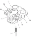
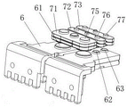
Fig. 5 is a schematic diagram of the position structure of three moving spring plate contact assemblies and a pair of static spring plates.
Fig. 6 is a perspective view of fig. 5.
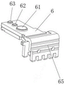
FIG. 7 is a schematic structural view of the stationary spring (the heat dissipating surface is processed by grooving).
Fig. 8 is an exploded perspective view of fig. 7.
Fig. 9 is a schematic structural view of the stationary spring plate (the heat radiating surface is subjected to embossing treatment).
Fig. 10 is a schematic structural view of the first moving spring plate contact assembly.
Fig. 11 is a perspective view of fig. 10.
Detailed Description
The embodiments of the present invention will be described in detail below with reference to the above drawings.
As shown in the figures 1-11, 1 is a base, 11 is a rotation preventing rod, 12 is a socket, 2 is a yoke iron shell, 21 is a pin, 22 is a top hole, 3 is an electromagnetic component, 31 is a coil rack, 311 is a shaft hole, 312 is a embedding hole, 32 is an upper coil, 33 is a lower coil, 34 is a magnetic block, 35 is an upper static iron core, 36 is a lower static iron core, 37 is a movable iron core, 38 is a magnetic separation sheet, 4 is a push rod rack, 41 is a push rod, 5 is a yoke iron plate, 51 is a bottom hole, 6 is a static spring plate, 61 is a first static contact, 62 is a second static contact, 63 is a third static contact, 64 is a static spring plate, 65 is a radiating surface, 71 is a first movable spring plate contact component, 72 is a second movable spring plate contact component, 73 is a third movable spring plate contact component, 74 is a bracket, 741 is a movable frame, 75 is a first movable contact, 76 is a second movable contact, 77 is a third movable contact, 78 is a large spring plate, 79 is a small spring plate, 70 is a movable spring plate, 70, 8. Coil terminal, 9. shell.
An improved magnetic latching contactor with large load and low temperature rise is mainly related to a magnetic latching contactor suitable for being used under large load, as shown in fig. 1 and fig. 2, the structure of the magnetic latching contactor is composed of a base 1, a yoke iron shell 2, an electromagnetic component 3, a yoke iron plate 5, a push rod frame 4 and the like, and the base 1 is further provided with a shell 9 which can cover the yoke iron shell 2 and related components to form protection.
The yoke shell 2 is in an inverted U shape and is correspondingly inserted into the sockets 12 on the two sides of the base 1 through the pins 21 on the two sides to form fixation; electromagnetic component 3 and push rod frame 4 set up in yoke shell 2 according to the mode of upper and lower overall arrangement to separate through yoke plate 5 of horizontal fixed mounting in yoke shell 2, make push rod frame 4 can form the activity setting under electromagnetic component 3.
As shown in fig. 2, the electromagnetic assembly 3 includes a coil rack 31, an upper coil 32 and a lower coil 33 sleeved and fixed outside the coil rack, and a magnetic block 34 installed between the upper and lower coils, specifically: an up-down through shaft hole 311 is arranged in the coil rack 31, and the upper coil 32, the magnetic block 34 and the lower coil 33 are sequentially sleeved and fixed outside the shaft hole 311 from top to bottom; meanwhile, the upper stationary core 35, the magnetism isolating sheet 38, the movable core 37 and the lower stationary core 36 are also sequentially installed in the shaft hole 311 in the order from top to bottom, and the upper stationary core 35 is fixed to the top hole 22 of the yoke iron case 2, that is, just fixed to the upper coil 32, and the lower stationary core 36 is fixed to the bottom hole 51 of the yoke iron plate 5, that is, just fixed to the lower coil 33, so that once the electromagnetic assembly 3 is energized, the movable core 37 is attracted to form descending or ascending by generating electromagnetic attraction force through the upper and lower stationary cores, and the coil terminal 8 for electrically connecting the electromagnetic assembly 3 is arranged on the coil frame 31.
The pair of magnetic blocks 34 are provided with a pair of magnetic steels, usually magnetic steels with strong magnetic force are selected, and the pair of magnetic blocks 34 are symmetrically embedded in the embedding holes 312 on the coil rack 31 by taking the shaft hole 311 as a center and provide fixed magnetic force.
Of course, the shaft sleeve is not designed in the actual structure, so that the shaft sleeve is mainly suitable for the working condition with low frequency requirement, and the purpose of adding the shaft sleeve is to prolong the service life of the machine when the operation frequency is frequent.
The support 74 is a U-shaped support, two sides of the U-shaped support are respectively provided with a separating frame 741 which is torn and bent into a U shape, and the separating frame is buckled outside the second moving spring plate contact assembly 72 and respectively separates the second moving spring plate contact assembly from the first moving spring plate contact assembly 71, and the second moving spring plate contact assembly from the third moving spring plate contact assembly 73, so that the first moving spring plate contact assembly 71, the second moving spring plate contact assembly 72 and the third moving spring plate contact assembly 73 can be limited to only move up and down in the support 74 through the separating frame 741, and the overlapping interference condition during the relative motion among the three moving spring plate contact assemblies can be prevented.
The base 1 is also provided with rotation preventing rods 11 respectively located on both sides of the bracket 74, and the rotation preventing rods on both sides mainly play a role in positioning the bracket 74 and preventing the bracket from rotating together, so that the bracket 74 can only move up and down in actual work.
Each movable spring plate contact assembly is formed by vertically overlapping and riveting at least two movable springs 70 into a whole, a pair of first movable contacts 75 is arranged on the first movable spring plate contact assembly 71, a pair of second movable contacts 76 is arranged on the second movable spring plate contact assembly 72, a pair of third movable contacts 77 is arranged on the third movable spring plate contact assembly 73, a pair of static spring plates 6 are correspondingly required to be arranged on the base 1, each static spring plate is formed by vertically overlapping and riveting at least two static springs 64 into a whole, at least three static contacts are arranged on each static spring plate 6, the first static contact 61, the second static contact 62 and the third static contact 63 are respectively arranged in the embodiment, and the design number of the static contacts on each static spring plate 6 is equal to that of the movable spring plate contact assemblies.
Thus, the pair of first movable contacts 75 of the first movable spring plate contact assembly 71 are connected to or disconnected from the first stationary contacts 61 of the pair of stationary spring plates 6, the pair of second movable contacts 76 of the second movable spring plate contact assembly 72 are connected to or disconnected from the second stationary contacts 62 of the pair of stationary spring plates 6, and the pair of third movable contacts 77 of the third movable spring plate contact assembly 73 are connected to or disconnected from the third stationary contacts 63 of the pair of stationary spring plates 6.
In practical operation, when the push rod frame 4 descends to drive the first movable spring plate contact assembly 71, the second movable spring plate contact assembly 72 and the third movable spring plate contact assembly 73 to descend synchronously, the first movable contact 75, the second movable contact 76 and the third movable contact 77, the first fixed contact 61, the second fixed contact 62 and the third fixed contact 63 can be designed to be connected and conducted simultaneously or sequentially as required.
On the contrary, when the push rod frame 4 ascends to drive the first moving spring plate contact assembly 71, the second moving spring plate contact assembly 72 and the third moving spring plate contact assembly 73 to ascend synchronously, the first moving contact 75, the second moving contact 76 and the third moving contact 77, the first fixed contact 61, the second fixed contact 62 and the third fixed contact 63 can be designed to be simultaneously disconnected or sequentially disconnected according to requirements, and the disconnection conduction sequence is related to the designed connection conduction sequence.
Meanwhile, each of the static spring plates 6 is formed by at least two static spring pieces 64 which are laminated and riveted together, and the outer static spring piece is exposed on the base 1 portion and has a wider heat dissipation surface 65 than the inner static spring piece, which is further processed by grooving as shown in fig. 7 or embossing or coating with a heat dissipation material as shown in fig. 9. Of course, the purpose of the indent or the emboss is to increase the surface area to accelerate the heat dissipation, so the processing method is not limited thereto, and other similar surface area increasing processes are also applicable.
The working process of the invention is as follows: when the electromagnetic assembly 3 is switched on and is not less than the rated excitation pulse voltage to form instant electromagnetic attraction, the instant electromagnetic attraction absorbs the movable iron core 37 and disappears after the movable iron core 37 descends, the descending movable iron core 37 is kept attached to the lower static iron core 36 through the synchronous matching of the magnetic force of the magnetic block 34, the descending movable iron core 37 can drive the push rod frame 4 to descend through the push rod 41, and synchronously drive the first movable spring plate contact assembly 71, the second movable spring plate contact assembly 72 and the third movable spring plate contact assembly 73 to contact the pair of static spring plates 6, so that the conductive connection between the pair of static spring plates 6 is switched on; when the electromagnetic assembly 3 is switched on and not less than the rated excitation pulse voltage to form instant electromagnetic attraction, the instant electromagnetic attraction absorbs the movable iron core 37 and disappears after the movable iron core 37 ascends, the magnetic force of the magnetic block 34 is synchronously matched to keep the ascending movable iron core 37 attached to the upper static iron core 35, at the moment, the ascending movable iron core 37 can drive the push rod frame 4 to ascend through the push rod 41, and synchronously drive the third movable spring plate contact assembly 73, the second movable spring plate contact assembly 72 and the first movable spring plate contact assembly 71 to be separated from the pair of static spring plates 6, so that the conductive connection between the pair of static spring plates 6 is disconnected.
Obviously, the instant electromagnetic attraction of the electromagnetic assembly 3 in the above working process needs to be greater than the magnetic force of the magnetic block 34, and when the magnetic force of the magnetic block keeps the movable iron core 37 attached to the upper stationary iron core 35, the instant electromagnetic attraction will overcome the magnetic force of the magnetic block 34 and attract the movable iron core 37 to be separated from the upper stationary iron core 35 and descend; when the magnetic force of the magnetic block 34 keeps the movable iron core 37 attached to the lower stationary iron core 36, the instant electromagnetic attraction force overcomes the magnetic force of the magnetic block 34 and attracts the movable iron core 37 to be separated from the lower stationary iron core 36 and rise.
Because the electromagnetic attraction of the electromagnetic component 3 is instantaneous electromagnetic attraction, the coil is not required to be electrified permanently, and the movable iron core 37 is attached to the upper and lower static iron cores and is kept by the magnetic force of the magnetic block 34 in a synchronous matching manner, so that the coil enameled wire can be effectively prevented from being electrified for a long time to generate heat, the influence on the insulating property of a paint film of the coil enameled wire can be reduced, and turn-to-turn short circuit and coil burnout are also avoided.
The at least three moving spring plate contact assemblies and the at least three static contacts on each static spring plate 6 form a plurality of groups of contact parallel conductive connection or disconnection conductive connection, the multi-group contact parallel structure can better perform parallel shunting, and the current of a single group of contacts is greatly reduced, so that the contact heating is reduced, and the contacts are always kept in a lower temperature rise state
In addition, the contact assembly of the static spring plate and the movable spring plate in the double-reed overlapped riveting structure is adopted, and then the contacts are riveted on the two leaf springs simultaneously, so that the two leaf springs can play a current-carrying role simultaneously, the thickness of the spring plate can be increased and the current-carrying sectional area can be increased by the two leaf springs, the spring plate can generate less heat and reduce the temperature rise, and meanwhile, under the condition that the requirement of the current-carrying sectional area required by the corresponding load is guaranteed, the width of the spring plate can be reduced to enable the appearance design of a product to be smaller and more exquisite. Obviously, the structural improvements can better eliminate the potential safety hazard of the magnetic latching contactor and prolong the service life of the product.
The above description is only a specific embodiment of the present invention, and those skilled in the art should understand that any similar structural design to the embodiment is included in the protection scope of the present invention.
Claims (8)
Priority Applications (1)
| Application Number | Priority Date | Filing Date | Title |
|---|---|---|---|
| CN202210035638.3A CN114242518A (en) | 2022-01-13 | 2022-01-13 | Improved large-load low-temperature-rise magnetic latching contactor |
Applications Claiming Priority (1)
| Application Number | Priority Date | Filing Date | Title |
|---|---|---|---|
| CN202210035638.3A CN114242518A (en) | 2022-01-13 | 2022-01-13 | Improved large-load low-temperature-rise magnetic latching contactor |
Publications (1)
| Publication Number | Publication Date |
|---|---|
| CN114242518A true CN114242518A (en) | 2022-03-25 |
Family
ID=80746540
Family Applications (1)
| Application Number | Title | Priority Date | Filing Date |
|---|---|---|---|
| CN202210035638.3A Pending CN114242518A (en) | 2022-01-13 | 2022-01-13 | Improved large-load low-temperature-rise magnetic latching contactor |
Country Status (1)
| Country | Link |
|---|---|
| CN (1) | CN114242518A (en) |
Cited By (2)
| Publication number | Priority date | Publication date | Assignee | Title |
|---|---|---|---|---|
| CN115966441A (en) * | 2023-01-05 | 2023-04-14 | 厦门宏发汽车电子有限公司 | Low-height clapper type electromagnetic relay |
| CN116130301A (en) * | 2023-01-05 | 2023-05-16 | 厦门宏发汽车电子有限公司 | Clapping electromagnetic relay with multiple parallel contacts |
Citations (5)
| Publication number | Priority date | Publication date | Assignee | Title |
|---|---|---|---|---|
| CN106653490A (en) * | 2017-01-23 | 2017-05-10 | 厦门宏发电力电器有限公司 | Connecting structure between movable spring parts and base of magnetic latching relay |
| CN106971913A (en) * | 2017-04-01 | 2017-07-21 | 厦门宏发电力电器有限公司 | It is a kind of to resist the magnetic latching relay of short circuit current flow |
| WO2017167734A1 (en) * | 2016-03-29 | 2017-10-05 | Siemens Aktiengesellschaft | Contact structure and switch apparatus |
| CN112331527A (en) * | 2020-12-01 | 2021-02-05 | 宁波卡派斯电子科技有限公司 | A Magnetic Retaining Contactor with Large Load and Low Temperature Rise |
| CN216698234U (en) * | 2022-01-13 | 2022-06-07 | 宁波卡派斯电子科技有限公司 | Improved large-load low-temperature-rise magnetic latching contactor |
-
2022
- 2022-01-13 CN CN202210035638.3A patent/CN114242518A/en active Pending
Patent Citations (5)
| Publication number | Priority date | Publication date | Assignee | Title |
|---|---|---|---|---|
| WO2017167734A1 (en) * | 2016-03-29 | 2017-10-05 | Siemens Aktiengesellschaft | Contact structure and switch apparatus |
| CN106653490A (en) * | 2017-01-23 | 2017-05-10 | 厦门宏发电力电器有限公司 | Connecting structure between movable spring parts and base of magnetic latching relay |
| CN106971913A (en) * | 2017-04-01 | 2017-07-21 | 厦门宏发电力电器有限公司 | It is a kind of to resist the magnetic latching relay of short circuit current flow |
| CN112331527A (en) * | 2020-12-01 | 2021-02-05 | 宁波卡派斯电子科技有限公司 | A Magnetic Retaining Contactor with Large Load and Low Temperature Rise |
| CN216698234U (en) * | 2022-01-13 | 2022-06-07 | 宁波卡派斯电子科技有限公司 | Improved large-load low-temperature-rise magnetic latching contactor |
Cited By (2)
| Publication number | Priority date | Publication date | Assignee | Title |
|---|---|---|---|---|
| CN115966441A (en) * | 2023-01-05 | 2023-04-14 | 厦门宏发汽车电子有限公司 | Low-height clapper type electromagnetic relay |
| CN116130301A (en) * | 2023-01-05 | 2023-05-16 | 厦门宏发汽车电子有限公司 | Clapping electromagnetic relay with multiple parallel contacts |
Similar Documents
| Publication | Publication Date | Title |
|---|---|---|
| CN216698234U (en) | Improved large-load low-temperature-rise magnetic latching contactor | |
| JP3869659B2 (en) | Electromagnetic switch for star delta connection | |
| CN114242518A (en) | Improved large-load low-temperature-rise magnetic latching contactor | |
| CN109559939A (en) | A kind of DC relay of resistance to shorting electric current | |
| CN112331527B (en) | A magnetic latching contactor with large load and low temperature rise | |
| CN108550503B (en) | Direct current contactor | |
| CN202221739U (en) | High-power relay | |
| EP4447082A1 (en) | Relay | |
| US3727157A (en) | Electric control device | |
| CN112599388A (en) | Bistable switch | |
| CN218826875U (en) | High-voltage direct-current relay with quick response and breaking | |
| CN104008917A (en) | Magnetic proximity switch | |
| US20070008053A1 (en) | Electromagnetic relay | |
| CN213459587U (en) | Contactor pull-in structure | |
| CN222705397U (en) | Relay with auxiliary contact structure | |
| CN219936955U (en) | Electromagnetic relay resistant to surge current | |
| CN208985930U (en) | D.C. contactor with high anti-short circuit capability | |
| EP0156386A2 (en) | Contactor | |
| CN120221335A (en) | Relay | |
| CN213459581U (en) | Large load electromagnetic relay | |
| CN222421807U (en) | A DC contactor moving contact assembly capable of withstanding short-circuit current and a DC contactor | |
| CN214624903U (en) | Push rod iron core component for high-voltage direct current contactor | |
| CN217933625U (en) | High-voltage direct-current relay | |
| CN212136353U (en) | Flat subminiature electromagnetic relay | |
| CN212032954U (en) | Relay magnet steel clamping structure |
Legal Events
| Date | Code | Title | Description |
|---|---|---|---|
| PB01 | Publication | ||
| PB01 | Publication | ||
| SE01 | Entry into force of request for substantive examination | ||
| SE01 | Entry into force of request for substantive examination |