CN114242551A - Air inlet assembly and plasma processing device thereof - Google Patents
Air inlet assembly and plasma processing device thereof Download PDFInfo
- Publication number
- CN114242551A CN114242551A CN202010940995.5A CN202010940995A CN114242551A CN 114242551 A CN114242551 A CN 114242551A CN 202010940995 A CN202010940995 A CN 202010940995A CN 114242551 A CN114242551 A CN 114242551A
- Authority
- CN
- China
- Prior art keywords
- gas
- plasma processing
- inlet assembly
- processing apparatus
- main pipeline
- Prior art date
- Legal status (The legal status is an assumption and is not a legal conclusion. Google has not performed a legal analysis and makes no representation as to the accuracy of the status listed.)
- Granted
Links
Images


Classifications
-
- H—ELECTRICITY
- H01—ELECTRIC ELEMENTS
- H01J—ELECTRIC DISCHARGE TUBES OR DISCHARGE LAMPS
- H01J37/00—Discharge tubes with provision for introducing objects or material to be exposed to the discharge, e.g. for the purpose of examination or processing thereof
- H01J37/32—Gas-filled discharge tubes
- H01J37/32431—Constructional details of the reactor
- H01J37/3244—Gas supply means
-
- H—ELECTRICITY
- H01—ELECTRIC ELEMENTS
- H01J—ELECTRIC DISCHARGE TUBES OR DISCHARGE LAMPS
- H01J37/00—Discharge tubes with provision for introducing objects or material to be exposed to the discharge, e.g. for the purpose of examination or processing thereof
- H01J37/32—Gas-filled discharge tubes
- H01J37/32431—Constructional details of the reactor
-
- H—ELECTRICITY
- H01—ELECTRIC ELEMENTS
- H01J—ELECTRIC DISCHARGE TUBES OR DISCHARGE LAMPS
- H01J2237/00—Discharge tubes exposing object to beam, e.g. for analysis treatment, etching, imaging
- H01J2237/32—Processing objects by plasma generation
- H01J2237/33—Processing objects by plasma generation characterised by the type of processing
- H01J2237/334—Etching
-
- Y—GENERAL TAGGING OF NEW TECHNOLOGICAL DEVELOPMENTS; GENERAL TAGGING OF CROSS-SECTIONAL TECHNOLOGIES SPANNING OVER SEVERAL SECTIONS OF THE IPC; TECHNICAL SUBJECTS COVERED BY FORMER USPC CROSS-REFERENCE ART COLLECTIONS [XRACs] AND DIGESTS
- Y02—TECHNOLOGIES OR APPLICATIONS FOR MITIGATION OR ADAPTATION AGAINST CLIMATE CHANGE
- Y02P—CLIMATE CHANGE MITIGATION TECHNOLOGIES IN THE PRODUCTION OR PROCESSING OF GOODS
- Y02P70/00—Climate change mitigation technologies in the production process for final industrial or consumer products
- Y02P70/50—Manufacturing or production processes characterised by the final manufactured product
Landscapes
- Physics & Mathematics (AREA)
- Engineering & Computer Science (AREA)
- Plasma & Fusion (AREA)
- Chemical & Material Sciences (AREA)
- Analytical Chemistry (AREA)
- Drying Of Semiconductors (AREA)
Abstract
The invention discloses a gas inlet component for a plasma processing device, which comprises a gas transmission piece and a movable piece, wherein the gas transmission piece is arranged on the gas transmission piece; a main pipeline is arranged in the gas transmission piece, a first gas outlet channel and a plurality of second gas outlet channels surrounding the first gas outlet channel are arranged at the bottom of the main pipeline, a plurality of first through holes are formed in the inner wall of the main pipeline along the height of the main pipeline, the first through holes are communicated with the second gas outlet channels, and the main pipeline is communicated with the first gas outlet channels; the movable piece is arranged in the main pipeline and can move up and down along the inner wall of the main pipeline, the movable piece is provided with a through second through hole, and the second through hole is connected with an external gas source. The invention solves the problem of uneven etching caused by uneven gas outlet distribution of etching gas, ensures the uniformity of gas outlet distribution of a gas source and realizes the uniformity of plasma etching by arranging the adjusting device in the gas inlet assembly.
Description
Technical Field
The invention relates to the technical field of semiconductors, in particular to an air inlet assembly and a plasma processing device thereof.
Background
In the field of semiconductor technology, plasma etching is one of the most important techniques in semiconductor processing. The plasma etching process is to etch and transfer the pattern on the pattern layer of the photoetching process to the substrate material to realize the pattern copying from the mask to the substrate material. In the plasma etching process, a reaction gas needs to be introduced into the plasma reaction chamber, and the reaction gas is converted into plasma to etch the substrate material.
However, the condition that the gas inlet assembly in the conventional plasma processing apparatus admits gas into the reaction chamber is not adjustable, so that the distribution uniformity of the plasma in the reaction chamber is difficult to adjust, and therefore, a gas inlet assembly with a gas inlet adjusting function is urgently needed to adjust the distribution of the plasma in the reaction chamber and achieve better etching uniformity.
Disclosure of Invention
The invention aims to provide a gas inlet assembly device and a plasma processing device thereof, which are used for solving the problems that the gas inlet assembly in the plasma processing device can not adjust the gas inlet into a reaction cavity, the distribution uniformity of plasmas is difficult to adjust, and the etching uniformity is poor.
In order to achieve the above object, the present invention provides a gas inlet assembly for a plasma processing apparatus, comprising a gas delivery member and a movable member; a main pipeline is arranged in the gas transmission piece, a first gas outlet channel and a plurality of second gas outlet channels surrounding the first gas outlet channel are arranged at the bottom of the main pipeline, a plurality of first through holes are formed in the inner wall of the main pipeline along the height of the main pipeline, the first through holes are communicated with the second gas outlet channels, and the main pipeline is communicated with the first gas outlet channels; the movable piece is arranged in the main pipeline and can move up and down along the inner wall of the main pipeline, the movable piece is provided with a through second through hole, and the second through hole is connected with an external gas source so that gas from the gas source enters the main pipeline from the second through hole.
In the above gas inlet assembly for a plasma processing apparatus, the plurality of second gas outlet channels are uniformly distributed on the circumferences of different diameters of the bottom edge of the gas transmission member; and a plurality of first through holes which are downward in sequence along the height of the inner wall of the main pipeline are respectively communicated with the second air outlet channels on different circumferences.
The above-mentioned air inlet assembly for plasma processing apparatus, wherein, along the downward a plurality of first through-hole of trunk line inner wall height in proper order, respectively with the gas transmission piece bottom along the second outlet channel on the circumference that radial diameter reduces in proper order intercommunication.
The above-mentioned air inlet assembly for plasma processing apparatus, wherein, along the downward a plurality of first through-hole of trunk line inner wall height in proper order, respectively with the gas transmission piece bottom along the radial diameter second outlet channel that increases in proper order intercommunication.
In the above gas inlet assembly for a plasma processing apparatus, a plurality of first branch pipelines are further arranged inside the gas transmission member, and first ends of the plurality of first branch pipelines are respectively communicated with the plurality of first through holes; the second ends of the first branch pipelines are respectively communicated with the second air outlet channels.
In the above air inlet assembly for a plasma processing apparatus, when the number of the first branch pipes is the same as that of the first through holes, the first end of one first branch pipe is correspondingly communicated with one first through hole.
In the above air inlet assembly for a plasma processing apparatus, when the number of the first branch pipes is the same as that of the second air outlet channels, the second end of one first branch pipe is correspondingly communicated with one second air outlet channel.
In the above gas inlet assembly for a plasma processing apparatus, the number of the first branch pipes is different from the number of the second gas outlet channels; the second end of each first branch pipeline is provided with a plurality of second branch pipelines, and each second branch pipeline is correspondingly communicated with each second air outlet channel.
The above gas inlet assembly for a plasma processing apparatus, wherein the movable member is sealingly connected to the main conduit by a sealing member.
The above gas inlet assembly for a plasma processing apparatus, wherein the sealing member is a sealing ring.
The present invention also provides a plasma processing apparatus comprising:
the inner bottom of the reaction cavity is provided with a base for bearing a substrate to be processed;
the gas inlet assembly for the plasma processing device is used for conveying gas into the reaction cavity.
The plasma processing apparatus described above, wherein the plasma processing apparatus further includes: the insulating window is positioned at the top of the reaction chamber and is provided with a through opening, and the air inlet assembly is positioned in the opening; a coil positioned on the insulating window; the lining is carried above the side wall of the reaction cavity and is used for protecting the side wall of the reaction cavity.
By applying the invention, the problem of uneven etching of the semiconductor structure caused by uneven distribution of the gas outlet of the etching gas in the plasma etching process of the semiconductor structure is solved, and the uniformity of the gas outlet distribution of the gas source of the gas inlet assembly entering the reaction cavity is ensured by arranging the adjusting device in the gas inlet assembly, so that the uniformity of etching in the plasma etching process is realized.
Compared with the prior art, the invention has the following beneficial effects:
1. in the air inlet assembly provided by the invention, the movable piece is provided with a second through hole which penetrates through the movable piece, and the second through hole is connected with the air source, so that air from the air source enters the main pipeline through the second through hole; because the movable piece can reciprocate along the inside wall of trunk line for the not first through-hole of same height of trunk line inner wall is opened or is closed, thereby realizes the condition of giving vent to anger of second air outlet channel. The second air outlet channel and the first air outlet channel are used for conveying gas into the reaction cavity, so that the distribution of the gas in the reaction cavity is adjustable, and further the distribution of plasma in the reaction cavity is adjustable. In the actual process, the plasma distribution can be adjusted according to the needs, so that better etching uniformity is achieved.
2. The gas inlet assembly provided by the invention is provided with the main pipeline, so that a gas source can be sprayed into the reaction cavity through the main pipeline when the hollow movable piston moves to any height, and the gas source stability of etching gas is ensured.
Drawings
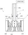
FIG. 1 is a schematic view of a plasma processing apparatus according to the present invention;
FIG. 2 is a schematic structural view of an air intake assembly according to the present invention;
fig. 3 is a schematic structural diagram of another air intake assembly provided by the present invention.
Detailed Description
The invention will be further described by the following specific examples in conjunction with the drawings, which are provided for illustration only and are not intended to limit the scope of the invention.
Referring to fig. 1, the present invention provides a plasma processing apparatus including: a gas inlet assembly 100, a reaction chamber 200, a susceptor 300, an electrostatic chuck 301, and an rf power source 400.
In the present embodiment, the gas inlet assembly 100 is disposed at the center of the top end of the reaction chamber 200 for supplying gas into the reaction chamber 200; the susceptor 300 is arranged at the bottom in the reaction chamber 200 and is used for bearing a substrate W to be processed; the electrostatic chuck 301 is arranged above the pedestal 300, and an electrode is embedded in the electrostatic chuck 301 and is used for applying current in the plasma etching process so as to clamp the substrate W to be processed; the rf power supply 400 is connected to the susceptor 300, and transmits the rf power supply to the interior of the reaction chamber 200 through the susceptor 300, and dissociates the gas in the interior of the reaction chamber 200 into plasma, which is used to perform plasma etching on the substrate W to be processed.
The plasma processing device further comprises an insulating window, a coil and a lining; wherein, the insulation window is located at the top of the reaction chamber 200, which has a through opening, and the gas inlet assembly 100 is located in the opening; the coil is positioned on the insulating window; the liner is carried over the sidewalls of the reaction chamber 200 and serves to protect the sidewalls of the reaction chamber 200.
In this embodiment, the plasma processing apparatus is an inductively coupled plasma processing apparatus, and in the plasma etching process, by adjusting the gas inlet assembly 100, an external gas source uniformly injects gas into the reaction chamber 200 through the gas inlet assembly 100 to adjust the gas distribution uniformity of the gas injected into the reaction chamber 200 by the gas inlet assembly 100, and then under the action of the radio frequency power source 400, the gas is dissociated into uniformly distributed plasma to etch the substrate W to be processed in the reaction chamber 200 of the plasma processing apparatus, so as to control the plasma etching distribution uniformity of the substrate W to be processed.
The above-described intake assembly 100 is explained in detail as follows:
fig. 2 is a schematic structural diagram of an air intake assembly according to the present invention.
Referring to fig. 2, the intake assembly 100 includes: a gas transmission member 1 and a movable member 2. Wherein, a main pipeline 103 is arranged in the gas transmission piece 1; the bottom of the gas transmission member 1 is provided with a first gas outlet channel 101 and a plurality of second gas outlet channels 102 surrounding the first gas outlet channel 101; the inner wall of the main pipeline 103 is provided with a plurality of first through holes 104 along the height thereof; the first through hole 104 is communicated with the second gas outlet channel 102, and the trunk pipeline 103 is communicated with the first gas outlet channel 101, so that the gas in the trunk pipeline 103 is respectively ejected out through the first gas outlet channel 101 and through the first through hole 104 and the second gas outlet channel 102.
The movable piece 2 is arranged in the main pipeline 103 and can move up and down along the inner wall of the main pipeline 103, the movable piece 2 is provided with a through second through hole 201, the second through hole 201 is communicated with an external gas source, and gas of the external gas source enters the main pipeline 103 in the gas transmission piece 1 through the second through hole 201 on the movable piece 2.
In the plasma etching process, an external gas source enters the main pipeline 103 through the second through hole 201 on the movable member 2, and moves up and down along the inner wall of the main pipeline 103 by adjusting the movable member 2 so as to seal or conduct the first through holes 104 at different heights on the inner wall of the main pipeline 103, so that the gas inside the main pipeline 103 is frequently switched to enter the corresponding second gas outlet channel 102 through the first through holes 104 at different heights, and is sprayed into the reaction cavity 200 of the plasma processing device. In the present embodiment, the movable member 2 having the second through hole 201 is a hollow piston.
In this embodiment, there are a plurality of first air outlet channels 101, all of which are disposed in the central region of the bottom end of the gas transmission member 1; the plurality of second air outlet channels 102 are uniformly distributed on the circumferences of different diameters of the bottom edge of the gas transmission member 1; by adjusting the movable part 2, the gas inside the main pipe 103 of the gas transmission part 1 is sprayed out from the first gas outlet pipe 101 at the center of the bottom end of the main pipe or is discharged from the first gas outlet pipe 101 and the second gas outlet pipe 102 together.
Wherein, the main pipeline 103 is communicated with the first air outlet channel 101, and the movable element 2 is adjusted in any state, and an external gas source can enter the main pipeline 103 through the second through hole 201 on the movable element 2, and is ejected through the main pipeline 103 at the center of the bottom end of the gas transmission element 1 and the first air outlet channel 101, so that the ejection stability of the external gas source is ensured.
In this embodiment, referring to fig. 2, a plurality of first through holes 104 sequentially downward along the height of the inner wall of the main pipe 103 are respectively and correspondingly communicated with second air outlet channels 102 whose diameters are sequentially reduced along the radial direction at the bottom end of the gas transmission member 1, so that when the movable member 2 is at a low position, the gas inside the main pipe 103 is only exhausted from the first air outlet channels 101 and the second air outlet channels 102 located on the circumference with the smallest diameter, and along with the upward movement of the movable member 2, the gas inside the main pipe 103 is exhausted from the first air outlet channels 101 and the second air outlet channels 102 located on the circumference with the sequentially increased diameters until the movable member 2 is located at the highest position, and the gas inside the main pipe 103 is exhausted from the first air outlet channels 101 and the second air outlet channels 102 located on the circumferences with all diameters at the same time.
That is, referring to fig. 2, the first through hole 104 located at the top end of the inner wall of the main conduit 103 is correspondingly communicated with the second air outlet channel 102 with the largest diameter along the radial direction at the bottom end of the gas transmission member 1; the first through hole 104 located at the bottom end of the inner wall of the main pipeline 103 is correspondingly communicated with the second air outlet channel 102 with the smallest radial diameter at the bottom end of the air transmission member 1, so that the air outlet range from the bottom of the air inlet assembly 1 is gradually increased in the process that the movable member 2 slowly moves upwards.
In embodiment 2, referring to fig. 3, a plurality of first through holes 104 which are sequentially downward along the height of the inner wall of the main pipe 103 are respectively and correspondingly communicated with second gas outlet channels 102 which are sequentially increased in diameter along the radial direction at the bottom end of the gas transmission member 1, so that when the movable member 2 is at a low position, the gas inside the main pipe 103 is only discharged from the first gas outlet channels 101 and the second gas outlet channels 102 which are positioned on the circumference with the largest diameter, and along with the upward movement of the movable member 2, the gas inside the main pipe 103 is discharged from the first gas outlet channels 101 and the second gas outlet channels 102 which are sequentially decreased in diameter on the circumference until the movable member 2 is positioned at the highest position, and the gas inside the main pipe 103 is discharged from the first gas outlet channels 101 and the second gas outlet channels 102 on the circumferences with all diameters at the same time.
That is, referring to fig. 3, the first through hole 104 located at the top end of the inner wall of the main conduit 103 is correspondingly communicated with the second air outlet channel 102 with the smallest diameter along the radial direction at the bottom end of the gas transmission member 1; the first through hole 104 located at the bottom end of the inner wall of the main pipeline 103 is correspondingly communicated with the second air outlet channel 102 with the largest radial diameter at the bottom end of the gas transmission member 1.
The corresponding communication relationship between the first through holes 104 and the second gas outlet channels 102 on different circumferences is not limited to that described in embodiments 1 and 2, and the gas channel design can be selected as required to achieve preferential gas outlet of the second gas outlet channels 102 on any diameter at the bottom end of the gas transmission member 1.
Referring to fig. 2, a plurality of first branch pipes 105 are further provided inside the gas transmission member 1; the first ends of the first branch pipelines 105 are respectively communicated with the first through holes 104 on the main pipeline 103, and the second ends of the first branch pipelines 105 are respectively communicated with the second air outlet channels 102, so that the gas inside the main pipeline 103 enters the second air outlet channels 102 through the through holes 104 with different heights on the inner wall of the main pipeline 103, and is ejected from the second air outlet channels 102 to enter the reaction cavity 200.
In the present embodiment, referring to fig. 2, the number of the first branch conduits 105 is the same as the number of the first through holes 104, and the first end of each first branch conduit 105 is correspondingly communicated with each first through hole 104 on the main conduit 103.
In this embodiment, referring to fig. 2, if the number of the first branch pipes 105 is the same as the number of the second gas outlet channels 102, the second end of each first branch pipe 105 is correspondingly communicated with each second gas outlet channel 102, so as to correspondingly communicate the first branch pipes 105 with the second gas outlet channels 102 one by one, and the exhaust opening and closing of the second gas outlet channel 102 corresponding to each first branch pipe 105 is controlled by controlling the opening and closing of the first through hole 104, so as to controllably adjust the uniformity of the gas outlet distribution at the bottom end of the gas transmission member 1.
In another embodiment, the number of first branch pipes 203 is different from the number of second outlet channels 102; the second end of every first branch pipe 203 still is provided with a plurality of second branch pipe, and every second branch pipe corresponds the intercommunication with every second gas outlet 202, with second branch pipe and second outlet channel 102 one-to-one intercommunication, guarantees that every first through-hole 104 and every first branch pipe 105 can control a plurality of second branch pipe who adjusts different positions to more meticulous regulation gas transmission spare 1 bottom is given vent to anger the homogeneity that distributes.
In the plasma etching process, an external gas source enters the main pipeline 103 through the second through hole 201 on the movable member 2, and moves downwards or upwards along the inner wall of the main pipeline 103 by adjusting the movable member 2 so as to seal or conduct the first through holes 104 on the inner wall of the main pipeline 103 at different heights, so that the gas of the gas source is regulated and controlled to be sprayed out only through the first gas outlet channel 101 of the gas transmission member 1 or sprayed out through the first gas outlet channel 101 and the second gas outlet channel 102 of the gas transmission member 1 together, and the uniformity of gas outlet distribution at the bottom end of the gas transmission member 1 is adjusted.
Referring to fig. 2 and 3, the movable member 2 is connected with the main conduit 103 in the gas transmission member 1 by a sealing member 3 in a sealing manner, so as to ensure gas tightness between the main conduit 103 and the movable member 2; in the present embodiment, the seal 3 is a gasket.
The working principle of the invention is as follows:
in the plasma etching process, an external gas source enters the main pipeline through a second through hole on a movable piece, the movable piece is adjusted to move downwards or upwards along the inner wall of the main pipeline so as to seal or conduct first through holes at different heights on the inner wall of the main pipeline, and gas in the main pipeline enters a second gas outlet channel through the first through hole, so that the gas of the gas source is regulated and controlled to be sprayed out only through the first gas outlet channel of the gas transmission piece or sprayed out together through the first gas outlet channel and the second gas outlet channel of the gas transmission piece, and the external gas source uniformly sprays gas into a reaction cavity of the plasma processing device through the gas inlet assembly; the radio frequency power supply dissociates the gas uniformly distributed from the gas inlet assembly to the inside of the reaction cavity into plasma through the base, and performs plasma etching on the substrate to be processed clamped by the electrostatic chuck, so as to control the uniformity of the plasma etching distribution of the substrate to be processed in the plasma processing device.
In summary, the gas inlet assembly and the plasma processing device thereof solve the problem that etching of a semiconductor structure is not uniform due to uneven gas outlet distribution of etching gas in the plasma etching process of the semiconductor structure, and the adjusting device is arranged in the gas inlet assembly, so that the uniformity of the gas outlet distribution of a gas source of the gas inlet assembly entering a reaction cavity is ensured, and the uniformity of etching in a plasma etching process is realized.
While the present invention has been described in detail with reference to the preferred embodiments, it should be understood that the above description should not be taken as limiting the invention. Various modifications and alterations to this invention will become apparent to those skilled in the art upon reading the foregoing description. Accordingly, the scope of the invention should be determined from the following claims.
Claims (12)
1. An air inlet assembly for a plasma processing apparatus, comprising:
the gas transmission piece is internally provided with a main pipeline, the bottom of the gas transmission piece is provided with a first gas outlet channel and a plurality of second gas outlet channels surrounding the first gas outlet channel, the inner wall of the main pipeline is provided with a plurality of first through holes along the height of the inner wall, the first through holes are communicated with the second gas outlet channels, and the main pipeline is communicated with the first gas outlet channels;
the movable piece is arranged in the main pipeline and can move up and down along the inner wall of the main pipeline, the movable piece is provided with a through second through hole, and the second through hole is connected with an external gas source so that gas from the gas source enters the main pipeline through the second through hole.
2. The gas inlet assembly for a plasma processing apparatus according to claim 1, wherein the plurality of second gas outlet channels are uniformly distributed on circumferences of different diameters of the bottom end edge of the gas delivery member; and the plurality of first through holes are sequentially downward along the height of the inner wall of the main pipeline and are respectively communicated with the second air outlet channels on different circumferences.
3. The gas inlet assembly for a plasma processing apparatus according to claim 2, wherein the plurality of first through holes sequentially downward along the height of the inner wall of the main conduit are respectively and correspondingly communicated with the second gas outlet channels on the circumference of which the bottom ends of the gas delivery members sequentially decrease in diameter along the radial direction.
4. The gas inlet assembly for a plasma processing apparatus as claimed in claim 2, wherein the plurality of first through holes sequentially downward along the height of the inner wall of the main conduit are respectively and correspondingly communicated with the second gas outlet channels, the diameters of which are sequentially increased along the radial direction, at the bottom end of the gas transmission member.
5. The gas inlet assembly for a plasma processing apparatus according to claim 1, wherein a plurality of first branch pipes are further disposed inside the gas delivery member, and first ends of the plurality of first branch pipes are respectively communicated with the plurality of first through holes; the second ends of the first branch pipelines are respectively communicated with the second air outlet channels.
6. The gas inlet assembly for a plasma processing apparatus according to claim 5, wherein a first end of one first branch conduit is in corresponding communication with one first through hole when the number of the first branch conduits is the same as the number of the first through holes.
7. The gas inlet assembly for a plasma processing apparatus as claimed in claim 5, wherein when the number of said first branch pipes is the same as the number of said second gas outlet channels, a second end of a first branch pipe is in communication with a corresponding one of said second gas outlet channels.
8. The gas inlet assembly for a plasma processing apparatus according to claim 5, wherein the number of the first branch pipes is different from the number of the second gas outlet channels; and the second end of each first branch pipeline is provided with a plurality of second branch pipelines, and each second branch pipeline is correspondingly communicated with each second air outlet channel.
9. The gas inlet assembly for a plasma processing apparatus as recited in claim 1, wherein said movable member is sealingly connected to said main conduit by a seal.
10. The gas inlet assembly for a plasma processing apparatus of claim 9, wherein the seal is a gasket.
11. A plasma processing apparatus, comprising:
the inner bottom of the reaction cavity is provided with a base for bearing a substrate to be processed;
a gas inlet assembly for a plasma processing apparatus as claimed in any of claims 1 to 10, for delivering gas into the reaction chamber.
12. The plasma processing apparatus as claimed in claim 11, further comprising:
the insulating window is positioned at the top of the reaction chamber and is provided with a through opening, and the air inlet assembly is positioned in the opening;
a coil positioned on the insulating window;
and the lining is carried above the side wall of the reaction cavity and is used for protecting the side wall of the reaction cavity.
Priority Applications (2)
| Application Number | Priority Date | Filing Date | Title |
|---|---|---|---|
| CN202010940995.5A CN114242551B (en) | 2020-09-09 | 2020-09-09 | Air inlet assembly and plasma processing device thereof |
| TW110129103A TWI834054B (en) | 2020-09-09 | 2021-08-06 | Air intake assembly and its plasma treatment device |
Applications Claiming Priority (1)
| Application Number | Priority Date | Filing Date | Title |
|---|---|---|---|
| CN202010940995.5A CN114242551B (en) | 2020-09-09 | 2020-09-09 | Air inlet assembly and plasma processing device thereof |
Publications (2)
| Publication Number | Publication Date |
|---|---|
| CN114242551A true CN114242551A (en) | 2022-03-25 |
| CN114242551B CN114242551B (en) | 2023-12-08 |
Family
ID=80742667
Family Applications (1)
| Application Number | Title | Priority Date | Filing Date |
|---|---|---|---|
| CN202010940995.5A Active CN114242551B (en) | 2020-09-09 | 2020-09-09 | Air inlet assembly and plasma processing device thereof |
Country Status (2)
| Country | Link |
|---|---|
| CN (1) | CN114242551B (en) |
| TW (1) | TWI834054B (en) |
Cited By (3)
| Publication number | Priority date | Publication date | Assignee | Title |
|---|---|---|---|---|
| CN118086876A (en) * | 2024-04-26 | 2024-05-28 | 上海谙邦半导体设备有限公司 | Adjustable gas delivery device and semiconductor processing equipment |
| CN118086877A (en) * | 2024-04-26 | 2024-05-28 | 上海谙邦半导体设备有限公司 | Adjustable air intake device and semiconductor processing equipment |
| CN119833380A (en) * | 2023-10-12 | 2025-04-15 | 江苏鲁汶仪器股份有限公司 | Jet structure and plasma etching machine |
Citations (6)
| Publication number | Priority date | Publication date | Assignee | Title |
|---|---|---|---|---|
| CN1846871A (en) * | 2005-12-09 | 2006-10-18 | 北京北方微电子基地设备工艺研究中心有限责任公司 | Single-admission and double-area adjustable nozzle |
| CN101138065A (en) * | 2005-03-07 | 2008-03-05 | 应用材料股份有限公司 | Gas baffles and diffusers for semiconductor processing chambers |
| CN102763199A (en) * | 2010-02-12 | 2012-10-31 | 应用材料公司 | Process chamber gas flow improvements |
| US20150167705A1 (en) * | 2013-12-17 | 2015-06-18 | Samsung Electronics Co., Ltd. | Substrate treating apparatus and blocker plate assembly |
| CN107112189A (en) * | 2014-12-30 | 2017-08-29 | 应用材料公司 | High Conductivity Handling Accessories |
| US20190085453A1 (en) * | 2017-09-19 | 2019-03-21 | Toshiba Memory Corporation | Film forming apparatus and film forming method |
Family Cites Families (5)
| Publication number | Priority date | Publication date | Assignee | Title |
|---|---|---|---|---|
| US20090071406A1 (en) * | 2007-09-19 | 2009-03-19 | Soo Young Choi | Cooled backing plate |
| WO2011159690A2 (en) * | 2010-06-15 | 2011-12-22 | Applied Materials, Inc. | Multiple precursor showerhead with by-pass ports |
| US10249511B2 (en) * | 2014-06-27 | 2019-04-02 | Lam Research Corporation | Ceramic showerhead including central gas injector for tunable convective-diffusive gas flow in semiconductor substrate processing apparatus |
| US9528184B2 (en) * | 2015-02-13 | 2016-12-27 | Eastman Kodak Company | Atomic-layer deposition method using compound gas jet |
| KR102636427B1 (en) * | 2018-02-20 | 2024-02-13 | 에이에스엠 아이피 홀딩 비.브이. | Substrate processing method and apparatus |
-
2020
- 2020-09-09 CN CN202010940995.5A patent/CN114242551B/en active Active
-
2021
- 2021-08-06 TW TW110129103A patent/TWI834054B/en active
Patent Citations (6)
| Publication number | Priority date | Publication date | Assignee | Title |
|---|---|---|---|---|
| CN101138065A (en) * | 2005-03-07 | 2008-03-05 | 应用材料股份有限公司 | Gas baffles and diffusers for semiconductor processing chambers |
| CN1846871A (en) * | 2005-12-09 | 2006-10-18 | 北京北方微电子基地设备工艺研究中心有限责任公司 | Single-admission and double-area adjustable nozzle |
| CN102763199A (en) * | 2010-02-12 | 2012-10-31 | 应用材料公司 | Process chamber gas flow improvements |
| US20150167705A1 (en) * | 2013-12-17 | 2015-06-18 | Samsung Electronics Co., Ltd. | Substrate treating apparatus and blocker plate assembly |
| CN107112189A (en) * | 2014-12-30 | 2017-08-29 | 应用材料公司 | High Conductivity Handling Accessories |
| US20190085453A1 (en) * | 2017-09-19 | 2019-03-21 | Toshiba Memory Corporation | Film forming apparatus and film forming method |
Cited By (6)
| Publication number | Priority date | Publication date | Assignee | Title |
|---|---|---|---|---|
| CN119833380A (en) * | 2023-10-12 | 2025-04-15 | 江苏鲁汶仪器股份有限公司 | Jet structure and plasma etching machine |
| CN119833380B (en) * | 2023-10-12 | 2026-06-26 | 江苏鲁汶仪器股份有限公司 | A jet structure and plasma etching machine |
| CN118086876A (en) * | 2024-04-26 | 2024-05-28 | 上海谙邦半导体设备有限公司 | Adjustable gas delivery device and semiconductor processing equipment |
| CN118086877A (en) * | 2024-04-26 | 2024-05-28 | 上海谙邦半导体设备有限公司 | Adjustable air intake device and semiconductor processing equipment |
| CN118086876B (en) * | 2024-04-26 | 2024-08-06 | 上海谙邦半导体设备有限公司 | Adjustable gas delivery device and semiconductor processing equipment |
| CN118086877B (en) * | 2024-04-26 | 2024-08-20 | 上海谙邦半导体设备有限公司 | Air inlet adjustable device and semiconductor processing equipment |
Also Published As
| Publication number | Publication date |
|---|---|
| TWI834054B (en) | 2024-03-01 |
| CN114242551B (en) | 2023-12-08 |
| TW202230433A (en) | 2022-08-01 |
Similar Documents
| Publication | Publication Date | Title |
|---|---|---|
| KR100954709B1 (en) | Adjustable multi-zone gas injection system | |
| KR102263328B1 (en) | Chemical deposition chamber having gas seal | |
| US5338363A (en) | Chemical vapor deposition method, and chemical vapor deposition treatment system and chemical vapor deposition apparatus therefor | |
| CN102763199B (en) | The air-flow improvement for the treatment of chamber | |
| US9536710B2 (en) | Tunable gas delivery assembly with internal diffuser and angular injection | |
| CN114242551B (en) | Air inlet assembly and plasma processing device thereof | |
| TWI800497B (en) | Chemical deposition chamber having gas seal | |
| US20090221149A1 (en) | Multiple port gas injection system utilized in a semiconductor processing system | |
| KR20150108344A (en) | Inductively-coupled plasma reactor for plasma uniformity and efficiency enhancement and method for manufacturing semiconductor substrate using the device | |
| KR20020060970A (en) | Plasma processing system with dynamic gas distribution control | |
| KR100984121B1 (en) | Apparatus for and method of treating substrate by plasma | |
| CN202616186U (en) | Inductive coupling plasma etching chamber | |
| CN115613009A (en) | Atomic Layer Deposition Equipment | |
| US11004703B1 (en) | Gas flow guiding device for semiconductor processing apparatus and method of using the same | |
| CN217719496U (en) | Wafer temperature control system and plasma processing device | |
| CN102395243A (en) | Inductance coupling plasma device for improving uniformity and efficiency of plasmon | |
| WO2024139768A1 (en) | Gas conveying device and system, and plasma processing device | |
| CN114203511B (en) | Upper electrode assembly and semiconductor process equipment | |
| KR20120094291A (en) | Plasma generating unit, and apparatus for treating substrate using plasma | |
| KR20100083917A (en) | Gas supply system for plasma etching apparatus | |
| KR100716690B1 (en) | Apparatus and method for processing semiconductor piece | |
| KR20010104572A (en) | A chemical vapor deposition apparatus | |
| CN119381235B (en) | Gas distributor, plasma processing apparatus, and gas switching operation method | |
| CN101150039A (en) | Gas injection device | |
| KR101629213B1 (en) | Apparatus and method of processing substrate |
Legal Events
| Date | Code | Title | Description |
|---|---|---|---|
| PB01 | Publication | ||
| PB01 | Publication | ||
| SE01 | Entry into force of request for substantive examination | ||
| SE01 | Entry into force of request for substantive examination | ||
| GR01 | Patent grant | ||
| GR01 | Patent grant |