The disclosures in italian patent application No. 102020000022564, filed 24/9/2020, from which this patent application claims priority, are incorporated herein by reference in their entirety.
Detailed Description
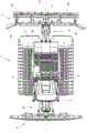
Referring to fig. 1-3, a snow groomer according to an embodiment of the present invention is generally indicated by reference numeral 1 and includes a frame 2 extending along a longitudinal axis 70, a cab 3, a drive unit 5 (e.g., an internal combustion engine). The cab 3 and the drive unit 5 are accommodated on the frame 2. The snow groomer 1 is also provided with a pair of tracks 6, and user devices, including a bucket or blade 8 supported at the front by the frame 2 and a snow plow assembly 9 supported at the rear by the frame 2, having a snow plow 9a and preferably a trimmer 9 b. There may also be a winch assembly not shown here.
The drive unit 5 provides the power required for the operation of the snow groomer 1 and in particular the tracks 6 and the user devices 8 and 9.
The transmission 12 may be hydraulic or electronic or a combination thereof.
The drive unit 5 may be an electric motor having a rechargeable battery instead of the internal combustion engine. Alternatively, the drive unit 5 may be a hybrid engine comprising an internal combustion engine and an electric motor connected in series or in parallel. In another embodiment, the drive unit 5 may be a hydrogen-powered fuel cell engine.
The snow plow 9a includes, among other things, a toothed rotating shaft 9d and a shroud 9c disposed above the rotating shaft 9 d. The region between the shield 9c and the rotation shaft 9d is designated as a working chamber and is configured to have a variable volume. In particular, the snow plow 9a includes a device for changing the distance between the rotary shaft 9d and the shroud 9c or for changing the position of the dresser 9b, so that the volume of the working chamber can be adjusted. The device may be acted on by changing the position of the rotary shaft 9d or may be acted on by adjusting the position of the shroud 9c or may be acted on by changing the position of the dresser 9 b. By changing the working chamber, different plowing of the treated snow layer can be performed.
The snow plow assembly 9 includes two side vanes 9e disposed transversely with respect to the shroud 9 c.
In one embodiment, not shown in the drawings, the snow plow assembly 9 includes two snow plows 9a connected to each other by a preferably universal joint. In this embodiment, the two snow plows 9a each include a toothed rotating shaft 9d and a shroud 9c disposed above the rotating shaft 9 d.
A user interface is mounted in the cab 3 that allows the operator to control the movement of the snowmobile 1 and the operation of the user devices.
In particular, the snow blower 1 comprises a user interface, which in turn comprises a travel controller 10 of the movement of the snow blower 1 for controlling the direction and speed of travel of the snow blower 1, in particular the travel controller 10 controls the movement of the tracks 6, thus defining the direction and speed of movement of the snow blower 1.
Furthermore, the snow groomer 1 comprises a user interface which in turn comprises an activation commander 11 for operating the user device, which activation commander 11 particularly controls the user device. In one embodiment, the start commander 11 comprises a joystick having a control stick, a plurality of buttons. In one embodiment, the joystick comprises at least one slider and at least one mini-stick.
In particular, the start commander 11 controls one or more of the following parameters associated with the snow plow assembly 9: the rotational speed and/or direction of rotation of the shaft 9 d; the depth and/or cutting angle of the snow plow assembly 9, preferably the snow plow 9 a; the location of the snow plow assembly 9a along the vertical axis 71; the modes for adjusting the position of the snow plow assembly 9 along the vertical axis 71 preferably include: a mode in which the snow plow assembly 9 is in a fixed position, a mode in which the snow plow assembly 9 exerts a certain pressure on the snow layer 72 in addition to its own weight or subtracts its own weight and the value of the applied pressure, and a mode in which the snow plow assembly 9 is in a floating position, in particular in a floating position in which it follows the snow layer 72; the position where the flap 9e is open or closed; the volume of the working chamber of the snow plow 9 a; the position of the snow plow 9a relative to the horizontal plane 73; a mode of adjusting the position of the snow plow 9a with respect to the horizontal plane 73, preferably between a mode in which the snow plow assembly 9 is in a fixed position and a mode in which the snow plow assembly is in a floating position, in particular in a floating position in which it follows the movement of the snow horn 1; and the position of the dresser 9 b.
Furthermore, in the above-described embodiment in which the snow plough assembly 9 comprises two snow ploughs 9a connected to each other by means of a preferably universal joint, in addition to what has been described above, the activation commander 11 can also control, among one or more of the above-described combinations of parameters, the mode of adjusting the relative position of the two snow ploughs 9a in the snow plough assembly 9, in particular comprising: the relative position of the two snow plows 9a is free and thus the two snow plows 9a are freely movable independently of each other, a mode in which the positions of the two snow plows 9a are fixed such that the two snow plows 9a form a specified angle of 180 ° in a plane inclined with respect to the snow layer 72 (specifically, the angle is toward the snow layer 72), a mode in which the positions of the two snow plows 9a are fixed such that the two snow plows 9a form a specified angle of less than 180 ° in a plane inclined with respect to the snow layer 72 (specifically, the angle is toward the snow layer 72), and a mode in which the positions of the two snow plows 9a are fixed such that the two snow plows 9a form a specified angle of more than 180 ° in a plane inclined with respect to the snow layer 72 (specifically, the angle is toward the snow layer 72).
In addition, the start commander 11 controls the position of the blade 8 with respect to the three cartesian coordinate axes.
In one non-limiting embodiment, the snow blower 1 includes a user interface that in turn includes a display screen 4 configured to display information related to the operating parameters of the snow blower 1 and the user devices (particularly the blade 8 and the snow plow assembly 9).
The snow groomer 1 is provided with a satellite navigation device 13 and a control system 15.
The Satellite Navigation device 13 is, for example, a GNSS ("Global Navigation Satellite System"), which is configured to determine its three-dimensional position and orientation with centimeter-level accuracy and thus the three-dimensional position and orientation of the snow sled 1. In fact, in addition to the direction of travel, the satellite navigation device 13 is able to determine the longitude LG, the latitude LT and preferably the altitude H from the ground. The height H from the ground corresponds to the thickness of the snow deposit 72 at the coordinates of the satellite navigation device 13 and of the snow groomer 1. In particular, the height H from the ground may be determined by the difference between the height detected by the satellite navigation device 13 and the ground height defined by a reference map with corresponding longitudes LG and lat LT. The reference map may be made using satellite navigation device 13 without snow and stored in satellite navigation device 13 or control system 15. In the first case, the height H from the ground is provided directly by the satellite navigation device 13; in the second case, the satellite navigation device 13 may provide an altitude relative to a reference altitude (e.g. sea level) and the altitude H from the ground is determined by the control system 15 using the reference map.
The control system 15 detects operating parameters of the snow roller 1, such as, but not exclusively: the power supplied by the drive unit 5; the power absorbed by each user device, in particular the blade 8 and the snow plow 9; the location of the blade 8 and snow plow assembly 9; and the traveling speed of the snow thrower 1.
In addition, the control system 15 can detect one or more operating parameters of the snow plow 1 selected from the following operating parameters of the snow plow assembly 9: the rotational speed and/or direction of rotation of the shaft 9 d; the depth and/or cutting angle of the snow plow assembly 9, preferably the snow plow 9 a; the location of the snow plow assembly 9a along the vertical axis 71; modes for adjusting the position of the snow plow assembly 9 along the vertical axis 71 preferably include a mode in which the snow plow assembly 9 is in a fixed position, a mode in which the snow plow assembly 9 exerts a certain pressure on the snow layer 72 in addition to its own weight or subtracts the value of the applied pressure from its own weight, and a mode in which the snow plow assembly 9 is in a floating position, particularly in a floating position in which it follows the snow layer 72; the position where the flap 9e is open or closed; the volume of the working chamber of the snow plow 9 a; the position of the snow plow 9a relative to the horizontal plane 73; a mode of adjusting the position of the snow plow 9a with respect to the horizontal plane 73, preferably between a mode in which the snow plow assembly 9 is in a fixed position and a mode in which the snow plow assembly is in a floating position, in particular in a floating position in which it follows the movement of the snow horn 1; and the position of the dresser 9 b.
Furthermore, in the above-described embodiment in which the snow plough assembly 9 comprises two snow ploughs 9a connected to each other by means of a preferably universal joint, in addition to what has been described above, the control system 15 can also detect, among one or more of the operating parameters of the above-described combination of parameters, an adjustment mode of the relative position of the two snow ploughs 9a in the snow plough assembly 9, in particular comprising: the relative position of the two snow plows 9a is free and thus the two snow plows 9a are freely movable independently of each other, a mode in which the positions of the two snow plows 9a are fixed such that the two snow plows 9a form a specified angle of 180 ° in a plane inclined with respect to the snow layer 72 (specifically, the angle is toward the snow layer 72), a mode in which the positions of the two snow plows 9a are fixed such that the two snow plows 9a form an angle of less than 180 ° in a plane inclined with respect to the snow layer 72 (specifically, the angle is toward the snow layer 72), and a mode in which the positions of the two snow plows 9a are fixed such that the two snow plows 9a form an angle of more than 180 ° in a plane inclined with respect to the snow layer 72 (specifically, the angle is toward the snow layer 72).
The control system 15 is equipped with wireless connection capabilities, for example, directly by means of a local communication network or by means of a mobile data network and an internet connection, for connecting to a resource management system of a ski field not shown here.
In particular, the snow groomer 1 comprises a radio wave communication unit 18 coupled to the control system 15 for transmitting remotely received information to the control system 15 or transmitting information from the control system 15 to the outside.
The blade 8 is connected to the frame 2 by a forward attachment 20, while the snow plow assembly 9 is connected to the frame 2 by a rearward attachment 21.
An activation commander 11 configured to control the front attachment 20 is housed in the cab 3 and allows control of the position of the blade 8.
In addition, the start commander 11 is configured to control the rear attachment 21 and is accommodated in the cab 3.
Referring to fig. 1 and 2, the rear attachment 21 also includes an actuator assembly 50 (fig. 2) for controlling one or more of the following parameters of the snow plow assembly 9: the rotational speed and/or direction of rotation of the shaft 9 d; the depth and/or cutting angle of the snow plow assembly 9, preferably the snow plow 9 a; the location of the snow plow assembly 9a along the vertical axis 71; modes for adjusting the position of the snow plow assembly 9 along the vertical axis 71 preferably include a mode in which the snow plow assembly 9 is in a fixed position, a mode in which the snow plow assembly 9 exerts a certain pressure on the snow layer 72 in addition to its own weight or subtracts its own weight and the value of the applied pressure, and a mode in which the snow plow assembly 9 is in a floating position, in particular in a floating position in which it follows the snow layer 72; the position where the flap 9e is open or closed; the volume of the working chamber of the snow plow 9 a; the position of the snow plow 9a relative to the horizontal plane 73; a mode of adjusting the position of the snow plow 9a with respect to the horizontal plane 73, preferably between a mode in which the snow plow assembly 9 is in a fixed position and a mode in which the snow plow assembly is in a floating position, in particular in a floating position in which it follows the movement of the snow horn 1; and the position of the dresser 9 b.
Furthermore, in the above-described embodiment in which the snow plow assembly 9 includes two snow plows 9a connected to each other by a preferably universal joint, in addition to the above, the actuator assembly 50 (FIG. 2) may also control the mode of adjusting the relative position of the two snow plows 9a in the snow plow assembly 9 in one or more of the following combinations of parameters described above, preferably including: the relative position of the two snow plows 9a is free and thus the two snow plows 9a are freely movable independently of each other, a mode in which the positions of the two snow plows 9a are fixed such that the two snow plows 9a form a specified angle of 180 ° in a plane inclined with respect to the snow layer 72 (specifically, the angle is toward the snow layer 72), a mode in which the positions of the two snow plows 9a are fixed such that the two snow plows 9a form an angle of less than 180 ° in a plane inclined with respect to the snow layer 72 (specifically, the angle is toward the snow layer 72), and a mode in which the positions of the two snow plows 9a are fixed such that the two snow plows 9a form an angle of more than 180 ° in a plane inclined with respect to the snow layer 72 (specifically, the angle is toward the snow layer 72).
The start commander 11 is configured to control the rear linkage 21 and the actuator assembly 50 of the snow plow assembly 9. The start commander 11 is housed in the cab 3 and allows to adjust one or more of the operating parameters mentioned above.
In one embodiment, the activation commander 11 for controlling the blade 8, in particular the front linkage 20, and the activation commander 11 for controlling the snow plow assembly 9, in particular the actuator assembly 50 and the rear linkage 21 of the snow plow assembly 9, are generally defined by a single manual control device, which is a joystick having a control lever and a series of mini-levers and buttons located on the control lever.
The control system 15 includes a control device 17 coupled to the snow plow assembly 9 and configured to control at least two parameters a and B, preferably five parameters A, B, C, D and E, of the snow plow assembly 9 selected from the group consisting of the following parameters of the snow plow assembly 9: the rotational speed and/or direction of rotation of the shaft 9 d; the depth and/or cutting angle of the snow plow assembly 9, preferably the snow plow 9 a; the location of the snow plow assembly 9a along the vertical axis 71; modes for adjusting the position of the snow plow assembly 9 along the vertical axis 71 preferably include a mode in which the snow plow assembly 9 is in a fixed position, a mode in which the snow plow assembly 9 exerts a certain pressure on the snow layer 72 in addition to its own weight or subtracts its own weight and the value of the applied pressure, and a mode in which the snow plow assembly 9 is in a floating position, in particular in a floating position in which it follows the snow layer 72; the position where the flap 9e is open or closed; the volume of the working chamber of the snow plow 9 a; the position of the snow plow 9a relative to the horizontal plane 73; a mode of adjusting the position of the snow plow 9a with respect to the horizontal plane 73, preferably between a mode in which the snow plow assembly 9 is in a fixed position and a mode in which the snow plow assembly is in a floating position, in particular in a floating position in which it follows the movement of the snow horn 1; and the position of the dresser 9 b.
Furthermore, in the above-described embodiment in which the snow plow assembly 9 comprises two snow plows 9a connected to each other by a preferably universal joint, in addition to the above, the control device 17 coupled to the snow plow assembly 9 can control at least two parameters a and B, in particular at least five parameters A, B, C, D and E, of the snow plow assembly 9 selected from the above-described combination of parameters, which additionally comprises a mode of adjusting the relative position of the two snow plows 9a in the snow plow assembly 9, preferably comprising: a mode in which the relative positions of the two snow plows are free and thus the two snow plows can move freely independently of each other; the positions of the two snow plows 9a are fixed in a mode such that the two snow plows 9a form a specified angle of 180 ° in a plane inclined with respect to the snow layer 72 (in particular, the angle is toward the snow layer 72); the position of the two snow plows is fixed in a mode such that the two snow plows 9a form an angle of less than 180 ° in a plane inclined with respect to the snow layer 72 (in particular, the angle is toward the snow layer 72); and a mode in which the positions of the two snow plows 9a are fixed such that the two snow plows 9a form an angle greater than 180 deg. in a plane inclined with respect to the snow layer 72 (specifically, the angle is toward the snow layer 72).
In addition, the control device 17 comprises a memory 19 configured to store at least two sets of values N and M, preferably four sets of values N, M, P, Q, associated with at least two parameters a and B, wherein each set of values comprises at least one value for each of the at least two parameters a and B.
In a preferred embodiment, value sets N, M each include a first value N ', M' and a second value N ", M" for each of at least two parameters A and B. The first values N ', M' are associated with the upward movement of the snow roller 1 and the second values N ", M" are associated with the downward movement of the snow roller 1.
The control device 17 is designed to receive the result of the selection of a value group of at least two value groups N, M, preferably four value groups N, M, P, Q, and to determine the value N of the selected value group from the values NAAnd NBOr MAAnd MBTo control at least two parameters a and B of the snow plow assembly.
Furthermore, the control device 15 is configured to receive information relating to the upward movement of the snowmobile 1 or the downward movement of the snowmobile 1 and to control the at least two parameters by using the first N ', M' or the second N ", M" values for each set of values of the at least two parameters according to the received information relating to the upward or downward movement of the snowmobile.
In more detail, the selection among the numerical groups N and M or N, M, P and Q and among the first numerical value N '(or M', P 'and Q') and the second numerical value N "(or M", P "and Q") can be made in various ways.
In one embodiment, the selection among the set of values is made by a user interface, which in particular comprises a selection commander 39 for receiving the selection result from the operator. The selection commander 39 may be a key or a series of keys, or may be a touch sensitive device of a touch screen on which different combinations of selectable numerical values are displayed. In other words, in this embodiment, the operator manually selects the set of values that he/she wishes to use by the selection commander 39 of the snowmobile 1 among the two sets of values N and M (or the four sets of values N, M, P and Q).
Preferably, each of the two sets of values N and M (or the four sets of values N, M, P and Q) is associated with a respective snow situation that is different from one another, such as fresh snow, spring snow, solid snow, or a customizable outline. The operator can thus see the value sets associated with these different snow conditions on the user interface, in particular on the screen, and select the current snow condition and thus the parameter value combination to be used, either by pressing a button or directly on the screen (in the case of a touch screen).
In addition, the operator can send information about the downward or upward movement of the snowmobile 1 to the control device 17 via the user interface and thus select whether to use the first value of the selected value set of the parameter A, B (or A, B, C, D, E) or the second value of the selected value set of the parameter A, B (or A, B, C, D, E).
In an alternative embodiment, the control device 17 is configured to control any number of more than two parameters A, B, C … … of the snow plow assembly 9 selected from the above-described combination of parameters.
In an alternative embodiment, the user may select the number and type of parameters A, B, C … … to be controlled in the automatic mode at any time through the user interface.
In an alternative embodiment, the memory 19 of the control device 17 is configured to store two or more of any number of value sets associated with two or more of any number of parameters, wherein each value set comprises at least one value, preferably two values, for each parameter.
As described above, the selection of the first value X 'or the second value X' of value set N, M, P, Q and value set N, M, P, Q can be performed manually through a user interface and preferably through selection of commander 39, or can be performed automatically as described below, or a combination of manually and automatically.
In a preferred embodiment, the snowmobile 1 includes a detection unit 40 for detecting the upward or downward movement of the snowmobile 1 communicatively connected to the control device 17 and sending information related to the upward or downward movement of the snowmobile 1 to the control device 17, and wherein the control device 17 controls the at least two parameters by selecting the first value X' or the second value X "for each value set N, M, P, Q of the at least two parameters A, B based on the information related to the upward or downward movement of the snowmobile 1 received from the detection device 40.
In a preferred embodiment, the detection means 40 comprise an inclinometer and/or satellite tracking means 13.
In a preferred embodiment, the snow groomer 1 comprises detection means 41 for detecting a snow situation, which are communicatively coupled with the control means 17 to transmit information about the snow situation, so that the control means 17 select one of the two value sets on the basis of the detected snow situation. Thus, in this case, the selection of the snow situation is made automatically and without operator intervention.
In a preferred embodiment, the detection means 41 for detecting the snow accumulation comprise at least one means chosen from the following group of means: a snow temperature sensor; an ambient temperature sensor; a snow water content sensor; an ambient humidity sensor; a snow density sensor; an ambient light level sensor; a camera for photographing the snow-accumulated surface; thermal imaging camera for shooting snow surface.
In a preferred embodiment, the snow groomer 1 comprises a radio frequency communication unit 18 configured to receive data associated with weather conditions and/or the current date. The communication unit 18 is communicatively coupled to the control device 17 to transmit information relating to weather conditions and/or the current date. Control device 17 receives information relating to weather conditions and/or the current date and selects one of two value sets N or M (or one of four value sets N, M, P or Q) based on the received weather conditions and/or the current date.
In a preferred embodiment, the control device 17 is configured to receive at least one datum relating to the snow situation remotely via the communication unit 18, for example, and the operator of the ski field can remotely transmit the datum relating to the snow situation and/or which set of values to use among the two sets of values N and M or the four sets of values N, M, P and Q. In this case, control device 17 is configured to select one of two value sets N, M (or four value sets N, M, P and Q) based on data received from a remote location.
In a preferred embodiment, control device 17 includes a counting unit 42 for calculating a date, and control device 17 selects one of sets of values N, M based on the date provided by date counting unit 42.
In a preferred embodiment, the user interface is coupled to the control device 17 and is configured to receive a selection result relating to the snow situation.
In particular, FIG. 6 shows an exemplary display screen 4 of a preferred embodiment on which selectable snow conditions 100 are displayed. In particular, in the non-limiting example shown in fig. 6, the following is shown: fresh snow, spring snow, dense snow, or customizable contours.
As described above, each snow event 100 is associated with a respective set of values N, M, P, Q.
Via the display 4, the operator selects what snow situation he/she considers to be the most appropriate and thus which of the sets of values to use.
In addition, fig. 6 depicts a display screen 4 showing the values of the selected value group and a parameter A, B, C, D, E that can be controlled in an automated manner.
In addition, the display 4 in fig. 6 also shows two different values of the parameter A, B, C, D, E when the snowmobile 1 is moving up and when it is moving down. In this case, the display screen 4 indicates whether an automatic mode of detecting the upward or downward movement of the snow blower 1 is activated or whether the upward or downward movement mode has been selected by the operator.
Furthermore, the display screen is configured to represent an optimal speed value 101 associated with the value of the parameter currently used and/or an optimal suspension setting value 102 associated with the value of the parameter currently used. Preferably, the display screen 4 is also configured to display the current advancing speed 103 of the snow roller 1 in the same screen shot.
In this manner, the operator can adjust the speed of the snowmobile 1 to move at an optimal speed and/or set suspension parameters to optimal values by activating the travel control 10.
In a preferred embodiment, the display screen 4 is a touch screen, i.e. a touch sensitive screen, so the operator can directly select one or more of the following options on the display screen 4 by touching the display screen 4: snow accumulation; an automatic mode that detects upward or downward movement; detecting a manual mode of upward or downward movement; selecting whether to use an up or down motion value; and changing the value of each set of values. In this embodiment, the selection commander 39 is preferably defined by a touch screen of the display screen 4.
In all embodiments, the control device 17 receives information about the snow situation and selects one of the sets of values N, M (N, M, P, Q) based on the received selection result of the snow situation.
Further, in a preferred embodiment, the plurality of sets of values includes an additional set of values associated with the artificial snow. Thus, there will be three or five or a number of sets equal to or greater than three. In this embodiment, the set of values comprising the parameters suitable for treating the artificial snow can be selected manually by the operator or, in a preferred embodiment, in an automatic or semi-automatic manner. In one embodiment, the snow groomer 1 is coupled to a device for producing artificial snow or to a ski field management system, which in turn is coupled to a device for producing artificial snow. In this preferred embodiment, when the automatic mode is selected, the control device 17 is configured to use the third (or fifth) set of values associated with the artificial snow when it receives information, either remotely by the artificial snow generating device or by a coupled ski field.
In addition, each value of the set of values can be changed by the operator by means of a user interface (for example, selecting the commander or activating the commander 11), but only in the case where the snow-pressing vehicle 1 is stationary. For this purpose, the control device 17 is configured to receive, by the operator, a modification of the values in each set of values of the parameter and to change each value in the set of values of the parameter. Furthermore, the control system 15 enables the control device 17 to change the parameters only when it detects that the snow roller 1 is stationary and has placed the snow roller 1 in a mode of locking the tracks and the user device.
Further, the start commander 11 is always started and operated during the operation of the snow blower 1, and therefore, during the operation, the operator can operate the parameters to change the parameters currently set in the automatic mode. In this case, the snow groomer 1 that has changed the parameter will no longer use automatic adjustment, but will follow the manual adjustment set by the operator until the snow groomer 1 is turned off or until the operator enters an automatic mode for the parameter as well via the user interface.
In a preferred embodiment, in the manual mode, in which the operator manually sets the values of the set of values to be used through the user interface, the control device 17 stores the values of the set of values set by the operator during its operation and associates them with the other detected parameters (for example weather, snow temperature, ambient temperature, snow density, snow water content, brightness, inclination, position of the snow groomer 1 in the ski field) and defines the coupling between the values of the set of values selected by the operator and the detected parameters. In a preferred embodiment, the control means 17 are configured to operate in automatic mode using the values of the set of values coupled with the parameters that have been previously coupled and stored.
In other words, the user interface 4 is configured to allow an operator to set each of at least one value of the at least two sets of values of the at least one parameter. Furthermore, the control device 17 is configured to record, in an operating mode, at least one numerical value entered by the operator via the user interface and to associate it with one or more of the following detected parameters: the location of the snow compactor, the temperature and/or humidity of the air and/or snow, the received weather data. The control device 17 is configured to set, in a further operating mode, at least one value of each value set in the first operating mode on the basis of the data recorded in the first operating mode and the detected one or more of the following parameters: the location of the snow compactor, the temperature and/or humidity of the air and/or snow, the received weather data.
In one embodiment, the control device 17 stores the parameters used by the operator in manual mode and transmits them to a remote central unit of the ski field, which analyzes the data and defines the parameter values of the set of values. In the semi-automatic mode, the operator may autonomously select one of the sets of values N, M, P, Q and the control device 17 couples them to the detected data, temperature, humidity, etc. and uses them in the fully automatic mode.
In a preferred embodiment, the present invention includes a snowboarding fleet having more than two snowboarding trucks.
Each of the snow mobiles 1 is configured to exchange data through the communication unit 18, and the control device 17 is configured to send the selection result of the set of values to be used at the designated position of the runway to the other snow mobile(s) 1. The other snowmobile(s) are configured to receive a selection of the set of values and display the selection on a screen to send information to the operator. By means of the selection means, the operator can choose whether to use the set of values received from a remote location or which he/she has set in advance on his/her snow mobiles 1. In an alternative embodiment, each control device 17 controls the parameters of the snow plow assembly based on the selected set of values it receives.
In a preferred embodiment, the ski field comprises a remote central unit. In manual mode and automatic or semi-automatic mode, each of the snow mobiles 1 sends data to a remote central unit of the ski field that analyzes the data of each of the snow mobiles 1 in the fleet of snow mobiles 1.
In more detail, each control device 17 stores the values of the set of values chosen by the operator during its use and associates them with the other parameters detected (for example weather, snow temperature, ambient temperature, snow density, snow water content, brightness, inclination, position within the ski field provided by the satellite tracking device 13). Each control device defines the coupling between the values of the set of values selected by the operator and the detected parameters and transmits them to the remote central unit. The remote central unit analyzes the data received from the plurality of control devices and processes these data, for example by using statistical functions (e.g. mean, median, variance) and defines the values of the set of values to be used in the automatic mode.
In a preferred embodiment, the control device 17 is configured to operate in an automatic mode using the values of the set of values coupled with the parameters it was previously coupled with and stored.
In a preferred embodiment, the snow groomer 1 is configured to be activated by a user code. The control means 7 store at least the first user code and the second user code in a memory. The control device 7 is configured to detect a user code entered by the operator through the user interface when starting the snow groomer 1 and to transmit or not transmit data to other snow groomers 1 based on the user code entered between the first user code and the second user code.
In a preferred embodiment, the snow groomer 1 is configured to be activated by a user code. The control means 17 store at least the third user code and the fourth user code in a memory. The control device 7 is configured to detect a user code entered by the operator via the user interface when starting the snow groomer 1 and to change or not change the value of the value set of the control device.
In a preferred embodiment, the snow groomer 1 is configured to be activated by a user code. The control means 17 store at least the fifth user code and the sixth user code in a memory. The control device 17 is configured to detect a user code entered by the operator via the user interface and to select between or not manual, automatic or semiautomatic control when starting the snow groomer 1, in other words, based on the entered user code, the control device 17 can use only manual control or can use only automatic and/or semiautomatic control or can use all control modes.
It will be understood from this description that the invention may be extended to any number of parameters greater than or equal to two, for example, in fig. 5 the invention is represented using five parameters A, B, C, D and E, but the number of parameters may be two, i.e. A, B, or six, i.e. A, B, C, D, E and F, or any number greater than one. Increasing the number of parameters increases the automation efficiency of the snow blower 1 and therefore the ease with which the driver can drive the snow blower.
Multiple value sets N, M, … …, Z can be any number greater than or equal to two, and what has been described above for two value sets or four value sets applies to any number of value sets greater than or equal to two.
In a preferred embodiment, the control means 17 comprise any number greater than two of the user codes selected from the user codes mentioned above, and therefore it may comprise six user codes mentioned above or four user codes mentioned above or a combination of user codes with the functions mentioned above.
In a preferred, non-limiting embodiment of the invention, the snow plow assembly 9 of the snow blower 1 comprises two snow plows 9a connected to each other by a preferably universal joint, and the parameters controlled by the control device 17 according to the modes described above are the following parameters: the rotational speed and/or direction of rotation of the shaft 9 d; the depth or cutting angle of the snow plow assembly 9, preferably the snow plow 9 a; the modes for adjusting the position of the snow plow assembly 9 along the vertical axis preferably include: a mode in which the snow plow assembly 9 is in a fixed position, a mode in which the snow plow assembly 9 exerts a certain pressure on the snow layer 72 in addition to its own weight or subtracts its own weight and the value of the applied pressure, and a mode in which the snow plow assembly 9 is in a floating position, in particular in a floating position in which it follows the snow layer 72; the volume of the working chamber of the snow plow 9 a; the mode of adjusting the relative position of the two snow plows 9a in the snow plow assembly 9 preferably includes: the relative position of the two snow plows 9a is free and thus the two snow plows 9a are freely movable independently of each other, a mode in which the positions of the two snow plows 9a are fixed such that the two snow plows 9a form a specified angle of 180 ° in a plane inclined with respect to the snow layer 72 (specifically, the angle is toward the snow layer 72), a mode in which the positions of the two snow plows are fixed such that the two snow plows 9a form a specified angle of less than 180 ° in a plane inclined with respect to the snow layer 72 (specifically, the angle is toward the snow layer 72), and a mode in which the positions of the two snow plows 9a are fixed such that the two snow plows 9a form a specified angle of more than 180 ° in a plane inclined with respect to the snow layer 72 (specifically, the angle is toward the snow layer 72).
In another preferred, non-limiting embodiment of the invention, the snow plow assembly 9 of the snow blower 1 comprises two snow plows 9a connected to each other by a preferably universal joint, and the parameters controlled by the control device 17 according to the modes described above are the following parameters: the rotational speed and/or direction of rotation of the shaft 9 d; preferably the depth or cutting angle of the snow plow 9 a; the modes for adjusting the position of the snow plow assembly 9 along the vertical axis preferably include: a mode in which the snow plow assembly 9 is in a fixed position, a mode in which the snow plow assembly exerts a certain pressure on the snow layer 72 in addition to its own weight or subtracts its own weight and the value of the applied pressure, and a mode in which the snow plow assembly 9 is in a floating position, in particular in a floating position in which it follows the snow layer 72; the position of the dresser 9 b; the mode of adjusting the relative position of the two snow plows 9a in the snow plow assembly 9 preferably includes: a mode in which the relative position of the two snow plows 9a is free and therefore the two snow plows 9a can move freely independently of each other; the positions of the two snow plows 9a are fixed in a mode such that the two snow plows 9a form a specified angle of 180 ° in a plane inclined with respect to the snow layer 72 (in particular, the angle is toward the snow layer 72); the position of the two snow plows 9a is fixed in a mode such that the two snow plows 9a form a specified angle of less than 180 ° in a plane inclined with respect to the snow layer 72 (in particular, the angle is toward the snow layer 72); and the positions of the two snow plows 9a are fixed in such a manner that the two snow plows 9a form a specified angle greater than 180 deg. (specifically, the angle toward the snow layer 72) in a plane inclined with respect to the snow layer 72.