Disclosure of Invention
In order to overcome the defects of the prior art, the invention provides a traffic flow prediction system based on the internet of things and edge computing and a cloud platform, which can effectively solve the problems.
The technical scheme adopted by the invention is as follows:
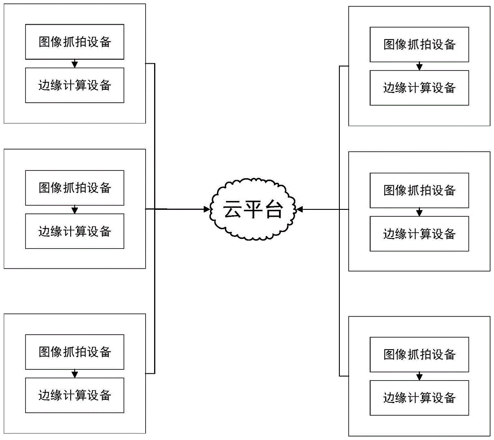
in a first aspect, the invention provides a traffic flow prediction system based on the internet of things and edge computing, which comprises a cloud platform, and image capturing equipment and edge computing equipment which are installed at different positions on a road;
the image capturing device is used for capturing images of passing traffic flows in real time, and the driving direction of the vehicles captured by the same image capturing device is fixed;
the edge computing equipment is matched with the image capturing equipment one by one and is used for acquiring the traffic flow images shot by the image capturing equipment at the same position, positioning each license plate area in the traffic flow images through a built-in license plate positioning model and identifying license plates in each license plate area through a license plate identification model;
the cloud platform is in communication connection with edge computing equipment at different positions through the Internet of things, and a data receiving module, a data fusion module and a traffic flow prediction module are arranged in the cloud platform;
the data receiving module is used for receiving license plate number identification results reported by edge computing equipment at different positions in real time, corresponding timestamps and vehicle running directions;
the data fusion module is used for performing correlation fusion on each license plate number reported by each edge computing device, the corresponding timestamp, the vehicle running direction and the coordinate where the edge computing device is located to form a track point, restoring the running track of the corresponding vehicle by calling a path planning algorithm through all continuous track points of each license plate number, and storing the running track of all vehicles as traffic flow data in a historical traffic flow database;
the traffic flow prediction module is used for reading the stored traffic flow data from a historical traffic flow database and predicting the traffic flow at the future moment based on a trained traffic flow prediction model.
Preferably, the image capture device and the edge calculation device are installed in pairs at the intersection position of the road.
Preferably, the license plate location model is a YOLO model.
Preferably, the license plate recognition model is a CNN convolutional neural network model.
Preferably, the traffic flow prediction module is provided with a designation module for inputting a prediction region and a prediction time.
Preferably, the traffic flow prediction model is a multi-direction traffic flow prediction model and comprises a first fully-connected neural network, a second fully-connected neural network, a three-dimensional residual convolution network and a recalibration layer, the input of the multi-direction traffic flow prediction model is a traffic flow three-dimensional matrix, a time signal vector and an interest point signal, the first fully-connected neural network outputs a time signal matrix according to the time signal vector, the second fully-connected neural network outputs an interest point signal matrix according to the interest point signal, the three-dimensional residual convolution network outputs a result matrix according to the fusion characteristics of the traffic flow three-dimensional matrix, the interest point signal matrix and the time signal matrix, and finally the result matrix is subjected to weighted compression operation in the recalibration layer to obtain a multi-direction traffic flow prediction result.
Preferably, the license plate positioning model and the license plate recognition model are downloaded in the edge computing device after being trained in advance.
Preferably, the traffic flow prediction model in the cloud platform is continuously trained by adopting an incremental learning method.
Preferably, the image capturing device is a camera arranged above the intersection, and each camera captures images only towards the traffic flow driving direction.
Preferably, the traffic flow three-dimensional matrix, the time signal vector and the interest point signal are generated by the following method:
s1, obtaining historical traffic flow data before a to-be-predicted time in an area to be predicted, wherein the historical traffic flow data comprises positions of different vehicles in the area to be predicted at different times and vehicle running directions; extracting a plurality of traffic data time slices from the historical traffic data according to a preset time slice interval;
s2, rasterizing an area to be predicted to be divided into a series of grids, mapping vehicles in each traffic flow data time slice to corresponding grids of the area to be predicted according to coordinates of the vehicles, and defining the driving direction of the vehicles as the moving state of the vehicles in the grids, wherein the moving state comprises four states of upward, downward, leftward and rightward; counting the total number of vehicles in each moving state contained in each grid in each time slice, taking the counted total number as a grid value, mapping the grid value into matrix elements, and accordingly respectively constructing traffic flow two-dimensional matrixes for different moving states in each time slice, and superposing the traffic flow two-dimensional matrixes in all the time slices in each moving state according to the time dimension to form a traffic flow three-dimensional matrix;
s3, extracting an hour field and a minute field from the moment to be predicted, and splicing to form a binary time signal vector;
s4, obtaining the spatial geographic positions of all interest Points (POIs), mapping the interest points of different functional categories into grids of the area to be predicted, counting the total number of the interest points of each group of functional categories in each grid, taking the counted number as a grid value, mapping the grid value into a matrix element, respectively constructing an interest point slice of each group of functional categories in a two-dimensional matrix form, and overlapping the interest point slices of all the functional categories to form an interest point signal of a three-dimensional tensor form.
In a second aspect, the invention provides a cloud platform for cooperating with image capture devices and edge computing devices installed at different positions on a road to realize traffic flow prediction;
the image capturing device is used for capturing images of passing traffic flows in real time, and the driving direction of the vehicles captured by the same image capturing device is fixed;
the edge computing equipment is matched with the image capturing equipment one by one and is used for acquiring the traffic flow images shot by the image capturing equipment at the same position, positioning each license plate area in the traffic flow images through a built-in license plate positioning model and identifying license plates in each license plate area through a license plate identification model;
the cloud platform is in communication connection with edge computing equipment at different positions through the Internet of things, and a data receiving module, a data fusion module and a traffic flow prediction module are arranged in the cloud platform;
the data receiving module is used for receiving license plate number identification results reported by edge computing equipment at different positions in real time, corresponding timestamps and vehicle running directions;
the data fusion module is used for performing correlation fusion on each license plate number reported by each edge computing device, the corresponding timestamp, the vehicle running direction and the coordinate where the edge computing device is located to form a track point, restoring the running track of the corresponding vehicle by calling a path planning algorithm through all continuous track points of each license plate number, and storing the running track of all vehicles as traffic flow data in a historical traffic flow database;
the traffic flow prediction module is used for reading the stored traffic flow data from a historical traffic flow database and predicting the traffic flow at the future moment based on a trained traffic flow prediction model.
Compared with the prior art, the invention has the following beneficial effects:
according to the invention, the traffic flow images are captured by the image capturing equipment on the road, and then license plate positioning and recognition are carried out on the traffic flow images through the edge computing equipment at the local end, so that traffic flow information passing through different positions is obtained, the data volume needing to be uploaded to a cloud platform is greatly reduced, the processing efficiency is improved, and the load of a cloud end is reduced. In addition, the vehicle information is only acquired at the local end, so that a higher response speed can be provided, and the time delay of the cloud platform for acquiring the real-time traffic flow information is reduced. The method can aggregate all traffic flow track information in the whole prediction area on the cloud platform, and predict the traffic flow at the future moment through the traffic flow prediction model carried on the cloud platform.
Detailed Description
In order to make the objects, technical solutions and advantages of the present invention more apparent, the present invention is further described in detail below with reference to the accompanying drawings and embodiments. It should be understood that the specific embodiments described herein are merely illustrative of the invention and do not limit the invention.
On the contrary, the invention is intended to cover alternatives, modifications, equivalents and alternatives which may be included within the spirit and scope of the invention as defined by the appended claims. Furthermore, in the following detailed description of the present invention, certain specific details are set forth in order to provide a better understanding of the present invention. It will be apparent to one skilled in the art that the present invention may be practiced without these specific details.
The invention provides a traffic flow prediction system based on the Internet of things and edge computing, which comprises a cloud platform, and image capturing equipment and edge computing equipment which are installed at different positions on a road.
The edge computing equipment and the image capturing equipment are paired one by one, and each pair of the image capturing equipment and the edge computing equipment are connected through a signal line and are installed at one position on a road. In order to facilitate image capturing, the edge computing device and the image capturing device are preferably installed on the road intersection.
The image capturing device is used for capturing passing vehicle flow images in real time, and the driving direction of a vehicle captured by the same image capturing device is fixed. In addition, the edge computing equipment is used for acquiring the traffic flow images shot by the image capturing equipment at the same position, positioning each license plate area in the traffic flow images through a built-in license plate positioning model, and identifying license plate numbers in each license plate area through a license plate identification model.
In practical application, the image capturing equipment can directly adopt the cameras arranged above the intersection, and each camera only shoots towards the traffic flow driving direction. Since the traveling direction of the vehicle captured by each image capturing apparatus is fixed, the traveling direction of the vehicle recognized from the image captured by the image capturing apparatus is also fixed. In the invention, the license plate positioning model and the license plate recognition model can be realized by adopting any network model capable of realizing license plate positioning and license plate recognition. For example, the license plate location model may adopt a YOLO model, preferably a YOLO V3 model, and the license plate recognition model may adopt a CNN convolutional neural network model. The license plate positioning model and the license plate recognition model are downloaded in the edge computing equipment after being trained in advance.
Because the edge computing device processes the image data at the local end, the edge computing device only needs to send the license plate number data to the cloud platform, so that the network uplink data volume is greatly reduced, and the real-time performance of the cloud platform on data acquisition can be improved.
In addition, the cloud platform is in communication connection with edge computing devices in different positions through the Internet of things, and a data receiving module, a data fusion module and a traffic flow prediction module are arranged in the cloud platform.
The data receiving module is used for receiving license plate number identification results reported by edge computing equipment at different positions in real time, corresponding timestamps and vehicle running directions.
In practical applications, the vehicle driving direction may be determined according to the interfaces or IDs of the image capturing device and the edge computing devices from which the vehicle driving direction originates, and each edge computing device may store the corresponding vehicle driving direction in the cloud platform in advance.
The data fusion module is used for performing correlation fusion on each license plate number reported by each edge computing device, the corresponding timestamp, the vehicle running direction and the coordinate where the edge computing device is located to form a track point, restoring the running track of the corresponding vehicle by calling a path planning algorithm through all continuous track points of each license plate number, and storing the running track of all vehicles as traffic flow data in a historical traffic flow database.
In the invention, the path planning algorithm can be any algorithm which can generate the path track according to all the continuous track points of a vehicle, preferably Dijkstra algorithm is adopted, and certainly, map APIs (application program interfaces) such as a Baidu map or a Gaode map can also be directly called, and each track point is taken as a passing point to generate the path track. In the process of producing the path track, the time information of the path track also needs to be carried, namely, the other track points between any two track points on one path can generate corresponding time information in an interpolation mode.
The traffic flow prediction module is used for reading the stored traffic flow data from the historical traffic flow database and predicting the traffic flow at the future moment based on the trained traffic flow prediction model.
The traffic flow prediction model in the cloud platform needs to be trained in advance before being used, and in order to ensure the accuracy of the model, data continuously stored in the cloud platform can be used as samples and continuously trained by adopting an incremental learning method.
In order to consider different traffic flow prediction demands, a designated module for inputting prediction areas and prediction times may be provided in the traffic flow prediction module so as to input different prediction areas and different prediction times as needed.
In the present invention, the traffic flow prediction model used may be any network model capable of realizing traffic flow prediction, such as a space-time diagram neural network.
As a preferred embodiment of the present invention, the traffic flow prediction model may adopt a multi-directional traffic flow prediction model, which can distinguish directions after the trajectory of the vehicle is rasterized, and distinguish a moving state based on the direction of the trajectory when passing through the grid, thereby realizing multi-directional traffic flow prediction. The multi-direction traffic flow prediction model comprises a first full-connection neural network, a second full-connection neural network, a three-dimensional residual convolution network and a re-correction layer, wherein the input of the multi-direction traffic flow prediction model is a traffic flow three-dimensional matrix, a time signal vector and an interest point signal, the first full-connection neural network outputs the time signal matrix according to the time signal vector, the second full-connection neural network outputs the interest point signal matrix according to the interest point signal, the three-dimensional residual convolution network outputs a result matrix according to the fusion characteristics of the traffic flow three-dimensional matrix, the interest point signal matrix and the time signal matrix, and finally the result matrix is subjected to weighted compression operation in the re-correction layer to obtain a multi-direction traffic flow prediction result.
In the cloud platform, the method for predicting the traffic flow by using the multidirectional traffic flow prediction model comprises the following steps:
s1, obtaining historical traffic flow data before a to-be-predicted time in an area to be predicted, wherein the historical traffic flow data comprises positions of different vehicles in the area to be predicted at different times and vehicle running directions; and extracting a plurality of traffic data time slices from the historical traffic data according to a preset time slice interval.
In this embodiment, the region to be predicted in S1 is a rectangular region, and the time span of the historical traffic data is [ t, t + (m-1) × τ ], and it extracts m traffic data time slices at intervals of τ minutes.
S2, rasterizing an area to be predicted to be divided into a series of grids, mapping vehicles in each traffic flow data time slice to corresponding grids of the area to be predicted according to coordinates of the vehicles, and defining the driving direction of the vehicles as the moving state of the vehicles in the grids, wherein the moving state comprises four states of upward, downward, leftward and rightward; and counting the total number of vehicles in each moving state contained in each grid in each time slice, taking the total number as a grid value, mapping the grid value into matrix elements, and accordingly respectively constructing traffic flow two-dimensional matrixes for different moving states in each time slice, wherein the traffic flow two-dimensional matrixes in all the time slices of each moving state are superposed according to time dimension to form a traffic flow three-dimensional matrix. The moving state of the vehicle in the grid can be determined according to the driving direction of the vehicle when the driving track of the vehicle passes through the grid.
In this embodiment, the specific implementation steps of S2 are as follows:
s21, rasterizing the area to be predicted, and dividing the area to be predicted into I × J grids, wherein the grid in the ith row and the jth column is P ij ;
And S22, mapping the vehicles in each traffic data time slice to a corresponding grid of the area to be predicted according to the coordinates of the vehicles, and defining the driving direction of the vehicles as the moving states of the vehicles in the grid, wherein the moving states comprise four states of upward, downward, leftward and rightward.
Since the traveling direction of the vehicle is actually a 360 ° directional space, the 360 ° directional space needs to be divided at intervals of 90 °. An XY coordinate system on a map plane is established by taking the position of a vehicle as an origin, the whole 360-degree direction space is divided into four subspaces with an upward opening, a downward opening, a leftward opening and a rightward opening by using two straight lines of y = x and y = -x, and the opening direction of the corresponding subspace is taken as the moving state of the vehicle in the grid when the driving direction of the vehicle with the position of the vehicle as the origin is positioned in the subspace.
S23, counting the total number of vehicles in each moving state contained in each grid in each time slice t, and counting the grids P in the time slice t
ij The traffic flow with the moving state d is recorded
All I X J grids are corresponded
The method is constructed into a traffic flow two-dimensional matrix with a moving state d in the whole area to be predicted in a time slice t
Traffic flow two-dimensional matrix
In the ith row and the jth column has element values of
S24, carrying out time slice traffic flow two-dimensional matrix on all m traffic flow data
Splicing according to time dimension to form traffic flow three-dimensional matrix
And S3, extracting an hour field and a minute field from the time to be predicted, and splicing to form a binary time signal vector.
In this embodiment, the specific implementation steps of S3 are as follows:
the time t to be predicted pred Is converted intoContaining an hour field t pred_hour And a minute field t pred_minute Two-element time signal vector h t =[t pred_hour ,t pred_minute ]。
S4, obtaining the spatial geographic positions of all interest points, mapping the interest points of different functional categories to grids of the area to be predicted, counting the total number of the interest points of each group of functional categories in each grid, taking the counted number as a grid value, mapping the grid value into a matrix element, and accordingly respectively constructing an interest point slice in a two-dimensional matrix form for the interest points of each group of functional categories, and overlapping the interest point slices of all functional categories to form an interest point signal in a three-dimensional tensor form.
The POI is a geographic entity for realizing the city function, and reflects the influence of different departure places and destinations on the change of traffic volume. For example, dining POIs affect traffic in surrounding areas at lunch and dinner times, while tourist attraction POIs primarily affect traffic on weekends and holidays. In this embodiment, the interest point groups may be classified according to 9 types, i.e., food and drink, shopping service, daily life service, medical service, accommodation service, tourist attraction, education service, transportation service, and others, and of course, other classification forms may be adopted.
In this embodiment, the specific implementation steps of S4 are as follows:
s41, acquiring the spatial geographic positions of all interest points, and mapping all interest points to P of the area to be predicted according to the positions of the interest points ij In the grid;
s42, dividing all the interest points into n groups according to different function categories, and counting the number of the interest point groups g in the grid P
ij The number of interest points in and as a grid P
ij Grid value of
Grouping the grid values of all grids corresponding to each interest point group g
Constructed as point of interest group g correspondencesIs sliced gamma to the point of interest
g ,γ
g Size I x J;
s43, all the interest point slices corresponding to the n groups of interest point groups are spliced to obtain an interest point signal psi = [ gamma ] ( i ,γ 2 ,…,γ n ]And the size is n I J.
And S5, taking the traffic flow three-dimensional matrix, the time signal vector and the interest point signal as the input of a trained multidirectional traffic flow prediction model, wherein the multidirectional traffic flow prediction model comprises a first fully-connected neural network, a second fully-connected neural network, a three-dimensional residual convolution network and a re-correction layer.
In this embodiment, the specific implementation steps of S5 are as follows:
s51: the traffic flow three-dimensional matrix
The time signal vector h
t Inputting the interest point signal psi into a trained multidirectional traffic flow prediction model, wherein the multidirectional traffic flow prediction model comprises a first fully-connected neural network, a second fully-connected neural network, a three-dimensional residual convolution network and a re-correction layer;
s52, the time signal h
t Is input to the input terminal including L
ts In the first fully-connected neural network of layer fully-connected layer cascade, the input of the 1 st fully-connected layer is a time signal h
t The input of the next full link layer is the output of the previous full link layer, and the output of the last full link layer is
Will be provided with
The vector is mapped element by element into a matrix with the size (I X J) to obtain a time signal matrix H with the size (I, J)
t ;
S53, the interest point signal psi = [ gamma ] 1 ,γ 2 ,…,γ n ]After input, each interest point is firstly checkedSlicing gamma g Obtain its average self-weight z g :
Obtaining an average self-weight matrix Z = { Z) of the interest point signal Ψ 1 ,z 2 ,…,z n H, wherein n represents the number of interest point groups;
then the average self-weight matrix Z input is included with L
ps Calculating layer by the second fully-connected neural network of the layer fully-connected layer cascade, wherein the input of the 1 st fully-connected layer is the average self-weight matrix Z, the input of the next fully-connected layer is the output of the previous fully-connected layer, and the output of the last fully-connected layer is
Then, the output is output by adopting a door mechanism
The mapping is a variable between 0 and 1, and the calculation process is as follows:
wherein f is si Activating a function for the ReLU;
finally, obtaining interest point signal matrix through calculation
Wherein, an indicates a matrix dot product;
s54, traffic flow three-dimensional matrix
Interest point signal matrix
Sum time signal matrix H
t The characteristic fusion is carried out, and the characteristic fusion is carried out,
the fusion characteristic of the kth traffic data time slice in (1)
The calculation formula is as follows:
wherein,
and
are trainable parameters, m is
The number of the middle traffic flow data time slices;
finally obtaining the fused traffic flow matrix
S55, merging the traffic flow matrix X Γ The input comprises L c Calculating layer by layer in a three-dimensional residual convolutional network formed by cascading layer three-dimensional residual convolutional layers, wherein an input traffic flow matrix X of the first layer of three-dimensional residual convolutional layer Γ The result obtained after the three-dimensional residual error convolution layer of each layer is used as the input of the next three-dimensional residual error convolution layer, and the outputs of all three-dimensional residual error convolution layers in the three-dimensional residual error convolution network are spliced to form a final result matrix X ST (ii) a Wherein for any l-th layer three-dimensional residual convolution layer, the three-dimensional residual convolution layer executed thereinThe difference convolution operation is as follows:
firstly, performing three-dimensional convolution operation on the input of a current three-dimensional residual convolution layer to obtain a convolution result:
wherein Cov3D represents a three-dimensional convolution operation,
represents the output of the l-1 layer three-dimensional residual convolution layer, wherein
And
for the trainable parameters of the l-th layer of three-dimensional convolution (i.e., the aforementioned three-dimensional convolution operation Cov 3D), f
c Activating a function for the ReLU;
then, the convolution result outputted to the three-dimensional convolution layer
Each element in the system is subjected to batch regularization operation to obtain a batch regularization result
The formula is as follows:
wherein E [ x ] represents the mean value of each dimensional matrix, var [ x ] is the variance of each dimensional matrix, epsilon is a constant set to prevent the variance from being 0, and gamma and beta are learnable parameters;
finally, the result is batched and normalized
And then with the output matrix of the previous layer
Adding to obtain the output matrix of the l-th layer three-dimensional residual convolution layer
The formula is as follows:
s56, in the re-correction layer, the final output result matrix X
ST All the dimensions are subjected to weighted compression operation to obtain a prediction result
The calculation formula is as follows:
wherein
Is a learnable parameter matrix.
It should be noted that, in S5, the multi-directional traffic flow prediction model is trained in advance through training data, and the prediction result is continuously iterated through the loss function during the training process
And outputting a multidirectional traffic flow prediction model for actual prediction when the loss value between the actual result phi and the real result phi reaches an iteration termination condition.
The Loss function Loss as a multidirectional traffic flow prediction model is realized by the following formula:
wherein
Is a matrix
The value of each of the elements in (a),
for each element value in the matrix Φ, M is the number of training samples.
The multi-direction traffic flow prediction model can effectively realize the prediction of traffic flows in different directions, and the prediction precision of the multi-direction traffic flow prediction model is obviously superior to that of the traditional mathematical method and the machine learning related method.
In another embodiment of the invention, a cloud platform is further provided, which is used for realizing traffic flow prediction in cooperation with image capturing equipment and edge computing equipment which are installed at different positions on a road;
the image capturing device is used for capturing passing vehicle flow images in real time, and the driving direction of a vehicle captured by the same image capturing device is fixed;
the edge computing equipment is matched with the image capturing equipment one by one and is used for acquiring the traffic flow images shot by the image capturing equipment at the same position, positioning each license plate area in the traffic flow images through a built-in license plate positioning model and identifying license plates in each license plate area through a license plate identification model;
the cloud platform is in communication connection with edge computing equipment at different positions through the Internet of things, and a data receiving module, a data fusion module and a traffic flow prediction module are arranged in the cloud platform;
the data receiving module is used for receiving license plate number recognition results reported by edge computing equipment at different positions in real time, corresponding timestamps and vehicle running directions;
the data fusion module is used for performing correlation fusion on each license plate number reported by each edge computing device, the corresponding timestamp, the vehicle running direction and the coordinate where the edge computing device is located to form a track point, restoring the running track of the corresponding vehicle by calling a path planning algorithm through all continuous track points of each license plate number, and storing the running track of all vehicles as traffic flow data in a historical traffic flow database;
the traffic flow prediction module is used for reading the stored traffic flow data from a historical traffic flow database and predicting the traffic flow at the future moment based on a trained traffic flow prediction model.
It should be noted that, in the cloud platform, the specific implementation manner in each module may also be the method in the traffic flow prediction system based on the internet of things and edge computing, and details are not repeated here.
The above-described embodiments are merely preferred embodiments of the present invention, and are not intended to limit the present invention. Various changes and modifications may be made by one of ordinary skill in the pertinent art without departing from the spirit and scope of the present invention. Therefore, the technical solutions obtained by means of equivalent substitution or equivalent transformation all fall within the protection scope of the present invention.