Disclosure of Invention
The invention aims to provide a novel technical scheme of a laser cutting dust collecting device and a method.
According to a first aspect of the present invention, there is provided a laser cutting dust collecting apparatus, comprising:
a vacuum chamber having an air inlet;
and the flow direction control device is arranged in the vacuum cavity and can control the air inlet direction of the air inlet.
Optionally, the flow direction control device includes a movable plate and a control device, the movable plate is movably disposed in the vacuum chamber, and the control device can control the movable plate to move;
the movable plate blocks the vacuum cavity under the condition that the control device controls the movable plate to be located at the first position;
under the condition that the control device controls the movable plate to be located at the second position, the vacuum cavity has the maximum flow rate at the position of the movable plate;
the movable plate is movable between the first position and the second position, and the intake ports have different intake directions in a case where the movable plate is located at different positions between the first position and the second position.
Optionally, the flow direction control device includes a plurality of the movable plates, the movable plates are sequentially distributed along the flow direction of the vacuum chamber, and the control device can control the movable plates to move independently.
Optionally, the vacuum chamber is provided with a multi-degree-of-freedom transmission shaft, the movable plate is connected with the multi-degree-of-freedom transmission shaft, and the movable plate can rotate around the multi-degree-of-freedom transmission shaft so as to be movable between the first position and the second position.
Optionally, the movable plate is hinged to the vacuum chamber, the movable plate being swingable about a hinged axis to move between the first position and the second position.
Optionally, the vacuum chamber has a plurality of said gas inlets.
Optionally, the vacuum cavity is an annular cavity having a first end surface, and the plurality of air inlets are uniformly distributed along the first end surface.
Optionally, the vacuum chamber is provided with a plurality of vacuum pipes, and the plurality of vacuum pipes correspond to the plurality of air inlets one to one.
According to a second aspect of the present invention, there is provided a laser cutting dust collecting method applied to the laser cutting dust collecting apparatus according to the first aspect, wherein the method comprises:
starting the laser cutting dust collecting device;
the air inlet direction of the air inlet of the vacuum cavity is controlled by the flow direction control device.
Alternatively, the controlling of the air intake direction of the air intake port of the vacuum chamber by the flow direction control means includes:
the movable plate is controlled to move between the first position and the second position through the control device, so that the air inlet direction of the air inlet is controlled.
According to one embodiment of the disclosure, the laser cutting dust can be sucked into the laser cutting dust collecting device along with the air flow, and in the sucking process, the air inlet direction of the air inlet is controlled through the flow direction control device, so that the moving direction of the dust can be adjusted, and the scattering position of the scattered dust can be controlled.
Other features of the present invention and advantages thereof will become apparent from the following detailed description of exemplary embodiments thereof, which proceeds with reference to the accompanying drawings.
Detailed Description
Various exemplary embodiments of the present invention will now be described in detail with reference to the accompanying drawings. It should be noted that: the relative arrangement of the components and steps, the numerical expressions and numerical values set forth in these embodiments do not limit the scope of the present invention unless specifically stated otherwise.
The following description of at least one exemplary embodiment is merely illustrative in nature and is in no way intended to limit the invention, its application, or uses.
Techniques, methods, and apparatus known to those of ordinary skill in the relevant art may not be discussed in detail but are intended to be part of the specification where appropriate.
In all examples shown and discussed herein, any particular value should be construed as exemplary only and not as limiting. Thus, other examples of the exemplary embodiments may have different values.
It should be noted that: like reference numbers and letters refer to like items in the following figures, and thus, once an item is defined in one figure, further discussion thereof is not required in subsequent figures.
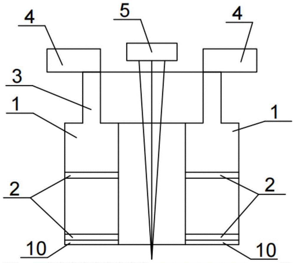
In one embodiment of the present disclosure, there is provided a laser cutting dust collecting apparatus, as shown in fig. 1 to 3, including:
a vacuum chamber 1, the vacuum chamber 1 having an inlet port 10.
And a flow direction control device which is provided in the vacuum chamber 1 and is capable of controlling the air intake direction of the air intake port 10.
In this embodiment, the laser cutting dust is sucked into the laser cutting dust collecting device along with the air flow, and during the suction process, the air inlet direction of the air inlet 10 is controlled by the flow direction control device, so that the moving direction of the dust can be adjusted, and the scattering position of the scattered dust can be controlled.
In the laser cutting process, the laser cutting device 5 emits laser to cut the workpiece. The vacuum chamber 1 is connected to a vacuum system 4, and a vacuum negative pressure is applied to the vacuum chamber 1 by the vacuum system 4, so that the gas outside the gas inlet 10 flows in the vacuum chamber. External gas enters the vacuum chamber 1 through the gas inlet 10, and flows from the vacuum chamber 1 to the vacuum system 4 to be disposed at an outlet.
In the process of cutting a workpiece by the laser cutting device 5 in the laser cutting process, dust generated by cutting can enter the vacuum cavity 1 along with the airflow flowing to the air inlet 10 and finally enter the device for collecting dust along with the airflow. In the process of collecting dust, part of the dust cannot enter the air inlet 10 and is scattered towards the workpiece. The flow direction control device in the present disclosure can control the air intake direction of the air intake port 10, and by controlling the air intake direction of the air intake port 10, the scattering direction of the dust that moves and scatters with the air flow can be controlled. By controlling the scattering direction of the dust, the scattered dust can be more intensively scattered in one area, so that the dust can be further cleaned. For example, during the laser cutting process, the laser cutting device 5 moves according to the processing rule, and the flow direction control device is correspondingly adjusted according to the cutting track of the laser cutting device 5, so that the dust during the cutting process always falls towards one area.
For example, the air inlet direction of the air inlet 10 controlled by the flow direction control device is preset according to the cutting track, and the air inlet direction is correspondingly changed along with the change of the cutting track, so that the scattered dust falls to the concentrated area.
Alternatively, on the basis of changing the air inlet direction of the air inlet 10, the falling position of the dust during the dust collection can be influenced by matching the air inlet speed. For example, increasing the negative pressure in the vacuum chamber 1 increases the flow velocity of the air flow, and the increased flow velocity can cause dust to have a greater velocity after leaving the air intake direction than when the flow velocity is small, thereby affecting the position where the dust falls. The flow rate of the air stream is set as required for the particular location where the dust falls.
In one embodiment, as shown in fig. 1 to 3, the flow direction control device includes a movable plate 2 and a control device, the movable plate 2 is movably disposed in the vacuum chamber 1, and the control device can control the movable plate 2 to move.
In case the control means controls the movable plate 2 to be in the first position, the movable plate 2 blocks the vacuum chamber 1. For example, as shown in fig. 1, the movable plate 2 is located at a first position covering the air inlet 10 so that the vacuum chamber 1 is blocked, and the air inlet 10 has an intake air amount of 0.
In case the control means controls the movable plate 2 to be located at the second position, the vacuum chamber 1 has the maximum flow rate at the position where the movable plate 2 is located. For example, as shown in fig. 2, the movable plate 2 is located at the second position, and the movable plate 2 is arranged in parallel with the airflow direction in the vacuum chamber 1, so that the movable plate 2 forms the minimum resistance to the airflow, and the airflow with the maximum flow rate can pass through the vacuum chamber 1.
The flap 2 is movable between the first position and the second position, the intake port 10 having different intake directions in the case where the flap 2 is located at different positions between the first position and the second position. When the movable plate 2 is located at different positions between the first position and the second position, the movable plate 2 is located at different positions having different spaces through which the airflow can pass, so that the movable plate 2 can influence the air intake direction of the air intake 10 by controlling the movable plate 2 to move between the first position and the second position.
Optionally, the control device includes a control chip and a control structure, and the control structure is a structure capable of driving the movable plate 2 to move. The control chip is used for enabling the control structure to move. For example, the control chip is located in the main control device of the laser cutting dust collecting device, and the main control device can be a PC terminal. The control structure is arranged in the vacuum cavity 1, the program of the movable plate 2 is arranged through the main control equipment, and the movable plate 2 is controlled to move through the control structure.
In one embodiment, the flow direction control means comprises a steering means arranged at the air inlet 10 and a movable flexible tube structure controlled by the steering means. For example, the steering device drives the flexible tube structure to rotate, so that the position of the nozzle of the flexible tube structure faces different directions. The flexible tube structure is in communication with the air inlet 10 and the orientation of the mouth of the flexible tube structure determines the direction of air inlet to control the direction of the dust collecting air flow.
The flexible pipe structure may be a pipe structure formed by a material with elasticity, for example, a hose, and the position of the nozzle is changed by bending the end of the hose, so as to change the air inlet direction. The flexible pipe structure can also be formed by assembling a plurality of special pipes, and the orientation of the tail end special pipe is changed by matching the plurality of special pipes, so that the air inlet direction is changed.
In one embodiment, as shown in fig. 1-2, the flow direction control device includes a plurality of the movable plates 2, the plurality of the movable plates 2 are sequentially distributed along the flow direction of the vacuum chamber, and the control device can control the plurality of the movable plates 2 to independently move.
In this embodiment, the plurality of movable plates 2 can affect the airflow in the flow direction of the airflow, and the intake direction of the air intake port 10 can be adjusted more precisely by cooperation between the plurality of movable plates 2, thereby more precisely controlling the area where the dust is scattered.
In one embodiment, the movable plate 2 is hinged with the vacuum chamber 1, and the movable plate 2 is swingable about a hinged axis to move between the first position and the second position.
In this embodiment, the movable plate 2 is hinged in the vacuum chamber 1, and the movable plate 2 is driven to rotate around the axis of the hinge position by the control device. When the movable plate 2 rotates to different positions, the movable plate 2 exerts different influences on the air flow in the vacuum chamber 1. For example, the movable plate 2 is moved to a position in an area between the first position and the second position to change the flow rate at the position.
In one embodiment, the vacuum chamber 1 is provided with a multi-degree-of-freedom transmission shaft, the movable plate 2 is connected with the multi-degree-of-freedom transmission shaft, and the movable plate 2 can rotate around the multi-degree-of-freedom transmission shaft to be movable between the first position and the second position.
In this embodiment, the multi-degree-of-freedom transmission shaft forms a support for the movable plate 2, and the control device controls the movable plate 2 to rotate, so that the movable plate 2 has a corresponding influence on the airflow of the vacuum chamber 1. For example, the output end of the multi-degree-of-freedom transmission shaft is fitted to the central region of the movable plate 2. The multi-degree-of-freedom transmission shaft can rotate in multiple directions, so that the movable plate 2 can be adjusted to change the airflow flowing in multiple directions, and the air inlet direction of the air inlet 10 is affected.
For example, the influence of the plurality of moving plates 2 on the air flow is controlled, so that the intake direction of the intake port 10 can be adjusted more accurately.
In one embodiment, as shown in fig. 1 to 3, the vacuum chamber 1 has a plurality of said gas inlets 10. As shown in fig. 3, the structure of the side where the air intake 10 is located is shown.
The plurality of air inlets 10 can increase the amount of air taken for dust collection and the dust collection coverage area to improve the dust collection effect, so that more dust can be sucked by the laser cutting dust collection device.
For example, the flow direction control means can control the intake direction of each intake port 10.
Optionally, a movable plate 2 is disposed inside each air inlet 10, and each air inlet 10 can be influenced by the corresponding movable plate 2 in the air inlet direction.
In one embodiment, as shown in fig. 1 to 3, the vacuum chamber 1 is an annular chamber having a first end surface, and the plurality of gas inlets 10 are uniformly distributed along the first end surface.
The inner side of the ring-shaped structure is provided with a hollow area, and laser emitted by the laser cutting device 5 reaches a workpiece through the hollow area. The plurality of air inlets 10 are uniformly distributed on the first end surface facing the side of the workpiece to be processed, so that the air flow in the dust collecting process can effectively collect dust on the peripheral side area of the processing position.
In one embodiment, as shown in fig. 1 to 3, the vacuum chamber 1 is provided with a plurality of vacuum ducts 3, and the plurality of vacuum ducts 3 correspond to the plurality of gas inlets 10 one to one.
In the modified embodiment, the vacuum chamber 1 is connected to the vacuum system 4 through a plurality of vacuum pipes 3, and vacuum negative pressure is formed in the vacuum pipes 3 and the vacuum chamber 1, so that air flows in through a plurality of air inlets 10. Each vacuum line 3 corresponds to the position of one air inlet 10, for example, the end of the vacuum line 3 is directed to one air inlet 10, so that the air flow of the air inlet 10 is influenced more directly by the vacuum line 3.
According to an embodiment of the present disclosure, there is provided a laser cutting dust collecting method applied to a laser cutting dust collecting apparatus in an embodiment of the present disclosure, wherein the method includes:
and starting the laser cutting dust collecting device.
The air intake direction of the air intake 10 of the vacuum chamber 1 is controlled by the flow direction control means.
During the processing, the laser cutting dust collecting device is started to generate negative pressure in the vacuum cavity 1, and the air inlet 10 is used for air inlet. The air inlet direction of the air inlet 10 is controlled to collect dust, so that scattered dust is concentrated and falls to one area. The concentration effect of scattered dust is improved.
In one embodiment, the controlling of the air intake direction of the air intake port 10 of the vacuum chamber 1 by the flow direction control means includes:
the movable plate 2 is controlled by a control device to move between a first position and a second position so as to control the air intake direction of the air intake 10.
The movable plate 2 is controlled to move, so that the movable plate 2 changes the structure inside the vacuum chamber 1, thereby changing the flowing mode of the air flow and further changing the air inlet direction of the air inlet 10.
In one embodiment, the air intake direction of the air intake 10 is set according to the cutting route by controlling the PC terminal of the production. For example, the specific position where the movable plate 2 moves is set according to the cutting route. A reference system is provided, coordinates of the movable plate 2 on the axis X, Y, Z are preset, and functions of the movement of the movable plate 2 are set according to the direction of dust collection required. The movable plate 2 is controlled to move according to the set function, so that the air inlet direction is influenced, and scattered dust can fall to a preset dust collection area. The direction of the air intake changes with the change of the cutting position during dust collection.
In the above embodiments, the differences between the embodiments are described in emphasis, and different optimization features between the embodiments can be combined to form a better embodiment as long as the differences are not contradictory, and further description is omitted here in consideration of brevity of the text.
Although some specific embodiments of the present invention have been described in detail by way of examples, it should be understood by those skilled in the art that the above examples are for illustrative purposes only and are not intended to limit the scope of the present invention. It will be appreciated by those skilled in the art that modifications may be made to the above embodiments without departing from the scope and spirit of the invention. The scope of the invention is defined by the appended claims.