CN114472425B - Cleaning equipment - Google Patents
Cleaning equipment Download PDFInfo
- Publication number
- CN114472425B CN114472425B CN202210074410.5A CN202210074410A CN114472425B CN 114472425 B CN114472425 B CN 114472425B CN 202210074410 A CN202210074410 A CN 202210074410A CN 114472425 B CN114472425 B CN 114472425B
- Authority
- CN
- China
- Prior art keywords
- lifting
- hanging
- arm
- hanger
- station
- Prior art date
- Legal status (The legal status is an assumption and is not a legal conclusion. Google has not performed a legal analysis and makes no representation as to the accuracy of the status listed.)
- Active
Links
- 238000004140 cleaning Methods 0.000 title claims abstract description 68
- 230000007246 mechanism Effects 0.000 claims abstract description 126
- 239000000725 suspension Substances 0.000 claims abstract description 92
- 238000001035 drying Methods 0.000 claims description 22
- 238000012546 transfer Methods 0.000 claims description 16
- 210000001503 joint Anatomy 0.000 claims description 12
- 238000011084 recovery Methods 0.000 claims description 2
- 230000003028 elevating effect Effects 0.000 abstract description 4
- 230000007306 turnover Effects 0.000 abstract description 2
- 238000000034 method Methods 0.000 description 10
- 230000008569 process Effects 0.000 description 10
- 238000010586 diagram Methods 0.000 description 5
- 238000007599 discharging Methods 0.000 description 4
- 230000006698 induction Effects 0.000 description 4
- 230000009286 beneficial effect Effects 0.000 description 2
- 238000010981 drying operation Methods 0.000 description 2
- 239000000463 material Substances 0.000 description 2
- 238000003825 pressing Methods 0.000 description 2
- 241000251468 Actinopterygii Species 0.000 description 1
- 241001391944 Commicarpus scandens Species 0.000 description 1
- 230000003749 cleanliness Effects 0.000 description 1
- 238000012423 maintenance Methods 0.000 description 1
- 238000004519 manufacturing process Methods 0.000 description 1
- 238000012986 modification Methods 0.000 description 1
- 230000004048 modification Effects 0.000 description 1
- 238000012545 processing Methods 0.000 description 1
- 230000008439 repair process Effects 0.000 description 1
- 239000011435 rock Substances 0.000 description 1
- 230000000087 stabilizing effect Effects 0.000 description 1
- 238000005406 washing Methods 0.000 description 1
Images



Classifications
-
- B—PERFORMING OPERATIONS; TRANSPORTING
- B08—CLEANING
- B08B—CLEANING IN GENERAL; PREVENTION OF FOULING IN GENERAL
- B08B13/00—Accessories or details of general applicability for machines or apparatus for cleaning
-
- B—PERFORMING OPERATIONS; TRANSPORTING
- B65—CONVEYING; PACKING; STORING; HANDLING THIN OR FILAMENTARY MATERIAL
- B65G—TRANSPORT OR STORAGE DEVICES, e.g. CONVEYORS FOR LOADING OR TIPPING, SHOP CONVEYOR SYSTEMS OR PNEUMATIC TUBE CONVEYORS
- B65G29/00—Rotary conveyors, e.g. rotating discs, arms, star-wheels or cones
-
- B—PERFORMING OPERATIONS; TRANSPORTING
- B65—CONVEYING; PACKING; STORING; HANDLING THIN OR FILAMENTARY MATERIAL
- B65G—TRANSPORT OR STORAGE DEVICES, e.g. CONVEYORS FOR LOADING OR TIPPING, SHOP CONVEYOR SYSTEMS OR PNEUMATIC TUBE CONVEYORS
- B65G47/00—Article or material-handling devices associated with conveyors; Methods employing such devices
- B65G47/74—Feeding, transfer, or discharging devices of particular kinds or types
- B65G47/90—Devices for picking-up and depositing articles or materials
Landscapes
- Engineering & Computer Science (AREA)
- Mechanical Engineering (AREA)
- Cleaning By Liquid Or Steam (AREA)
Abstract
The application relates to the technical field of automatic equipment and provides cleaning equipment, which comprises a rotating mechanism, a hanging frame and a lifting mechanism; the hanger is used for fixing the tray, the operation station includes at least one cleaning station and at least one stoving station, but a plurality of hangers are hung simultaneously through rotary mechanism's a plurality of suspension arms, rotary mechanism is used for driving the hanger and removes to corresponding operation station department, the rethread sets up in the elevating system who corresponds operation station department drives the work area of hanger business turn over operation station, rotary mechanism cooperates with elevating system, can realize rinsing simultaneously or stoving a plurality of trays, the hanger is circulated with the mode of circular motion between different operation stations, and the hanger of different operation station departments is with advancing simultaneously, all operation stations simultaneous working, whole cleaning equipment simple structure, compactness, area reduces greatly.
Description
Technical Field
The application belongs to the technical field of automation equipment, and more specifically relates to cleaning equipment.
Background
In the production and processing process of the PCB, the PCB is stored by adopting a tray generally, and the tray is inevitably stained with various stains in the repeated use process because the PCB generally has higher cleanliness requirement, so that the tray needs to be cleaned regularly to remove various stains on the tray. The existing automatic cleaning equipment for the PCB tray is generally provided with a plurality of stations for feeding, cleaning, drying, discharging and the like, materials are circulated among the stations in a linear motion mode, and the linear motion circulation mode leads to various parts of the cleaning equipment which are integrally moved, so that the automatic cleaning equipment is large in size, large in occupied area and easy to break down.
Disclosure of Invention
An aim of the embodiment of the application is to provide a cleaning equipment to solve the cleaning equipment that exists among the prior art and carry the material with linear motion mode and lead to the whole huge, the big technical problem of area of equipment.
In order to achieve the above purpose, the technical scheme adopted in the application is as follows: provided is a cleaning device, comprising a rotating mechanism, a hanging rack and a lifting mechanism;
the rotary mechanism comprises a rotary driving piece and a rotary frame connected with the rotary driving piece, a rotating shaft of the rotary driving piece drives the rotary frame to rotate, and an operation station is arranged below the periphery of the rotary frame and comprises at least one cleaning station and at least one drying station; the rotating frame comprises a rotating disc and a plurality of hanging arms uniformly arranged on the periphery of the rotating disc, and the free ends of the hanging arms extend to the operation station along a plane perpendicular to the rotating shaft; the hanging frame is used for fixing a tray, the hanging frame can be hung at the free end of the hanging arm, and the rotating mechanism is used for driving the hanging frame to move to the operation station;
the lifting mechanism comprises a lifting driving piece and a lifting arm, the lifting mechanism is arranged at the position corresponding to the cleaning station and the drying station respectively, the lifting arm is in butt joint with the hanging arm at the position of the operation station, the hanging frame can be transferred from the hanging arm to the lifting arm or from the lifting arm to the hanging arm, and the lifting mechanism is used for driving the hanging frame to enter and exit a working area of the operation station.
Optionally, the operation station further comprises a feeding station and a discharging station, wherein a hanging frame opening and clamping mechanism is respectively arranged at the feeding station and the discharging station; the hanging rack clamping opening mechanism comprises a lifting hook, the hanging rack can be hung on the lifting hook, and the lifting hook is in butt joint fit with the hanging arm so as to transfer the hanging rack.
Optionally, the stores pylon include hang structure and with hang structure connect be used for fixing a plurality of elasticity presss from both sides of tray, elasticity presss from both sides rectangular form, a plurality of elasticity presss from both sides parallel and the interval sets up, every elasticity presss from both sides is used for fixing one the tray, hang structure including lifting hook portion and parallel arrangement's first hanging beam and second hanging beam, a plurality of elasticity press from both sides connect in first hanging beam with between the second hanging beam, first hanging beam with the second hanging beam all is equipped with lifting hook portion.
Optionally, the elastic clip comprises a clamping part and an elastic push rod elastically connected with the clamping part, wherein the clamping part is opened along with the pushing of the pressed elastic push rod and is closed along with the recovery of the elastic push rod.
Optionally, the hanger opening and clamping mechanism further comprises a plurality of opening and clamping cylinders and a hook cylinder for driving the lifting hook to lift, wherein the hook cylinder is fixed on the first top plate, the plurality of opening and clamping cylinders are fixed on the second top plate, and the opening and clamping cylinders are correspondingly arranged with the elastic push rod to be abutted to and press down the elastic push rod.
Optionally, the hanger opening and clamping mechanism further comprises at least one positioning piece fixedly connected to the second top plate, and an opening and clamping lifting cylinder for driving the second top plate to lift, when the opening and clamping lifting cylinder drives the opening and clamping cylinder to butt against the elastic push rod, one end of the positioning piece is clamped with the first suspension beam, the other end of the positioning piece is clamped with the second suspension beam, and the positioning piece is perpendicular to the first suspension beam and the second suspension beam.
Optionally, the hook portion includes a first hook portion and a second hook portion, an open end of the first hook portion faces the suspension arm to interface with the suspension arm, and an open end of the second hook portion faces the lifting arm or the lifting hook to interface with the lifting arm or the lifting hook.
Optionally, the free end of the suspension arm, the lifting arm and the lifting hook are all provided with limiting blocks, the first hook part and the second hook part are all provided with limiting grooves, and the limiting blocks are clamped into the limiting grooves to limit the movement of the hanging frame along the X axis, the Y axis and the Z axis.
Optionally, the rotary mechanism further comprises a mounting plate, the rotary mechanism is fixed on the frame through the mounting plate, an induction block is arranged on the rotary disk corresponding to each position of the suspension arm, an angle sensor is arranged on the mounting plate, and the induction block can record the rotation angle of the rotary frame along with the rotation of the rotary disk and pass through an induction area of the angle sensor.
Optionally, the lifting arm is provided with an in-place sensor, and the in-place sensor is used for sensing that the suspension arm rotates to a position where the suspension arm is in butt joint with the lifting arm and giving in-place information.
The cleaning equipment who this application provided's beneficial effect lies in: compared with the prior art, the cleaning equipment comprises a rotating mechanism, a hanging frame and a lifting mechanism; the hanger is used for fixing the tray, the operation station includes at least one cleaning station and at least one stoving station, but a plurality of hangers are hung simultaneously through rotary mechanism's a plurality of suspension arms, rotary mechanism is used for driving the hanger and removes to corresponding operation station department, the rethread sets up in the elevating system who corresponds operation station department drives the work area of hanger business turn over operation station, rotary mechanism cooperates with elevating system, can realize rinsing simultaneously or stoving a plurality of trays, the hanger is circulated with the mode of circular motion between different operation stations, and the hanger of different operation station departments is with advancing simultaneously, all operation stations simultaneous working, whole cleaning equipment simple structure, compactness, area reduces greatly.
Drawings
In order to more clearly illustrate the technical solutions of the embodiments of the present application, the drawings that are required for the embodiments or the description of the prior art will be briefly described below, it being obvious that the drawings in the following description are only some embodiments of the present application, and that other drawings may be obtained according to these drawings without inventive effort for a person skilled in the art.
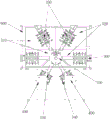
Fig. 1 is a schematic diagram of an overall structure of a cleaning apparatus according to an embodiment of the present application;
FIG. 2 is a top view of FIG. 1;
fig. 3 is a schematic structural diagram of a rotating mechanism according to an embodiment of the present disclosure;
FIG. 4 is a top view of FIG. 3;
fig. 5 is a schematic structural view of a hanger clamping tray according to an embodiment of the present disclosure;
FIG. 6 is a front view of a rotary mechanism and a hanger according to an embodiment of the present disclosure;
fig. 7 is a schematic structural diagram of a rotation mechanism driving a hanger to be abutted with a lifting mechanism according to an embodiment of the present application;
FIG. 8 is a schematic view of the lifting arm of FIG. 7 lifting and hanging rack off of the hanging arm;
fig. 9 is a schematic diagram of a rotating frame for rotating forward or backward at a certain angle to avoid a lifting arm according to an embodiment of the present application;
FIG. 10 is a schematic view of a lifting mechanism provided in an embodiment of the present application driving a hanger into a working area of an operating station;
FIG. 11 is a schematic structural view of a hanger opening mechanism and a hanger according to an embodiment of the present disclosure;
fig. 12 is a schematic structural view of an opening clip of a hanging frame opening clip mechanism according to an embodiment of the present application;
FIG. 13 is a schematic view of a rack opening mechanism and a rotating mechanism for transferring racks in cooperation with each other according to an embodiment of the present application;
fig. 14 is a schematic structural diagram of matching between a limiting block and a limiting groove according to an embodiment of the present application.
Wherein, each reference sign in the figure:
100. a rotation mechanism; 110. a rotary driving member; 120. a rotating frame; 121. a rotating disc; 1211. an induction block; 122. a suspension arm; 1221. a limiting block; 1222. a support fork structure; 130. a mounting plate; 131. an angle sensor; 200. a hanging rack; 210. a tray; 220. a suspension structure; 221. a hook portion; 2211. a first hook portion; 2212. a second hook portion; 2213. a limit groove; 222. a first cantilever beam; 223. a second cantilever beam; 230. an elastic clamp; 231. a clamping part; 2311. a first chuck; 2312. a second chuck; 232. an elastic push rod; 233. a rod body; 234. a fixed rod; 235. an elastic bolt; 300. a lifting mechanism; 310. a lifting arm; 311. an in-place sensor; 400. a hanging frame opening mechanism; 410. lifting the hook; 420. opening a clamping cylinder; 430. a hook cylinder; 440. opening a clamp lifting cylinder; 450. a first top plate; 460. a second top plate; 470. a positioning piece; 500. operating a station; 510. a cleaning station; 520. a drying station; 530. a feeding station; 540. a blanking station; 600. a frame.
Detailed Description
In order to make the technical problems, technical schemes and beneficial effects to be solved by the present application more clear, the present application is further described in detail below with reference to the accompanying drawings and embodiments. It should be understood that the specific embodiments described herein are for purposes of illustration only and are not intended to limit the present application.
It will be understood that when an element is referred to as being "mounted" or "disposed" on another element, it can be directly on the other element or be indirectly on the other element. When an element is referred to as being "connected to" another element, it can be directly connected to the other element or be indirectly connected to the other element.
It is to be understood that the terms "length," "width," "upper," "lower," "front," "rear," "left," "right," "vertical," "horizontal," "top," "bottom," "inner," "outer," and the like indicate or are based on the orientation or positional relationship shown in the drawings, merely to facilitate description of the present application and simplify description, and do not indicate or imply that the devices or elements referred to must have a particular orientation, be configured and operated in a particular orientation, and therefore should not be construed as limiting the present application.
Furthermore, the terms "first," "second," and the like, are used for descriptive purposes only and are not to be construed as indicating or implying a relative importance or implicitly indicating the number of technical features indicated. Thus, a feature defining "a first" or "a second" may explicitly or implicitly include one or more such feature. In the description of the present application, the meaning of "a plurality" is two or more, unless explicitly defined otherwise.
The cleaning device provided by the embodiment of the application is mainly applied to cleaning a PCB tray loaded with a PCB, and can be applied to cleaning workpieces similar to the PCB tray.
Referring to fig. 1 and 2, the cleaning apparatus of the present embodiment includes a rotating mechanism 100, a hanger 200 and a lifting mechanism 300.
Referring to fig. 2 and 3, the rotating mechanism 100 of the present embodiment includes a rotating driving member 110 and a rotating frame 120 connected to the rotating driving member 110, wherein a rotating shaft of the rotating driving member 110 drives the rotating frame 120 to rotate, an operation station 500 is disposed below the periphery of the rotating frame 120, and the operation station 500 includes at least one cleaning station 510 and at least one drying station 520; the rotating frame 120 comprises a rotating disc 121 and a plurality of hanging arms 122 uniformly arranged on the periphery of the rotating disc 121, and free ends of the hanging arms 122 extend to the operation station 500 along a plane perpendicular to the rotating shaft; referring to fig. 5 and 6, the hanger 200 is used for fixing the tray 210, the hanger 200 can be suspended at the free end of the suspension arm 122, and the rotating mechanism 100 is used for driving the hanger 200 to move to the operation station 500.
Specifically, the rotary driving member 110 in the rotary mechanism 100 may be a motor, and a servo motor, a stepping motor, or the like may be selected according to practical needs, and the rotary frame 120 is connected to a rotating shaft of the motor, that is, an output shaft, and the rotary frame 120 is connected to the rotating shaft and can rotate along with the rotating shaft. The rotating frame 120 comprises a rotating disc 121 and a plurality of hanging arms 122 uniformly arranged on the periphery of the rotating disc 121, the rotating frame 120 is connected with a rotating shaft through the rotating disc 121, the rotating disc 121 is sleeved on a bearing of the rotating shaft in a ring shape, the hanging arms 122 are fixed on the outer circumference of the rotating disc 121, and the hanging arms 122 can be fixedly connected to the rotating disc 121 through screws.
An operation station 500 is disposed below the periphery of the rotating frame 120 in this embodiment, the operation station 500 is used for cleaning, drying and other operations, the operation station 500 includes at least one cleaning station 510 and at least one drying station 520, for example, in one embodiment, an integral operation tank may be disposed directly below the periphery of the rotating frame 120, two interconnected cleaning tanks are separated inside the operation tank as cleaning stations 510, two interconnected drying tanks are separated as drying stations 520, the cleaning tanks are connected with the drying tanks, the operation station 500 is disposed below the rotating frame 120 in a circumferential manner, and correspondingly, the tray 210 is subjected to primary drying and secondary drying after primary cleaning and secondary cleaning in a circumferential movement manner along with the rotation of the rotating mechanism 100. Of course, separate and independent slots may be provided as distinct stations 500. Depending on the actual needs, a different number of the operation stations 500 may be provided, and operation stations 500 having functions other than cleaning and drying may be provided, which are not particularly limited herein.
Specifically, the fixed ends of the plurality of suspension arms 122 are fixed on the rotating disc 121, the free ends of the plurality of suspension arms 122 extend to the operation station 500 along a plane perpendicular to the rotating shaft, that is, the plurality of suspension arms 122 are equally distributed within 360 degrees of the plane of the rotating disc 121 with the rotating disc 121 as a center, and the suspension arms 122 can be disposed one-to-one with the operation station 500. For example, 6 suspension arms 122 may be provided, such that an included angle of 60 degrees is formed between every two suspension arms 122 in the 6 suspension arms 122, each suspension arm 122 may suspend one hanger 200, and the entire rotation mechanism 100 may simultaneously suspend 6 hangers 200 when operated, which may be understood that, in other embodiments, other numbers of suspension arms 122 may be provided, such as 8 suspension arms 122, and correspondingly, the rotation mechanism 100 may simultaneously suspend 8 hangers 200, where the number of suspension arms 122 is not particularly limited.
Referring to fig. 6, in normal cleaning operation, the hanger 200 may be suspended on the free end of the suspension arm 122, and the rotation mechanism 100 drives the hanger 200 to move to the corresponding operation station 500 for performing the operation of the corresponding station. When the hanger 200 rotates to the corresponding operation station 500, the lifting mechanism 300 arranged at the corresponding operation station 500 transfers the hanger 200 from the hanging arm 122 of the rotary rack 120 and drives the hanger 200 to lift, so that the hanger 200 can enter and exit the working area of the operation station 500, and the specific cleaning operation of the tray 210 on the hanger 200 is completed.
Referring to fig. 7, 8 and 9, the lifting mechanism 300 of the present embodiment includes a lifting driving member (not shown) and a lifting arm 310, the lifting mechanism 300 is disposed corresponding to the cleaning station 510 and the drying station 520, that is, one lifting mechanism 300 is disposed at each cleaning station 510, one lifting mechanism 300 is disposed at each drying station 520, the lifting arm 310 of the lifting mechanism 300 can suspend the hanging rack 200, the lifting arm 310 and the hanging arm 122 are in butt-joint fit at the operation station 500 to transfer the hanging rack 200 from the hanging arm 122 to the lifting arm 310 or from the lifting arm 310 to the hanging arm 122, and the lifting mechanism 300 drives the hanging rack 200 to enter and exit the working area of the operation station 500.
Specifically, referring to fig. 10, the lifting driving member of the lifting mechanism 300 of the present embodiment may be a servo motor or a stepper motor, or may be a lifting cylinder, the lifting arm 310 is fixed on a sliding rail, the lifting arm 310 is perpendicular to the sliding rail, and the lifting arm 310 can move up and down along the sliding rail under the driving of the lifting driving member, so as to drive the hanger 200 suspended on the lifting arm 310 to enter and exit the working area of the corresponding operation station 500. Of course, in other embodiments, other lifting mechanisms 300 that also have lifting functions may be employed. The lifting mechanisms 300 are respectively arranged at the different operation stations 500, so that the hanging frames 200 at the different stations can be driven to enter and exit the respective working areas by the corresponding lifting mechanisms 300, the lifting mechanisms 300 can be controlled to operate simultaneously, the same entering and exiting of the hanging frames 200 in the working areas of the different operation stations 500 can be realized, the hanging frames 200 on the hanging arms 122 are respectively transferred by the different lifting mechanisms 300 and the corresponding cleaning operation is carried out at the corresponding operation stations 500, and the overall load of the equipment can be reduced, so that the failure rate of the equipment is reduced. Of course, the different lifting mechanisms 300 can be independently controlled to operate, when the lifting mechanism 300 fails, the failed lifting mechanism 300 can be independently maintained or replaced, so that the maintenance and the repair of the equipment are simple and quick.
Compared with the prior art, the cleaning equipment provided by the application comprises a rotating mechanism 100, a hanging rack 200 and a lifting mechanism 300; the hanging rack 200 is used for fixing the tray 210, the operation station 500 comprises at least one cleaning station 510 and at least one drying station 520, a plurality of hanging racks 200 can be hung simultaneously through a plurality of hanging arms 122 of the rotating mechanism 100, the rotating mechanism 100 is used for driving the hanging racks 200 to move to the corresponding operation station 500, the lifting mechanism 300 arranged at the corresponding operation station 500 is used for driving the hanging racks 200 to enter and exit the working area of the operation station 500, the rotating mechanism 100 is matched with the lifting mechanism 300, the plurality of trays 210 can be cleaned or dried simultaneously, the hanging racks 200 circulate in a circular motion mode among different operation stations 500, the hanging racks 200 at different operation stations 500 enter and exit simultaneously, all the operation stations 500 work simultaneously, and the whole cleaning equipment is simple and compact in structure and greatly reduces the occupied area.
In another embodiment of the present application, referring to fig. 2 and 11, the operation station 500 further includes a loading station 530 and a unloading station 540, where the loading station 530 and the unloading station 540 are respectively provided with a hanger opening mechanism 400; the hanger clip opening mechanism 400 includes a lifting hook 410 on which the hanger 200 may be suspended, the lifting hook 410 being in abutting engagement with the hanger arm 122 to transfer the hanger 200.
Specifically, in this embodiment, it is preferable to provide the feeding station 530 at the starting position of the rotating frame 120, and provide the discharging station 540 after the rotating frame 120 rotates one time to pass through the operation stations 500 such as cleaning and drying; at the loading station 530, a rack opening mechanism 400 is provided for assisting in fixing the tray 210 to be cleaned on the rack 200 and transferring the rack 200 to the rotating rack 120; at the blanking station 540, an additional hanger opening mechanism 400 is provided to assist in unloading the cleaned tray 210 from the hanger 200 and removing the hanger 200 from the rotating rack 120.
Specifically, the hanger opening mechanism 400 includes a lifting hook 410, at the feeding station 530, the hanger 200 is pre-suspended on the lifting hook 410, the lifting hook 410 and the suspension arm 122 are in butt-joint fit to transfer the hanger 200 from the lifting hook 410 to the suspension arm 122, so as to finish the loading of the hanger 200, and then the suspension arm 122 drives the hanger 200 to rotate to the subsequent operation station 500; after the hanging rack 200 passes through each operation station 500 to finish operations such as cleaning and drying the tray 210, the hanging rack 200 goes to the blanking station 540 along with the rotation of the rotating rack 120, and the lifting hook 410 of the hanging rack opening mechanism 400 at the blanking station 540 is in butt joint with the hanging arm 122 to transfer the hanging rack 200 from the hanging arm 122 to the lifting hook 410, so that the unloading of the hanging rack 200 is finished. The lifting hook 410 has a similar function to that of the lifting arm 310 of the lifting mechanism 300, and can drive the hanging rack 200 to lift integrally, and the rotation of the rotating rack 120 and the lifting of the lifting hook 410 are matched with each other to realize the transfer of the hanging rack 200 between the rotating rack 120 and the lifting hook 410.
In another embodiment of the present application, referring to fig. 5, the hanger 200 includes a suspension structure 220 and a plurality of elastic clips 230 connected to the suspension structure 220 for fixing the tray 210, the elastic clips 230 are elongated, the plurality of elastic clips 230 are parallel and spaced apart, each elastic clip 230 is used for fixing one tray 210, the suspension structure 220 includes a hook portion 221 and a first suspension beam 222 and a second suspension beam 223 that are parallel, the plurality of elastic clips 230 are connected between the first suspension beam 222 and the second suspension beam 223, and the first suspension beam 222 and the second suspension beam 223 are both provided with hook portions 221.
Specifically, referring to fig. 5, 7, 8 and 11, in the present embodiment, the hanger 200 is suspended on the suspension arm 122 or the lifting arm 310 or the lifting hook 410 through the suspension structure 220, and the hanger 200 firmly clamps the tray 210 through the plurality of elongated elastic clips 230. The suspension structure 220 is integrally hanger-shaped, is two vertically placed and mutually parallel hangers, and comprises a lifting hook part 221, a first suspension beam 222 and a second suspension beam 223 which are arranged in parallel, wherein each suspension beam is provided with the lifting hook part 221, and a plurality of mutually-spaced and parallel elastic clamps 230 are fixedly arranged between the first suspension beam 222 and the second suspension beam 223. Through the above-mentioned structure of hanger 200, can realize that a hanger 200 hangs a plurality of trays 210 simultaneously, and interval, parallel suspension between a plurality of trays 210, tray 210 does not have relative movement or rock after being fixed centre gripping by elasticity clamp 230, ensures in the operation processes such as washing, stoving that can wash everything tray 210 all around, and along with the rotation and the lift of hanger 200, every tray 210 is in suspended state all the time, also can not appear mutual collision between the tray 210, has avoided the friction fish tail of tray 210 in the cleaning process. The hanger 200 is hung on the hanging arm 122 or the lifting arm 310 or the lifting hook 410 through the two hanging hook parts 221, so that the hanger 200 is more stable in the rotation and lifting processes and does not shake.
In another embodiment of the present application, referring to fig. 5, the elastic clip 230 includes a clamping portion 231 and an elastic push rod 232 elastically connected to the clamping portion 231, wherein the clamping portion 231 is opened by pushing the elastic push rod 232 under pressure and is closed by recovering the elastic push rod 232.
Specifically, in this embodiment, the elongated elastic clip 230 includes a rod body 233, the ends of the rod body 233 are respectively connected to the first cantilever beam 222 and the second cantilever beam 223, and the rod bodies 233 of the plurality of elastic clips 230 are parallel to each other; the clamping portion 231 includes a first chuck 2311 and a second chuck 2312 disposed opposite to each other, and the first chuck 2311 and the second chuck 2312 are closed to clamp the frame of the tray 210 between the first chuck 2311 and the second chuck 2312.
Preferably, referring to fig. 5, each elastic clip 230 is provided with two clamping portions 231, the first clamping heads 2311 of the two clamping portions 231 are symmetrically disposed at two ends of the rod 233 near the first cantilever beam 222 and the second cantilever beam 223, and of course, the distance between the two clamping portions 231 can be adjusted according to practical situations; the second chucks 2312 of the two clamping portions 231 are disposed on the corresponding cantilever beams. Correspondingly, in order to realize that the first chuck 2311 and the second chuck 2312 are folded or unfolded by means of elasticity, a fixing rod 234 is arranged parallel to the rod body 233, two elastic bolts 235 are arranged on the fixing rod 234 at positions corresponding to the two first chucks 2311, the elastic bolts 235 are realized by sleeving springs on the bolts, and the end parts of the elastic bolts 235 are connected with the first chucks 2311 and can be linked with the first chucks 2311. Pressing the elastic bolt 235 can push the first chuck 2311 through the elastic bolt 235, so that the first chuck 2311 is opened relative to the second chuck 2312, and when the external force of pressing the elastic bolt 235 is eliminated, the first chuck 2311 is restored to the original position, i.e. the position which is closed relative to the second chuck 2312. Of course, in other embodiments, the number of the clamping portions 231 may be added as needed.
Preferably, the opening of the clamping portion 231 is disposed directly below, and the two clamping portions 231 jointly clamp one tray 210, so that the tray 210 can be fixedly clamped directly below the elastic clamp 230, and the plurality of elastic clamps 230 on one hanger 200 can simultaneously clamp the plurality of trays 210, so that the plurality of trays 210 are suspended directly below the hanger 200. The two clamping portions 231 jointly clamp one tray 210, so that the movement of the tray 210 in the X-axis, Y-axis and Z-axis directions can be limited, and the tray 210 is stable and does not shake during the operation.
Specifically, referring to fig. 5, the elastic push rod 232 is disposed on the fixing rod 234 and corresponds to a position right in between the two first chucks 2311, and preferably, the elastic push rod 232 is disposed vertically perpendicular to the fixing rod 234. The elastic push rod 232 mainly provides a force application point for the hanger opening and clamping mechanism 400, so that the hanger opening and clamping mechanism 400 can apply an external force to the elastic push rod 232, thereby pushing the whole rod body 233 to move, the rod body 233 drives the first chuck 2311 to move, the elastic bolt 235 correspondingly connected with the first chuck 2311 is compressed, the first chuck 2311 is opened relative to the second chuck 2312, the tray 210 on the hanger 200 can be unloaded at the moment, when the hanger opening and clamping mechanism 400 removes the external force applied to the elastic push rod 232, the compressed elastic bolt 235 is restored to a free state, the first chuck 2311 is restored to the original position, namely, is restored to the closed position relative to the second chuck 2312, and the tray 210 is clamped at the moment.
Through the cooperation of the elastic push rod 232 and the elastic bolt 235, the clamping and unloading processes of the tray 210 are convenient and quick, the tray 210 can be clamped firmly, and shaking of the tray 210 in the operation processes of cleaning, drying and the like is effectively avoided.
In another embodiment of the present application, referring to fig. 11, 12 and 13, the hanger clip opening mechanism 400 further includes a plurality of clip opening cylinders 420 and a hook cylinder 430 for driving the lifting hook 410 to lift, wherein the hook cylinder 430 is fixed on the first top plate 450, the plurality of clip opening cylinders 420 are fixed on the second top plate 460, and the clip opening cylinders 420 are correspondingly arranged with the elastic push rods 232 to abut and press the elastic push rods 232.
Specifically, in the present embodiment, the hanging frame clip opening mechanism 400 provides an external force for pushing the elastic push rod 232 through the clip opening cylinders 420, and each elastic push rod 232 of the elastic clip 230 is correspondingly provided with one clip opening cylinder 420, and the clip opening cylinders 420 push the elastic push rod 232 to move vertically and downwards right above the elastic push rod 232, so as to drive the first clip head 2311 to move downwards, so that the first clip head 2311 is opened relative to the second clip head 2312. The plurality of opening cylinders 420 corresponding to the plurality of elastic clamps 230 are fixed through the second top plate 460, the hook cylinder 430 for driving the lifting hook 410 to lift is fixedly connected to the first top plate 450, the lifting hook 410 is connected under the hook cylinder 430, and the lifting hook 410 can be driven to lift through the hook cylinder 430, so that the hanger opening mechanism 400 and the rotating frame 120 are matched to transfer the hanger 200.
Specifically, the lifting hooks 410 are respectively disposed corresponding to the hook portions 221 on the first and second suspension beams 222 and 223 of the hanger 200, and accordingly, the two hook cylinders 430 are symmetrically disposed at both sides of the first top plate 450, so that the lifting hooks 410 can be precisely abutted with the corresponding hook portions 221, and the hanger 200 is suspended on the lifting hooks 410.
Specifically, the first top plate 450 for fixing the open clamp cylinder 420 is fixedly installed on the frame 600 at the time of equipment assembly.
Optionally, in an embodiment, the hanger 200 includes five elastic clips 230, correspondingly, five elastic push rods 232, five open-clip cylinders 420 are disposed corresponding to the five elastic push rods 232, the five open-clip cylinders 420 are disposed side by side and fixedly connected below the second top plate 460, and the five open-clip cylinders 420 are lifted or lowered simultaneously, so that the five elastic clips 230 can be driven to be folded or unfolded simultaneously, and the loading and unloading of the tray 210 of the hanger 200 becomes fast and efficient. Of course, it is understood that in other embodiments, a corresponding number of the open cylinders 420 may be provided according to the number of the spring clips 230, which is not particularly limited herein.
In another embodiment of the present application, referring to fig. 11, 12 and 13, the hanging frame opening and clamping mechanism 400 further includes at least one positioning member 470 fixedly connected to the second top plate 460, and an opening and clamping lifting cylinder 440 for driving the second top plate 460 to lift, when the opening and clamping lifting cylinder 440 drives the opening and clamping cylinder 420 to abut against the elastic push rod 232, one end of the positioning member 470 is clamped with the first hanging beam 222, the other end of the positioning member 470 is clamped with the second hanging beam 223, and the positioning member 470 is perpendicular to the first hanging beam 222 and the second hanging beam 223.
Specifically, in the present embodiment, the positioning member 470 connected to the second top plate 460 is mainly used for stabilizing the hanger 200, so as to reduce the shaking of the hanger 200. The open clamp lifting cylinder 440 is fixedly arranged at the end part of the second top plate 460 and can drive the second top plate 460 to move up and down integrally, and because the open clamp lifting cylinder 420 is all fixed on the second top plate 460, the open clamp lifting cylinder 440 can drive the open clamp cylinders 420 to lift integrally, when the open clamp lifting cylinder 440 drives the open clamp cylinders 420 to descend to butt against the elastic push rods 232 and press the elastic push rods 232, one end of the positioning piece 470 is clamped on the first suspension beams 222, the other end of the positioning piece 470 is clamped on the second suspension beams 223, and the positioning piece 470 is perpendicular to the first suspension beams 222 and the second suspension beams 223.
Specifically, the positioning member 470 is snapped into the first and second suspension beams 222 and 223 by means of the end-portion snap-in grooves.
The positioning member 470 is vertically disposed between the first suspension beam 222 and the second suspension beam 223, so that the situation that the first suspension beam 222 and the second suspension beam 223 are inclined due to shaking, and the lifting hook 410 is difficult to accurately abut against the corresponding lifting hook portion 221 is avoided.
Optionally, one or more positioning members 470 may be provided to ensure that the overall hanger 200 is stable and does not shake.
In another embodiment of the present application, referring to fig. 5, the hook 221 includes a first hook 2211 and a second hook 2212, the open end of the first hook 2211 faces the suspension arm 122 to interface with the suspension arm 122, and the open end of the second hook 2212 faces the lifting arm 310 or the lifting hook 410 to interface with the lifting arm 310 or the lifting hook 410.
Specifically, in the present embodiment, the hook 221 of the hanger 200 is provided with the first and second hooks 2211 and 2212 to enable the convenient and quick transfer of the hanger 200. Specifically, during normal use of the hanger 200, the open end of the first hook 2211 faces the suspension arm 122 to interface with the suspension arm 122, and the open end of the second hook 2212 faces the lifting arm 310 or the lifting hook 410 to interface with the lifting arm 310 or the lifting hook 410, i.e., the openings of the first hook 2211 and the second hook 2212 are disposed in opposite directions.
Preferably, the second hook 2212 is located at a position right above the first hook 2211.
When the hanger 200 is required to be transferred from the suspension arm 122 to the lifting arm 310, referring to fig. 7 to 9, the lifting mechanism 300 is matched with the rotating mechanism 100 to enable the suspension arm 122 to be in butt joint with the lifting arm 310, the end of the suspension arm 122 extends into the opening of the first hook 2211, the hanger 200 is suspended on the suspension arm 122 through the first hook 2211, the end of the lifting arm 310 extends into the opening of the second hook 2212, initially the end of the lifting arm 310 is not in contact with the second hook 2212, when the hanger 200 is formally transferred, the lifting arm 310 is lifted until the end of the lifting arm contacts with the second hook 2212, at this time, the first hook 2211 is separated from contact with the suspension arm 122, and then the rotating mechanism 100 drives the suspension arm 122 to rotate a certain angle to avoid the lifting arm 310 and the hanger 200 suspended on the lifting arm 310, and the hanger 200 can be transferred from the lifting arm 122 to the lifting arm 310.
When the hanger 200 is required to be transferred from the lifting arm 310 to the hanging arm 122, the lifting mechanism 300 is matched with the rotating mechanism 100 to enable the hanging arm 122 to be in butt joint with the lifting arm 310, the end portion of the lifting arm 310 stretches into the opening of the second hook 2212, the hanger 200 is hung on the lifting arm 310 through the second hook 2212, the end portion of the hanging arm 122 stretches into the opening of the first hook 2211, initially the end portion of the hanging arm 122 is not in contact with the first hook 2211, when the hanger 200 is formally transferred, the lifting arm 310 is lowered until the end portion of the hanging arm 122 is in contact with the first hook 2211, at the moment, the second hook 2212 is separated from contact with the lifting arm 310, and then the rotating mechanism 100 rotates to drive the hanger 200 to integrally rotate for a certain angle to avoid the lifting arm 310, so that the hanger 200 can be transferred from the lifting arm 310 to the hanging arm 122.
The transferring of the hanger 200 from the hanger arm 122 to the lifting hook 410 of the hanger opening mechanism 400 or the transferring of the hanger 200 from the lifting hook 410 to the hanger arm 122 is performed by reference, since the lifting hook 410 can be lifted by the hook cylinder 430, which is substantially similar to the lifting arm 310, the transferring process is the same as the transferring process of the hanger 200 between the lifting arm 310 and the hanger arm 122.
In another embodiment of the present application, referring to fig. 14, limiting blocks 1221 are disposed on the free ends of the hanging arms 122, the lifting arms 310 and the lifting hooks 410, and limiting grooves 2213 are disposed on the first hooks 2211 and the second hooks 2212, and the limiting blocks 1221 are clamped into the limiting grooves 2213 to limit the movement of the hanging rack 200 along the X-axis, the Y-axis and the Z-axis directions.
Specifically, in the present embodiment, the first hook portion 2211 and the second hook portion 2212 of the hook portion 221 of the hanger 200 are respectively provided with a limit groove 2213, the limit grooves 2213 are disposed at the stress portions of the first hook portion 2211 and the second hook portion 2212, the limit grooves 2213 are splayed grooves with narrow upper portions and wide lower portions, correspondingly, the limit blocks 1221 disposed on the free ends of the hanging arms 122, the lifting arms 310 and the lifting hooks 410 are wedge-shaped, and the wedge-shaped limit blocks 1221 can be just clamped into the limit grooves 2213 to form a good clamping relationship.
Specifically, in one embodiment, referring to fig. 3 and 4, the free end of the suspension arm 122 is provided with a support fork structure 1222, and the support fork structure 1222 has two branches, each corresponding to the hook portion 221 on the first suspension beam 222 and the second suspension beam 223 of the hanger 200, that is, one of the two branches is used to suspend the hook portion 221 on the first suspension beam 222, and the other of the two branches is used to suspend the hook portion 221 on the second suspension beam 223.
The stopper 1221 and the stopper groove 2213 form a stable clamping relationship, when the hanger 200 is hung on the hanging arm 122 or the lifting arm 310 or the lifting hook 410, the movement of the hanger 200 along the X-axis, the Y-axis and the Z-axis directions is limited, and the hanger 200 is integrally and stably hung without shaking and shifting, so that the whole cleaning process can be performed efficiently and reliably.
In one embodiment of the present application, considering that the suspension of the plurality of hangers 200 by the plurality of suspension arms 122 simultaneously brings a large load to the rotation mechanism 100, in order to reduce the load of the rotation mechanism 100, the arm body of the suspension arm 122 may be configured as a hollow slot, and the slot wall is designed with an opening to reduce the overall weight of the suspension arm 122, and at the same time, the suspension arm 122 may be ensured to have a certain strength, so that the suspension arm 122 may not be bent and deformed during multiple repeated use.
In another embodiment of the present application, referring to fig. 3 and 4, the rotating mechanism 100 further includes a mounting plate 130, the rotating mechanism 100 is fixed on the rack 600 through the mounting plate 130, a sensing block 1211 is disposed on the rotating disk 121 corresponding to a position of each suspension arm 122, an angle sensor 131 is disposed on the mounting plate 130, and the sensing block 1211 rotates along with the rotating disk 121 and passes through a sensing area of the angle sensor 131 to record a rotation angle of the rotating frame 120.
Specifically, in the present embodiment, the mounting plate 130 of the rotation mechanism 100 is used to fix the entire rotation mechanism 100, during the rotation of the rotation mechanism 100, the mounting plate 130 does not rotate, an angle sensor 131 is provided on the mounting plate 130, and correspondingly, a sensing block 1211 is provided on the rotating disc 121 at a position corresponding to each suspension arm 122, and the sensing blocks 1211 can sequentially pass through the sensing area of the angle sensor 131 along with the rotation of the rotating disc 121, so that the rotation angle of the rotating disc 121 can be recorded by the angle sensor 131. In an embodiment, the center position between the loading station 530 and the unloading station 540 is defined as the origin position, the angle sensor 131 is disposed at the origin position, and the specific rotation angle of each suspension arm 122 and the position angle relative to the origin position can be located by combining the specific number of suspension arms 122.
Specifically, referring to fig. 10, after the hanger 200 is rotated by the suspension arm 122 to be abutted with the lifting arm 310, the hanger 200 is transferred to the lifting arm 310, the angle sensor 131 senses that the rotary rack 120 is rotated forward or backward by a predetermined angle, so as to avoid the lifting arm 310 and the hanger 200, and then the lifting arm 310 drives the hanger 200 to descend to the working area corresponding to the operation station 500 for performing corresponding cleaning or drying operation. After the corresponding operation is completed, the lifting arm 310 drives the hanging frame 200 to rise to a height capable of being in butt joint with the rotating frame 120, and the rotating frame 120 rotates by a preset angle, so that the hanging arm 122 can be in accurate butt joint with the lifting arm 310, the hanging frame 200 is transferred to the hanging arm 122 from the lifting arm 310, and the rotating frame 120 drives the hanging frame 200 to rotate to the next operation station 500.
In another embodiment of the present application, referring to fig. 7 and 8, the lifting arm 310 is provided with an in-place sensor 311, and the in-place sensor 311 is used for sensing the rotation of the suspension arm 122 to a position abutting against the lifting arm 310 and providing in-place information.
Specifically, in this embodiment, in order to further ensure that the lifting arm 310 is accurately abutted with the hanging arm 122 to transfer the hanger 200, an in-place sensor 311 is provided on the lifting arm 310 to sense whether the hanging arm 122 is rotated in place, and when the hanging arm 122 is rotated to a position opposite to the lifting arm 310, the in-place sensor 311 gives in-place information, and then the lifting arm 310 cooperates with the hanging arm 122 to perform the transfer operation of the hanger 200. The in-place sensor 311 can further ensure the normal operation of the whole equipment, and avoid the condition that the hanger 200 fails to transfer due to the failure of the angle sensor 131 of the rotating mechanism 100.
Referring to fig. 13, similar to the lifting arm 310, an in-place sensor 311 is also provided on the lifting hook 410 of the hanger opening mechanism 400 for sensing whether the hanger arm 122 is rotated into place to ensure that the lifting hook 410 is properly docked with the hanger arm 122 to transfer the hanger 200.
The cleaning device further comprises a control center, wherein the control center is used for controlling the normal operation of the whole cleaning device, and comprises a rotary mechanism 100, a lifting mechanism 300 and a hanging and clamping opening mechanism 400, and coordinated operation among the mechanisms. The control center can be arranged in an electric control cabinet of the cleaning equipment or independently arranged in a control cabinet.
Taking the rotary rack 120 with 6 suspension arms 122 as an example for illustration, the working principle of the cleaning device in this embodiment of the present application is as follows:
before the cleaning operation starts, at the feeding station 530, the hanger 200 is suspended on the lifting hook 410 of the hanger opening and clamping mechanism 400, the opening and lifting cylinder 440 of the hanger opening and clamping mechanism 400 descends, drives all the opening and clamping cylinders 420 to descend to abut against and press down the elastic push rods 232 of the elastic clamps 230, the elastic push rods 232 drive the first clamping heads 2311 to open relative to the second clamping heads 2312, at this time, the pre-cleaned PCB trays 210 are manually suspended on the clamping grooves of the first clamping heads 2311 one by one, after all the PCB trays 210 are suspended, the opening and lifting cylinder 440 ascends, drives all the opening and clamping cylinders 420 to ascend, and releases the external force on the elastic push rods 232, so that the first clamping heads 2311 are folded relative to the second clamping heads 2312, and the PCB trays 210 are firmly clamped. At this time, the rotating mechanism 100 rotates by a preset angle (60 degrees), reaches the position right above the first cleaning tank, and is accurately abutted with the lifting mechanism 300 in the first cleaning tank, the lifting mechanism 300 ascends by a certain preset distance to transfer the hanger 200 to the end of the lifting arm 310, the angle sensor 131 senses that the rotating frame 120 integrally rotates forward or reversely by a preset angle (30 degrees), so that the lifting arm 310 and the hanger 200 are avoided, and the lifting arm 310 drives the hanger 200 to descend to the working area corresponding to the operation station 500 to perform corresponding cleaning or drying operation. After the corresponding operation is completed, the lifting arm 310 drives the hanging frame 200 to rise to a height capable of being in butt joint with the rotating frame 120, and the rotating frame 120 rotates by a preset angle (30 degrees) so that the hanging arm 122 can be in accurate butt joint with the lifting arm 310, and therefore the hanging frame 200 is transferred from the lifting arm 310 to the hanging arm 122, and then the rotating frame 120 drives the hanging frame 200 to rotate to the next operation station 500. In this way, the racks 200 loaded with the trays 210 are conveyed to each operation station 500 by the cooperation of the lifting mechanism 300 and the rotating mechanism 100, and the six racks 200 are simultaneously fed in and discharged out at different operation stations 500 to perform operations such as cleaning, drying and the like in a circular motion mode. After the operation of all the stations is completed, the rotating mechanism 100 drives the hanging rack 200 to rotate to the blanking station 540, the hanging rack 200 is transferred to the lifting hook 410 of the hanging rack clamping opening mechanism 400 by the hanging arm 122 through the cooperation of the hanging rack clamping opening mechanism 400 and the rotating mechanism 100, and then the elastic clamp 230 is controlled to be opened by the hanging rack clamping opening mechanism 400, so that the cleaned tray 210 can be unloaded, and the cleaning of the whole tray 210 is completed.
The foregoing description of the preferred embodiment of the present invention is not intended to limit the invention to the particular form disclosed, but on the contrary, the intention is to cover all modifications, equivalents, and alternatives falling within the spirit and scope of the invention.
Claims (8)
1. The cleaning equipment is characterized by comprising a rotating mechanism, a hanging frame and a lifting mechanism;
the rotary mechanism comprises a rotary driving piece and a rotary frame connected with the rotary driving piece, a rotating shaft of the rotary driving piece drives the rotary frame to rotate, and an operation station is arranged below the periphery of the rotary frame and comprises at least one cleaning station and at least one drying station; the rotating frame comprises a rotating disc and a plurality of hanging arms uniformly arranged on the periphery of the rotating disc, and the free ends of the hanging arms extend to the operation station along a plane perpendicular to the rotating shaft; the hanging frame is used for fixing a tray, the hanging frame can be hung at the free end of the hanging arm, and the rotating mechanism is used for driving the hanging frame to move to the operation station;
the lifting mechanism comprises a lifting driving piece and a lifting arm, the lifting mechanism is arranged at the position corresponding to the cleaning station and the drying station respectively, the lifting arm is in butt joint with the hanging arm at the operating station to transfer the hanging frame from the hanging arm to the lifting arm or from the lifting arm to the hanging arm, and the lifting mechanism is used for driving the hanging frame to enter and exit a working area of the operating station;
The hanging frame comprises a hanging structure and a plurality of elastic clamps connected with the hanging structure and used for fixing the trays, the elastic clamps are in a strip shape, the elastic clamps are parallel and are arranged at intervals, each elastic clamp is used for fixing one tray, the hanging structure comprises a lifting hook part, a first hanging beam and a second hanging beam which are arranged in parallel, the elastic clamps are connected between the first hanging beam and the second hanging beam, and the lifting hook part is arranged on each of the first hanging beam and the second hanging beam;
the elastic clamp comprises a clamping part and an elastic push rod which is elastically connected with the clamping part, wherein the clamping part is opened along with the pushing of the pressed elastic push rod and is closed along with the recovery of the elastic push rod.
2. The cleaning apparatus defined in claim 1, wherein the operating station further comprises a loading station and a unloading station, wherein a hanger opening mechanism is respectively arranged at the loading station and the unloading station; the hanging rack clamping opening mechanism comprises a lifting hook, the hanging rack can be hung on the lifting hook, and the lifting hook is in butt joint fit with the hanging arm so as to transfer the hanging rack.
3. The cleaning apparatus of claim 2, wherein the hanger clamping mechanism further comprises a plurality of clamping cylinders and a hook cylinder for driving the lifting hook to lift, the hook cylinder is fixed on the first top plate, the plurality of clamping cylinders are fixed on the second top plate, and the clamping cylinders are arranged corresponding to the elastic push rod to abut against and press the elastic push rod.
4. The cleaning apparatus of claim 3, wherein the hanger opening mechanism further comprises at least one positioning member fixedly connected to the second top plate, and an opening lifting cylinder for driving the second top plate to lift, one end of the positioning member is clamped to the first suspension beam, the other end of the positioning member is clamped to the second suspension beam, and the positioning member is perpendicular to the first suspension beam and the second suspension beam when the opening lifting cylinder drives the opening lifting cylinder to abut against the elastic push rod.
5. The cleaning apparatus defined in claim 2, wherein the hook portion comprises a first hook portion and a second hook portion, the open end of the first hook portion facing the hanger arm to interface with the hanger arm and the open end of the second hook portion facing the lift arm or the lifting hook to interface with the lift arm or the lifting hook.
6. The cleaning apparatus defined in claim 5, wherein the free ends of the hanger arms, the lifting arms and the lifting hooks are each provided with a limiting block, and the first hooks and the second hooks are each provided with a limiting groove, and the limiting blocks are engaged into the limiting grooves to limit movement of the hanger in the X-axis, Y-axis and Z-axis directions.
7. The cleaning apparatus defined in any one of claims 1-6, wherein the rotating mechanism further comprises a mounting plate, the rotating mechanism is fixed on the frame through the mounting plate, a sensing block is disposed on the rotating plate corresponding to each suspension arm, an angle sensor is disposed on the mounting plate, and the sensing block can record the rotation angle of the rotating frame along with the rotation of the rotating plate through a sensing region of the angle sensor.
8. The cleaning apparatus defined in claim 7, wherein the lifting arm is provided with an in-place sensor for sensing rotation of the suspension arm into engagement with the lifting arm and providing in-place information.
Priority Applications (1)
| Application Number | Priority Date | Filing Date | Title |
|---|---|---|---|
| CN202210074410.5A CN114472425B (en) | 2022-01-21 | 2022-01-21 | Cleaning equipment |
Applications Claiming Priority (1)
| Application Number | Priority Date | Filing Date | Title |
|---|---|---|---|
| CN202210074410.5A CN114472425B (en) | 2022-01-21 | 2022-01-21 | Cleaning equipment |
Publications (2)
| Publication Number | Publication Date |
|---|---|
| CN114472425A CN114472425A (en) | 2022-05-13 |
| CN114472425B true CN114472425B (en) | 2023-05-02 |
Family
ID=81473247
Family Applications (1)
| Application Number | Title | Priority Date | Filing Date |
|---|---|---|---|
| CN202210074410.5A Active CN114472425B (en) | 2022-01-21 | 2022-01-21 | Cleaning equipment |
Country Status (1)
| Country | Link |
|---|---|
| CN (1) | CN114472425B (en) |
Families Citing this family (3)
| Publication number | Priority date | Publication date | Assignee | Title |
|---|---|---|---|---|
| CN115301629A (en) * | 2022-08-22 | 2022-11-08 | 江西虔诚精密电镀有限公司 | Ultrasonic automatic cleaning machine |
| CN116921362B (en) * | 2023-09-18 | 2023-11-17 | 山西宝泰药业有限责任公司 | Tipping bucket cleaning device for tipping bucket feeding machine for medicine preparation |
| CN118405431B (en) * | 2024-07-02 | 2024-08-30 | 河北宏乾矿山支护装备有限公司 | Conveying device for mining tray production |
Family Cites Families (7)
| Publication number | Priority date | Publication date | Assignee | Title |
|---|---|---|---|---|
| JPH0866664A (en) * | 1994-08-30 | 1996-03-12 | Mitsubishi Heavy Ind Ltd | Cleaning basket mounting device |
| JP4295878B2 (en) * | 1999-11-17 | 2009-07-15 | スピードファムクリーンシステム株式会社 | Disc-shaped workpiece cleaning device |
| JP2003086558A (en) * | 2001-09-12 | 2003-03-20 | Daitron Technology Co Ltd | Method and apparatus for cleaning disk-shaped work |
| JP2009195876A (en) * | 2008-02-25 | 2009-09-03 | Seiko Epson Corp | Workpiece immersing device for immersing apparatus and immersing apparatus |
| CN203565410U (en) * | 2013-11-21 | 2014-04-30 | 新乡职业技术学院 | Rotating-type multi-station part washing device |
| CN111994627B (en) * | 2020-09-21 | 2025-02-25 | 昆山昊旺机械有限公司 | A PCB board automatic clamping batch feeding mechanism |
| CN113844874B (en) * | 2021-10-14 | 2022-06-03 | 深圳市创新特科技有限公司 | Board collecting and releasing machine matched with integrated circuit cleaning equipment |
-
2022
- 2022-01-21 CN CN202210074410.5A patent/CN114472425B/en active Active
Also Published As
| Publication number | Publication date |
|---|---|
| CN114472425A (en) | 2022-05-13 |
Similar Documents
| Publication | Publication Date | Title |
|---|---|---|
| CN114472425A (en) | Cleaning equipment | |
| CN100586780C (en) | Body Assembly Method | |
| CN217322298U (en) | Tray feeding mechanism | |
| CN103707025B (en) | Disassembling system | |
| CN110744197B (en) | Welding equipment | |
| CN220683908U (en) | A robot automatically follows the hanging chain loading and unloading equipment | |
| CN111731854B (en) | A loading and unloading device and automatic loading method thereof | |
| CN217322313U (en) | Clamping mechanism and clamping equipment | |
| CN110203611A (en) | Production line is arranged in one kind | |
| CN118877495B (en) | Multi-carrier linkage clamping and positioning material receiving unit | |
| CN114283855B (en) | Storage system | |
| CN212665395U (en) | Throttle sleeve assembling machine for speed regulation connector | |
| CN210593741U (en) | Feeding system for upper-row production line | |
| CN218808217U (en) | Pull head hanging mechanism | |
| CN119685907A (en) | Glue-dropping key anode up-down hanging machine | |
| CN209889800U (en) | Get and put material equipment and work piece processing system | |
| CN116510944B (en) | Automatic powder spraying production line | |
| CN214264605U (en) | Dynamic and static spring assembling machine | |
| CN111376014A (en) | An elastic metal clip and sound insulation cotton assembly equipment | |
| CN215207254U (en) | Double-station feeding and discharging mechanism | |
| CN110203612A (en) | A kind of feeding system of upper row's production line | |
| CN214981039U (en) | Carrying clamp for half shell of automobile | |
| CN117226362A (en) | Stores pylon loading attachment and stores pylon welding production line | |
| CN113857368A (en) | Pipe expander | |
| JP3072013B2 (en) | Work mounting device and work separation device for plating jig |
Legal Events
| Date | Code | Title | Description |
|---|---|---|---|
| PB01 | Publication | ||
| PB01 | Publication | ||
| SE01 | Entry into force of request for substantive examination | ||
| SE01 | Entry into force of request for substantive examination | ||
| GR01 | Patent grant | ||
| GR01 | Patent grant |