CN114570814B - Tool for laminating metal heat conduction layer of heat insulation plate into linear groove - Google Patents
Tool for laminating metal heat conduction layer of heat insulation plate into linear groove Download PDFInfo
- Publication number
- CN114570814B CN114570814B CN202210307285.8A CN202210307285A CN114570814B CN 114570814 B CN114570814 B CN 114570814B CN 202210307285 A CN202210307285 A CN 202210307285A CN 114570814 B CN114570814 B CN 114570814B
- Authority
- CN
- China
- Prior art keywords
- hinge
- extrusion head
- pressing plate
- connecting rod
- pressing
- Prior art date
- Legal status (The legal status is an assumption and is not a legal conclusion. Google has not performed a legal analysis and makes no representation as to the accuracy of the status listed.)
- Expired - Fee Related
Links
Images



Classifications
-
- B—PERFORMING OPERATIONS; TRANSPORTING
- B21—MECHANICAL METAL-WORKING WITHOUT ESSENTIALLY REMOVING MATERIAL; PUNCHING METAL
- B21D—WORKING OR PROCESSING OF SHEET METAL OR METAL TUBES, RODS OR PROFILES WITHOUT ESSENTIALLY REMOVING MATERIAL; PUNCHING METAL
- B21D17/00—Forming single grooves in sheet metal or tubular or hollow articles
- B21D17/02—Forming single grooves in sheet metal or tubular or hollow articles by pressing
-
- F—MECHANICAL ENGINEERING; LIGHTING; HEATING; WEAPONS; BLASTING
- F24—HEATING; RANGES; VENTILATING
- F24D—DOMESTIC- OR SPACE-HEATING SYSTEMS, e.g. CENTRAL HEATING SYSTEMS; DOMESTIC HOT-WATER SUPPLY SYSTEMS; ELEMENTS OR COMPONENTS THEREFOR
- F24D19/00—Details
- F24D19/008—Details related to central heating radiators
-
- Y—GENERAL TAGGING OF NEW TECHNOLOGICAL DEVELOPMENTS; GENERAL TAGGING OF CROSS-SECTIONAL TECHNOLOGIES SPANNING OVER SEVERAL SECTIONS OF THE IPC; TECHNICAL SUBJECTS COVERED BY FORMER USPC CROSS-REFERENCE ART COLLECTIONS [XRACs] AND DIGESTS
- Y02—TECHNOLOGIES OR APPLICATIONS FOR MITIGATION OR ADAPTATION AGAINST CLIMATE CHANGE
- Y02B—CLIMATE CHANGE MITIGATION TECHNOLOGIES RELATED TO BUILDINGS, e.g. HOUSING, HOUSE APPLIANCES OR RELATED END-USER APPLICATIONS
- Y02B30/00—Energy efficient heating, ventilation or air conditioning [HVAC]
Landscapes
- Engineering & Computer Science (AREA)
- Mechanical Engineering (AREA)
- Physics & Mathematics (AREA)
- Thermal Sciences (AREA)
- Chemical & Material Sciences (AREA)
- Combustion & Propulsion (AREA)
- General Engineering & Computer Science (AREA)
- Building Environments (AREA)
Abstract
一种为保温板的金属导热层压制直线沟槽的工具,包括固定把手、活动把手;其特征在于:所述固定把手下面设置有第一连杆和限位横杆;第一连杆下面设置有沟槽挤压头,直线沟槽挤压头上设置有挤压头第一铰链和挤压头第二铰链;挤压头第一铰链与第一压板上的第一压板连接头转动连接;挤压头第二铰链与第二压板上的第二压板连接头转动连接;第一压板通过第一压板下铰链与第一连杆的下端转动连接;第一连杆的上端设置有第一压板上铰链;第一交叉杆与第二连杆通过第一压板上铰链转动连接,第二压板通过第二压板下铰链与第二连杆的下端转动连接。本发明可以在施工现场对覆盖在预制直线沟槽保温板上的铝皮进行沟槽压制成型制作。

A tool for pressing linear grooves for the metal heat-conducting layer of the insulation board, including a fixed handle and a movable handle; it is characterized in that: a first connecting rod and a limit cross bar are arranged under the fixed handle; There is a grooved extrusion head, and the linear grooved extrusion head is provided with a first hinge of the extrusion head and a second hinge of the extrusion head; the first hinge of the extrusion head is rotatably connected with the first platen connector on the first platen; The second hinge of the extrusion head is rotatably connected to the second pressure plate connector on the second pressure plate; the first pressure plate is rotatably connected to the lower end of the first connecting rod through the lower hinge of the first pressure plate; the upper end of the first connecting rod is provided with a first pressure plate Upper hinge: the first cross bar and the second connecting rod are rotatably connected through the hinge on the first pressing plate, and the second pressing plate is rotatably connected with the lower end of the second connecting rod through the lower hinge of the second pressing plate. The invention can carry out groove pressing and forming on the aluminum skin covered on the prefabricated linear groove insulation board at the construction site.
Description
技术领域technical field
本发明涉及节能环保产业,具体涉及一种为保温板的金属导热层压制直线沟槽的工具。The invention relates to energy-saving and environmental protection industries, in particular to a tool for pressing linear grooves for metal heat-conducting layers of heat-insulating boards.
背景技术Background technique
预制沟槽保温板是对地暖模块的统称。Prefabricated trench insulation board is a general term for floor heating modules.
预制沟槽保温板是在工厂预制的,带有固定长宽尺寸间距和沟槽尺寸的,具有负重功能和保温功能的板材,该板材主要用在建筑室内的地暖工程中。将预制沟槽保温板在现场拼装后,预制沟槽保温板的沟槽内敷设加热管或加热电缆。Prefabricated grooved insulation board is prefabricated in the factory, with fixed length and width spacing and groove size, with load-bearing function and thermal insulation function. This board is mainly used in floor heating projects in building interiors. After the prefabricated grooved insulation board is assembled on site, heating pipes or heating cables are laid in the grooves of the prefabricated grooved insulation board.
混凝土保温板是将发泡剂加入到由水泥基胶凝材料、集料、掺合料、外加剂和水等制成的料浆中,经混合搅拌、浇注成型、自然或蒸汽养护而成的轻质多孔混凝土板材,也称泡沫混凝土保温板。Concrete insulation board is made by adding foaming agent to the slurry made of cement-based cementitious materials, aggregates, admixtures, admixtures and water, etc., after mixing, pouring, natural or steam curing Lightweight porous concrete panels, also known as foam concrete insulation panels.
混凝土保温板具有重量轻、保温隔热性能好、吸声隔音、防火等优良特性,适用于外墙保温及其防火隔离带,同时也应用在地暖保温工程中,混凝土保温板的优点是节能环保,低碳利废,无毒无害,并能利用工业废渣,可促进可持续发展。混凝土保温板是建筑保温的主导产品之一,在地暖的安装中应用越来越广泛。Concrete insulation board has excellent characteristics such as light weight, good thermal insulation performance, sound absorption and sound insulation, and fire prevention. It is suitable for external wall insulation and fire protection belts. , low-carbon waste, non-toxic and harmless, and can use industrial waste, can promote sustainable development. Concrete insulation board is one of the leading products of building insulation, and it is more and more widely used in the installation of floor heating.
为了更好地实现节能减排,在地暖安装工程中使用的预制沟槽保温板上铺设有与加热管外径尺寸相同的沟槽的金属导热层,其目的是将发热件下方的热能快速向上传导,以提高供热效率。In order to better achieve energy saving and emission reduction, the prefabricated groove insulation board used in the floor heating installation project is laid with a metal heat conduction layer with grooves the same as the outer diameter of the heating pipe. Conduction to improve heating efficiency.
现有技术通常采用厚度在0.1mm以内的铝箔,导热效果较差,背胶式铝箔在受热后还会散发优化气体。在预制曲线沟槽混凝土保温板上设置厚度在0.2mm以上的不带背胶的铝皮,才能够达到良好的导热节能效果。The existing technology usually uses aluminum foil with a thickness of less than 0.1mm, which has poor thermal conductivity, and the adhesive-backed aluminum foil will emit optimized gas after being heated. On the prefabricated curved groove concrete insulation board, an aluminum skin without adhesive backing with a thickness of more than 0.2mm can be set to achieve good heat conduction and energy saving effects.
当前,已经有采用机械对厚度在0.2mm左右的铝皮进行压直线沟槽冲加工的设备,但是已经冲压成型的铝皮的体积很大,已经冲压成型的铝皮不但需要防挤压的纸盒包装,运输成本高,取出后容易变形,变形后的铝皮与保温板之间贴合不好,需要施工人员对其进行现场整形。没有专用的工具对已经变形的,带沟槽的铝皮整形,非常耽误时间,影响施工效率。At present, there are already equipments that use machinery to press straight grooves on aluminum skins with a thickness of about 0.2mm, but the volume of the aluminum skins that have been stamped and formed is very large, and the aluminum skins that have been stamped and formed not only need anti-extrusion paper Packed in boxes, the transportation cost is high, and it is easy to deform after taking it out. The bond between the deformed aluminum skin and the insulation board is not good, and the construction personnel need to reshape it on site. There is no special tool to shape the deformed aluminum skin with grooves, which will greatly delay the time and affect the construction efficiency.
目前还没有供施工人员使用的,将铺设在直线沟槽保温板上的铝皮,直接压制出符合安装发热管要求的直线沟槽的工具。At present, there is no tool for construction personnel to directly press the aluminum skin laid on the linear groove insulation board to form a straight groove that meets the requirements for installing the heating pipe.
发明内容Contents of the invention
针对现有技术存在的不足,本发明提供了一种为保温板的金属导热层压制直线沟槽的工具。Aiming at the deficiencies in the prior art, the invention provides a tool for pressing linear grooves for the metal heat-conducting layer of the insulation board.
一种为保温板的金属导热层压制直线沟槽的工具,包括固定把手、活动把手、第一压板、第二压板、沟槽挤压头、套条;其特征在于:所述固定把手下面设置有第一连杆和限位横杆;第一连杆下面设置有沟槽挤压头,直线沟槽挤压头上设置有挤压头第一铰链和挤压头第二铰链;挤压头第一铰链与第一压板上的第一压板连接头转动连接;挤压头第二铰链与第二压板上的第二压板连接头转动连接;第一压板上设置有第一压板下铰链,第一压板通过第一压板下铰链与第一连杆的下端转动连接;第一连杆的上端设置有第一压板上铰链;第一交叉杆与第二连杆通过第一压板上铰链转动连接;第二压板上设置有第二压板下铰链,第二压板通过第二压板下铰链与第二连杆的下端转动连接;第二连杆的上端设置有第二压板上铰链;第二交叉杆与第二连杆之间通过第二压板上铰链转动连接;第二连杆的上端设置有活动把手;所述沟槽挤压头、的两端下方设置有第一磁块;所述套条上设置有U型槽,U型槽的两端设置有第二磁块;所述套条上的U型槽与沟槽挤压头的大小、形状及长度相匹配。A tool for pressing linear grooves for the metal heat-conducting layer of the insulation board, including a fixed handle, a movable handle, a first pressing plate, a second pressing plate, a groove extrusion head, and a sleeve; it is characterized in that: There are a first connecting rod and a limit cross bar; a grooved extrusion head is arranged under the first connecting rod, and a first hinge of the extrusion head and a second hinge of the extrusion head are arranged on the linear groove extrusion head; the extrusion head The first hinge is rotatably connected to the first press plate connector on the first press plate; the second hinge of the extrusion head is rotatably connected to the second press plate connector on the second press plate; the first press plate is provided with a lower hinge of the first press plate, and A pressure plate is rotatably connected to the lower end of the first connecting rod through the lower hinge of the first pressure plate; the upper end of the first connecting rod is provided with a hinge on the first pressure plate; the first cross bar and the second connecting rod are rotatably connected through the hinge on the first pressure plate; The second pressing plate is provided with a second pressing plate lower hinge, and the second pressing plate is rotationally connected with the lower end of the second connecting rod through the second pressing plate lower hinge; the upper end of the second connecting rod is provided with a second pressing plate hinge; the second cross bar and The second connecting rods are connected by hinges on the second pressure plate; the upper end of the second connecting rod is provided with a movable handle; the two ends of the groove extrusion head are provided with a first magnetic block; A U-shaped groove is provided, and the two ends of the U-shaped groove are provided with second magnetic blocks; the U-shaped groove on the sleeve matches the size, shape and length of the groove extrusion head.
所述U型槽套在沟槽挤压头的下方并两头对齐时,第一磁块与第二磁块会吸附在一起。When the U-shaped groove is placed under the groove extrusion head and the two ends are aligned, the first magnetic block and the second magnetic block will be attracted together.
所述沟槽挤压头采用金属制作。The groove extrusion head is made of metal.
第一压板、第一连杆、第二压板和第二连杆和第一连杆、限位横杆采用金属板材制作。The first pressing plate, the first connecting rod, the second pressing plate, the second connecting rod, the first connecting rod and the limit cross bar are made of sheet metal.
所述固定把手、活动把手和第二连杆采用工程塑料制作;所述套条采用具有弹性的工程塑料制作。The fixed handle, the movable handle and the second connecting rod are made of engineering plastics; the sleeve is made of elastic engineering plastics.
所述沟槽挤压头的长度尺寸是600mm,宽度尺寸是16mm,高度尺寸是16mm;所述套条的长度尺寸是600mm,宽度尺寸是20mm,高度尺寸是20mm。The length dimension of the groove extrusion head is 600mm, the width dimension is 16mm, and the height dimension is 16mm; the length dimension of the sleeve strip is 600mm, the width dimension is 20mm, and the height dimension is 20mm.
采用本发明技术方案,具有如下有益效果:Adopting the technical scheme of the present invention has the following beneficial effects:
1)本发明可以在施工现场对覆盖在预制直线沟槽保温板上的铝皮进行沟槽成型的压制操作;1) The present invention can carry out the pressing operation of groove forming on the aluminum skin covered on the prefabricated linear groove insulation board at the construction site;
2)本发明可以作为有直线沟槽的铝质导热层在保温板上铺设安装的辅助工具;2) The invention can be used as an auxiliary tool for laying and installing the aluminum heat-conducting layer with linear grooves on the insulation board;
3)本发明可为配装直径为16mm的热水管,或配装直径为20mm的热水管的预制直线沟槽保温板上的铝皮,压制相匹配的直线沟槽;3) The present invention can be equipped with a hot water pipe with a diameter of 16mm, or an aluminum skin on a prefabricated linear groove insulation board equipped with a hot water pipe with a diameter of 20mm, and press the matching linear groove;
4)采用本发明,可直接使用卷筒铝皮在现场对铝皮进行沟槽加工,加工方法简单,使用成本低,特别对于自身无铝皮导热层冲压加工能力的小企业非常实用。4) With the present invention, the reel aluminum skin can be used directly to process grooves on the aluminum skin on site. The processing method is simple and the cost of use is low. It is especially practical for small enterprises that do not have the ability to stamp and process the heat-conducting layer of the aluminum skin.
附图说明Description of drawings
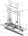
图1是本发明实施例一的构造示意图(套条没有套在沟槽挤压头上,第一压板和第二压板被活动把手下压向下翻平的状态);Figure 1 is a schematic diagram of the structure of Embodiment 1 of the present invention (the strip is not set on the groove extrusion head, the first pressing plate and the second pressing plate are pressed down by the movable handle and flattened);
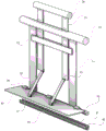
图2是本发明实施例一的构造示意图(套条没有套在沟槽挤压头上,第一压板和第二压板被活动把手提拉上翻的状态);Figure 2 is a schematic diagram of the structure of Embodiment 1 of the present invention (the strip is not set on the groove extrusion head, the first pressing plate and the second pressing plate are pulled up by the movable handle);
图3是本发明实施例一的套条没有套在沟槽挤压头上,拆除第二压板后,第一压板和被活动把手下压向下翻平的状态);Fig. 3 is the state that the first pressing plate and the first pressing plate are pushed down and flattened by the movable handle after the second pressing plate is removed without being set on the groove extrusion head in the first embodiment of the present invention);
图4是本发明实施例一附图1中A处的放大图;Fig. 4 is the enlarged view of place A in the accompanying drawing 1 of Embodiment 1 of the present invention;
图5是本发明实施例一附图1中B处的放大图;Figure 5 is an enlarged view at B in Figure 1 of Embodiment 1 of the present invention;
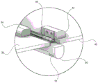
图6是本发明实施例一附图2中C处的放大图;Figure 6 is an enlarged view at C in Figure 2 of Embodiment 1 of the present invention;
图7是平整的铝皮放在预制保温板上准备加工的状态示意图;Fig. 7 is a schematic diagram of a state where a flat aluminum skin is placed on a prefabricated insulation board for processing;
图8是采用本发明对放在预制保温板上的铝皮进行沟槽挤压的示意图;Fig. 8 is the schematic diagram that adopts the present invention to carry out groove extrusion to the aluminum skin that is placed on the prefabricated insulation board;
图9是采用本发明对放在预制保温板上的铝皮进行沟槽挤压加工后,对两边的铝皮进行压平的示意图。Fig. 9 is a schematic diagram of flattening the aluminum skins on both sides after the aluminum skin placed on the prefabricated insulation board is grooved and extruded by the present invention.
图中:固定把手10、第一连杆11、限位横杆12、活动把手20、第二连杆21、第一压板30、第一压板下铰链31、第一交叉杆32、第一压板上铰链33、第一压板连接头34、挤压头第一铰链35、第二压板40、第二压板下铰链41、第二交叉杆42、第二压板上铰链43、第二压板连接头44、挤压头第二铰链45、沟槽挤压头50、第一磁块51、套条60、U型槽61、第二磁块62、预制保温板70、U型沟槽71、铝皮80、挤压成型的U型槽81。In the figure:
具体实施方式Detailed ways
下面,结合附图和实施例对本发明作进一步说明:如图1至图9所示,Below, the present invention will be further described in conjunction with accompanying drawings and embodiments: as shown in Fig. 1 to Fig. 9,
实施例一:一种为保温板的金属导热层压制直线沟槽的工具,包括固定把手10、活动把手20、第一压板30、第二压板40、沟槽挤压头50、套条60;其特征在于:所述固定把手10下面设置有第一连杆11和限位横杆12;第一连杆11下面设置有沟槽挤压头50,直线沟槽挤压头50上设置有挤压头第一铰链35和挤压头第二铰链45;挤压头第一铰链35与第一压板30上的第一压板连接头34转动连接;挤压头第二铰链45与第二压板40上的第二压板连接头44转动连接;第一压板30上设置有第一压板下铰链31,第一压板30通过第一压板下铰链31与第一交叉杆32的下端转动连接;第一交叉杆32的上端设置有第一压板上铰链33;第一交叉杆32与第二连杆21通过第一压板上铰链33转动连接;第二压板40上设置有第二压板下铰链41,第二压板40通过第二压板下铰链41与第二交叉杆42的下端转动连接;第二交叉杆42的上端设置有第二压板上铰链44;第二交叉杆42与第二连杆21之间通过第二压板上铰链44转动连接;第二连杆21的上端设置有活动把手20;所述沟槽挤压头50、的两端下方设置有第一磁块51;所述套条60上设置有U型槽61,U型槽61的两端设置有第二磁块62;所述套条60上的U型槽61与沟槽挤压头50的大小、形状及长度相匹配。Embodiment 1: A tool for pressing linear grooves for metal heat-conducting laminates of insulation boards, including a
所述U型槽61套在沟槽挤压头50的下方并两头对齐时,第一磁块51与第二磁块62会吸附在一起。When the
所述沟槽挤压头50采用金属制作。The
第一压板30、第一交叉杆32、第二压板40和第二交叉杆42和第一连杆11、限位横杆12采用金属板材制作。The first
所述固定把手10、活动把手20和第二连杆21采用工程塑料制作;所述套条60采用具有弹性的工程塑料制作。The
所述沟槽挤压头50的长度尺寸是600mm,宽度尺寸是16mm,高度尺寸是16mm;所述套条60的长度尺寸是600mm,宽度尺寸是20mm,高度尺寸是20mm。The
在本实施例中,套条60能够轻易地套在沟槽挤压头50的下方,在两头对齐后,第一磁块51与第二磁块62会相互吸引并吸附在一起,二者之间的垂直吸附力大于10公斤。In this embodiment, the
套条60中的U型槽61光滑平顺;沟槽挤压头50的下方光滑平顺,套条60套在沟槽挤压头50的下方,第一磁块51与第二磁块62相互吸引在一起后,将套条60顺着沟槽挤压头50长度的方向推移,将互吸引在一起的磁铁位置平移错开后,可轻松地将套条60从沟槽挤压头50上拆卸下来。The U-shaped
实施例二:实施例二与实施例一的区别在于,限位横杆12与第二连杆21固定在一起,限位横杆12与第一连杆11之间呈滑动夹持关系,在限位横杆12与固定把手10之间设置一拉簧,在拉簧的作用下,第一压板30与第二压板40会自动保持上翻的状态,便于使用者对沟槽进行压制。Embodiment 2: The difference between Embodiment 2 and Embodiment 1 is that the
本发明的上述实施例是为说明本发明所列举的典型实施方式,而不是对本发明的实施方式所作的限定。由本发明实施例的提示所引申出的明显的变化方式仍处于本发明的权利保护范围当中。The above-mentioned embodiments of the present invention are for illustrating typical implementations of the present invention, rather than limiting the implementation of the present invention. The obvious changes derived from the hints of the embodiments of the present invention are still within the protection scope of the present invention.
Claims (8)
Priority Applications (1)
| Application Number | Priority Date | Filing Date | Title |
|---|---|---|---|
| CN202210307285.8A CN114570814B (en) | 2022-03-27 | 2022-03-27 | Tool for laminating metal heat conduction layer of heat insulation plate into linear groove |
Applications Claiming Priority (1)
| Application Number | Priority Date | Filing Date | Title |
|---|---|---|---|
| CN202210307285.8A CN114570814B (en) | 2022-03-27 | 2022-03-27 | Tool for laminating metal heat conduction layer of heat insulation plate into linear groove |
Publications (2)
| Publication Number | Publication Date |
|---|---|
| CN114570814A CN114570814A (en) | 2022-06-03 |
| CN114570814B true CN114570814B (en) | 2023-06-27 |
Family
ID=81776248
Family Applications (1)
| Application Number | Title | Priority Date | Filing Date |
|---|---|---|---|
| CN202210307285.8A Expired - Fee Related CN114570814B (en) | 2022-03-27 | 2022-03-27 | Tool for laminating metal heat conduction layer of heat insulation plate into linear groove |
Country Status (1)
| Country | Link |
|---|---|
| CN (1) | CN114570814B (en) |
Citations (17)
| Publication number | Priority date | Publication date | Assignee | Title |
|---|---|---|---|---|
| US3030879A (en) * | 1960-04-25 | 1962-04-24 | Republic Die & Tool Company | Press |
| JP2001001007A (en) * | 1999-06-15 | 2001-01-09 | Hitachi Cable Ltd | Manufacturing method of perforated foil |
| KR20020080765A (en) * | 2001-04-17 | 2002-10-26 | 주식회사 우리 | Method For Manufacturing The Embossing Plate For bomb |
| KR20090121479A (en) * | 2008-05-22 | 2009-11-26 | 백성현 | Metal V Groove Press Machine |
| CN104325022A (en) * | 2013-06-28 | 2015-02-04 | 吴红平 | Stamping mould with capability of protecting personnel security and braking function |
| WO2015053036A1 (en) * | 2013-10-09 | 2015-04-16 | 新日鐵住金株式会社 | Production method for press-molded body, and press molding device |
| CN105718083A (en) * | 2016-02-14 | 2016-06-29 | 重庆工业职业技术学院 | Using-angle-adjustable mouse capable of preventing hand fatigue |
| CN209452587U (en) * | 2019-01-19 | 2019-10-01 | 西安北方惠安防化设备有限公司 | Molding presses for forming handle mounts |
| CN210334002U (en) * | 2019-07-04 | 2020-04-17 | 福建省中友俊建材科技有限公司 | Aluminum template pressing plate convenient to use |
| CN111319082A (en) * | 2020-02-28 | 2020-06-23 | 张永强 | A geothermal slotting machine |
| CN211218288U (en) * | 2019-11-22 | 2020-08-11 | 唐山孚达建筑材料有限公司 | Floor heating panel pipe slot aluminium foil indent device |
| CN212644737U (en) * | 2020-05-11 | 2021-03-02 | 广州孚达保温隔热材料有限公司 | Novel high-strength environment-friendly dry-type floor heating plate |
| CN214302680U (en) * | 2020-12-17 | 2021-09-28 | 唐山孚达建筑材料有限公司 | Prefabricated type arc groove floor heating module plate |
| CN214768080U (en) * | 2020-12-17 | 2021-11-19 | 唐山孚达建筑材料有限公司 | Warm up module board aluminium foil laminated groove device |
| CN113681929A (en) * | 2021-08-30 | 2021-11-23 | 廊坊皓思新能源科技有限公司 | Assembled floor heating module and preparation method thereof |
| CN113733707A (en) * | 2021-09-06 | 2021-12-03 | 重庆市炙热科技发展有限公司 | Using method of equipment for paving aluminum foil for curved groove heat-insulation board |
| CN114192663A (en) * | 2021-12-08 | 2022-03-18 | 嘉兴职业技术学院 | Continuous rolling equipment of metal foil area |
Family Cites Families (1)
| Publication number | Priority date | Publication date | Assignee | Title |
|---|---|---|---|---|
| DE2937204C2 (en) * | 1979-09-14 | 1982-09-02 | Werner & Pfleiderer, 7000 Stuttgart | Extruder machine with wide die head and associated calender |
-
2022
- 2022-03-27 CN CN202210307285.8A patent/CN114570814B/en not_active Expired - Fee Related
Patent Citations (17)
| Publication number | Priority date | Publication date | Assignee | Title |
|---|---|---|---|---|
| US3030879A (en) * | 1960-04-25 | 1962-04-24 | Republic Die & Tool Company | Press |
| JP2001001007A (en) * | 1999-06-15 | 2001-01-09 | Hitachi Cable Ltd | Manufacturing method of perforated foil |
| KR20020080765A (en) * | 2001-04-17 | 2002-10-26 | 주식회사 우리 | Method For Manufacturing The Embossing Plate For bomb |
| KR20090121479A (en) * | 2008-05-22 | 2009-11-26 | 백성현 | Metal V Groove Press Machine |
| CN104325022A (en) * | 2013-06-28 | 2015-02-04 | 吴红平 | Stamping mould with capability of protecting personnel security and braking function |
| WO2015053036A1 (en) * | 2013-10-09 | 2015-04-16 | 新日鐵住金株式会社 | Production method for press-molded body, and press molding device |
| CN105718083A (en) * | 2016-02-14 | 2016-06-29 | 重庆工业职业技术学院 | Using-angle-adjustable mouse capable of preventing hand fatigue |
| CN209452587U (en) * | 2019-01-19 | 2019-10-01 | 西安北方惠安防化设备有限公司 | Molding presses for forming handle mounts |
| CN210334002U (en) * | 2019-07-04 | 2020-04-17 | 福建省中友俊建材科技有限公司 | Aluminum template pressing plate convenient to use |
| CN211218288U (en) * | 2019-11-22 | 2020-08-11 | 唐山孚达建筑材料有限公司 | Floor heating panel pipe slot aluminium foil indent device |
| CN111319082A (en) * | 2020-02-28 | 2020-06-23 | 张永强 | A geothermal slotting machine |
| CN212644737U (en) * | 2020-05-11 | 2021-03-02 | 广州孚达保温隔热材料有限公司 | Novel high-strength environment-friendly dry-type floor heating plate |
| CN214302680U (en) * | 2020-12-17 | 2021-09-28 | 唐山孚达建筑材料有限公司 | Prefabricated type arc groove floor heating module plate |
| CN214768080U (en) * | 2020-12-17 | 2021-11-19 | 唐山孚达建筑材料有限公司 | Warm up module board aluminium foil laminated groove device |
| CN113681929A (en) * | 2021-08-30 | 2021-11-23 | 廊坊皓思新能源科技有限公司 | Assembled floor heating module and preparation method thereof |
| CN113733707A (en) * | 2021-09-06 | 2021-12-03 | 重庆市炙热科技发展有限公司 | Using method of equipment for paving aluminum foil for curved groove heat-insulation board |
| CN114192663A (en) * | 2021-12-08 | 2022-03-18 | 嘉兴职业技术学院 | Continuous rolling equipment of metal foil area |
Non-Patent Citations (1)
| Title |
|---|
| 网络化制造模式下基于语义网的协同产品配置模型研究;汤华茂;柏占伟;董元发;;机械设计与制造(第08期);第274-276页 * |
Also Published As
| Publication number | Publication date |
|---|---|
| CN114570814A (en) | 2022-06-03 |
Similar Documents
| Publication | Publication Date | Title |
|---|---|---|
| CN202023314U (en) | Metal decorative board with heating structure | |
| CN114570814B (en) | Tool for laminating metal heat conduction layer of heat insulation plate into linear groove | |
| CN113696594B (en) | A device for laying aluminum foil for curved groove insulation board | |
| CN113733707B (en) | Using method of equipment for paving aluminum foil for curved groove heat-insulation board | |
| CN119175769B (en) | Forming process of photovoltaic power generation integrated heat-preservation environment-friendly wallboard | |
| CN103899064B (en) | Thermal-insulating type fireproof decoration plate | |
| CN113696312A (en) | Method for paving aluminum foil on prefabricated curve groove concrete insulation board | |
| CN114482307A (en) | Method for arranging aluminum skin heat conduction layer on curved groove heat insulation plate | |
| CN222685777U (en) | Thermal insulation rock wool sandwich composite board | |
| CN210482643U (en) | A sandwich thermal insulation precast concrete external wall panel | |
| CN210507968U (en) | A thermal insulation type unit curtain wall | |
| CN114589226A (en) | A method of using a tool for pressing a straight groove for a heat-conducting layer of a thermal insulation board | |
| CN114535378A (en) | Equipment for extruding aluminum skin heat-conducting layer for straight line groove heat-insulating plate | |
| CN108005263A (en) | Bolt type connecting piece for prefabricated heat-insulating wall | |
| CN114589226B (en) | A method for using a tool to press straight grooves into the thermal conductive layer of an insulation board. | |
| CN204850102U (en) | High -efficient heat preservation heat insulating board | |
| CN203808271U (en) | Prefabricated heat-preservation wallboard | |
| CN202731092U (en) | Environment-friendly insulation plate of asbestos cement board and foam | |
| CN202416599U (en) | Rock wool sandwich plate | |
| CN208023782U (en) | Bolt type connecting piece for prefabricated heat-insulating wall | |
| CN205558110U (en) | Heat insulation decorative panel | |
| CN222949304U (en) | Composite building block | |
| CN220184498U (en) | Heat preservation wallboard with sound insulation function | |
| CN220353296U (en) | Self-heating panel for smart home | |
| CN221236310U (en) | A kind of assembled wall panel with thermal insulation and broken bridge |
Legal Events
| Date | Code | Title | Description |
|---|---|---|---|
| PB01 | Publication | ||
| PB01 | Publication | ||
| SE01 | Entry into force of request for substantive examination | ||
| SE01 | Entry into force of request for substantive examination | ||
| TA01 | Transfer of patent application right | ||
| TA01 | Transfer of patent application right |
Effective date of registration: 20230601 Address after: No. 1000 Taoyuan Avenue, Yubei District, Chongqing Applicant after: CHONGQING INDUSTRY POLYTECHNIC College Address before: 16-7, 142 Jiefang West Road, Yuzhong District, Chongqing 400012 Applicant before: Chongqing heat source technology development Co.,Ltd. |
|
| GR01 | Patent grant | ||
| GR01 | Patent grant | ||
| CP03 | Change of name, title or address | ||
| CP03 | Change of name, title or address |
Address after: 401120 Taoyuan Road, Chongqing, No. 1000, No. Patentee after: Chongqing Industrial Vocational and Technical University Country or region after: China Address before: 401120 Taoyuan Road, Chongqing, No. 1000, No. Patentee before: CHONGQING INDUSTRY POLYTECHNIC College Country or region before: China |
|
| CF01 | Termination of patent right due to non-payment of annual fee | ||
| CF01 | Termination of patent right due to non-payment of annual fee |
Granted publication date: 20230627 |