Background
DE 29618489U 1 shows a device for converting and/or transmitting optical and/or electrical signals, with a connection module for connection to an optical and/or electrical line network and with an application module which can be coupled to the connection module in various angular positions, wherein the connection module has a substantially square-bottomed housing which is provided on the top side facing the application module with a mounting plate which projects substantially uniformly beyond the housing on all sides and has symmetrically arranged fastening elements for fastening the connection module, wherein the mounting plate is constructed as a printed circuit board with a pin header (stifleitten) for insertion on the application module.
EP 2783423B 1 shows a housing in which an electronic printed circuit board is embedded, wherein the electronic printed circuit board comprises a plurality of electrical connections. The electrical connection may be made through a connector receptacle in the housing.
In this case, the electrical connections of the printed circuit board must be geometrically related to the connector sockets of the housing. Thus, the configuration or design of the printed circuit board is limited.
The german patent and trademark office retrieves the following prior art in the priority application of the present application: DE 29618489U 1.
Disclosure of Invention
The object of the invention is to propose an electronic system for industrial environments that can be used flexibly.
This object is solved by the subject matter of independent claim 1.
Advantageous embodiments of the invention are specified in the dependent claims and the following description.
The system according to the invention essentially comprises a housing with at least one exchangeable side. The housing is preferably configured as a cuboid, but not as a cube. A printed circuit board, which may be a main component of an electronic component not described in detail, is arranged in the housing. For example, it is a sensor system here. The printed circuit board is then equipped with corresponding components, in particular sensors. Furthermore, the system comprises at least one functional element, which in particular forms an insertion interface for a printed circuit board or an electronic component.
The functional element advantageously comprises a plug connector or a plug connector socket, for example a USB socket. However, the functional element may also have an optical display unit, for example an LED display. The display unit may then, for example, make the status of the system or device visible.
An opening is provided in at least one of the replaceable sides of the housing, the opening being associated with an electrical connection of the printed circuit board. This means that the electrical connections of the printed circuit board can be accessed through the opening. At least one functional element can be inserted into the housing through a corresponding opening in the side and connected to the electrical connections of the printed circuit board in each case.
Printed circuit boards typically include electronic circuitry. The circuit usually comprises various sensors electrically connected to a control and evaluation unit. The electrical connections of the printed circuit board may also be considered as interfaces to electronic components. The functional elements then form in particular a corresponding plug-in interface for the electronic components. The system according to the invention can thus be integrated, for example, into higher-level systems, in particular machines or industrial installations.
The housing preferably has two to four replaceable sides and at least two fixed sides. In the aforementioned rectangular parallelepiped shape, the two fastening sides are the large sides (broad sides), while the two to four exchangeable sides form the smaller sides (narrow sides).
The printed circuit board has a rectangular basic shape. Electrical connections for functional elements are provided on the edge side of the printed circuit board. The electrical connections each comprise a plurality of electrically conductive contact foils applied to the printed circuit board
These contact foils are in turn conductively connected to the printed conductors of the printed circuit board. The number of contact lamellae typically corresponds to the number of contact elements of the associated functional element. The connection side of the contact element is pressed, for example, in an electrically conductive manner onto the corresponding contact foil.
The functional elements preferably each have an axial groove on the connection side, which overlaps or surrounds the associated electrical connection of the printed circuit board. Advantageously, the width of the axial slot is slightly smaller than the thickness of the printed circuit board, so that the above-mentioned pressing takes place between the connection side of the contact element and the contact foil. The connection side of the contact element is pressed onto the associated contact foil, whereby a secure electrically conductive connection is established.
Advantageously, the exchangeable side faces each have a different number of openings. The number and position of the openings correspond to the number and position of the electrical connections of the printed circuit board, which are aligned with the respective side faces. Depending on the side and the number of openings located therein, the system can be adapted to different circuit board designs.
The housing preferably comprises a base frame already having fixed sides (broad sides). Different, exchangeable sides can be fastened to the base frame as required. The fastening may be accomplished, for example, by a threaded connection.
In an advantageous embodiment of the invention, the exchangeable side of the housing has fastening means on the outside, by means of which the housing can be fastened to a retaining profile, for example a mounting rail. A plurality of systems according to the invention with different electronic components can thus be arranged side by side, for example on a mounting rail.
Preferably, a recess is introduced in each of the two opposite side faces. The grooves are oriented parallel to each other. The width of the respective groove corresponds substantially to the thickness of the printed circuit board. The printed circuit board may be pushed into the recess, thereby securely holding the printed circuit board in the system. The recess extends approximately in the center of the respective side face, so that the printed circuit board has the same distance from the side walls parallel thereto, respectively. The printed circuit board in the industrial environment can thus be mechanically protected, in particular against vibrations.
Desirably, the housing and/or at least one side is made of aluminum. This material is both light and strong. However, compared to plastic housings, they have sufficient electrical conductivity so that the printed circuit board or components mounted thereon can also be grounded if necessary.
Detailed Description
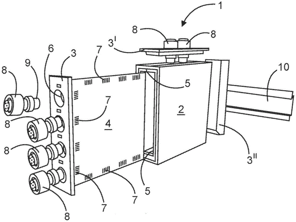
Fig. 1 shows an exploded view of a system 1 according to the invention. The system 1 shown here comprises a housing 2 with two fixed sides and four exchangeable sides 3, wherein three of these exchangeable sides 3, 3', 3 "are shown spaced apart from the housing 2 for illustration purposes.
A printed circuit board 4 is provided in the housing 2. The printed circuit board 4 is pushed into the housing 2 in recesses 5 formed in two opposite side walls and is thereby held. The replaceable side walls 3, 3' each contain a different number of openings 6. The openings 6 are associated with electrical connections 7 assigned to them, which are arranged circumferentially on the printed circuit board 4 on the edge side.
The functional element 8 is connected to the electrical connection 7. The functional elements 8 comprise contact elements, which are not shown in the figures for illustrative reasons. The functional elements 8 each have a groove 9 on the connection side. The corresponding connection area of the contact element is positioned in this groove 9. The connection regions of the contact elements are brought into electrically conductive contact with the contact lamellae 11 of the respective electrical connection 7 by pushing the printed circuit board 4 into the grooves 9 of the functional elements 8. A particularly simple assembly of the system 1 can thereby be achieved. The functional element 8 has a surrounding seal which protects the opening or the system against the ingress of media (water, dust, etc.).
The exchangeable side 3 "is provided with fastening means on the outside for mounting the rail 10. Thus, the system can be arranged on the mounting rail 10 together with other components. This is particularly advantageous for large industrial installations or control cabinets.
Fig. 2 shows a printed circuit board 4 that can be used in the system 1 according to the invention. The printed circuit board 4 has a rectangular, in this case even square, basic shape. The printed circuit board 4 is essentially divided into three functional units 4a, 4b and 4 c. The first functional unit 4a represents a communication interface. This enables data exchange of the system, for example with a higher level system. The second functional unit 4b of the printed circuit board 4 comprises the basic components of the system 1. This is, for example, a sensor circuit. The printed circuit board 4 or the entire system 1 is supplied with the necessary energy (current) via the third functional unit 4 c.
Electrical connections 7 for functional components 8 are arranged on three edge sides of the printed circuit board 4. The electrical connection portions 6 respectively include a plurality of contact sheets 11. Which are each electrically conductively connected to at least one printed conductor of the printed circuit board 4 (not shown for illustrative reasons).
List of reference numerals
1 System
2 casing
3 replaceable side surface
4 printed circuit board
5 groove
6 opening
7 electric connection part
8 functional element
9 groove
10 mounting rail
11 contact sheet