CN114709012A - Novel anti-overload FFC cable and preparation method thereof - Google Patents
Novel anti-overload FFC cable and preparation method thereof Download PDFInfo
- Publication number
- CN114709012A CN114709012A CN202210285281.4A CN202210285281A CN114709012A CN 114709012 A CN114709012 A CN 114709012A CN 202210285281 A CN202210285281 A CN 202210285281A CN 114709012 A CN114709012 A CN 114709012A
- Authority
- CN
- China
- Prior art keywords
- cable
- heat
- conductor
- shrinkable
- piece
- Prior art date
- Legal status (The legal status is an assumption and is not a legal conclusion. Google has not performed a legal analysis and makes no representation as to the accuracy of the status listed.)
- Granted
Links
Images


Classifications
-
- H—ELECTRICITY
- H01—ELECTRIC ELEMENTS
- H01B—CABLES; CONDUCTORS; INSULATORS; SELECTION OF MATERIALS FOR THEIR CONDUCTIVE, INSULATING OR DIELECTRIC PROPERTIES
- H01B7/00—Insulated conductors or cables characterised by their form
- H01B7/08—Flat or ribbon cables
-
- H—ELECTRICITY
- H01—ELECTRIC ELEMENTS
- H01B—CABLES; CONDUCTORS; INSULATORS; SELECTION OF MATERIALS FOR THEIR CONDUCTIVE, INSULATING OR DIELECTRIC PROPERTIES
- H01B13/00—Apparatus or processes specially adapted for manufacturing conductors or cables
-
- H—ELECTRICITY
- H01—ELECTRIC ELEMENTS
- H01B—CABLES; CONDUCTORS; INSULATORS; SELECTION OF MATERIALS FOR THEIR CONDUCTIVE, INSULATING OR DIELECTRIC PROPERTIES
- H01B7/00—Insulated conductors or cables characterised by their form
- H01B7/42—Insulated conductors or cables characterised by their form with arrangements for heat dissipation or conduction
- H01B7/428—Heat conduction
Landscapes
- Engineering & Computer Science (AREA)
- Manufacturing & Machinery (AREA)
- Insulated Conductors (AREA)
Abstract
The invention relates to the technical field of wire harnesses, in particular to a novel overload-proof FFC cable, which comprises a cable main body, wherein a flat conductor is arranged in the cable main body, and the flat conductor comprises a front-section conductor and a rear-section conductor; the cable comprises a cable body, a front-section conductor, a rear-section conductor, a heat-shrinkable part, a heating part, a free heat-shrinkable part, a cover film and a cable body, wherein the cable body is movably provided with the conducting part, the conducting part is connected with the front-section conductor and the rear-section conductor in a bridging mode, the heat-shrinkable part is arranged on the conducting part, the rear-section conductor is provided with the heating part, the heating part is in mapping superposition with the free heat-shrinkable part of the heat-shrinkable part, and the cable body is combined with the cover film at the position covered by the conducting part and the heat-shrinkable part; the invention utilizes the thermal shrinkage of the thermal shrinkage piece to drive the conducting piece to act to disconnect the cable, thereby avoiding the transition heating caused by overload and improving the safety during overload protection.
Description
Technical Field
The invention relates to the technical field of wire harnesses, in particular to a novel overload-proof FFC cable and a preparation method of the cable.
Background
The FFC flexible flat cable can select the number and the spacing of the conducting wires at will, so that the connection is more convenient, the volume of an electronic product is greatly reduced, the production cost is reduced, the production efficiency is improved, and the FFC flexible flat cable is most suitable for being used as a data transmission cable between a moving part and a main board, between a PCB and a small-sized electrical equipment and is successfully applied to a plurality of high-end equipment.
In some application scenarios, for example, a new energy automobile battery management system requires that its internal cable has an overload protection function, in the prior art, a fuse is generally used as a protection component, and the fuse is fused when the cable is overloaded, so as to protect the whole machine.
In the existing FFC cable with fuse, it is more conventional to directly form a fusing structure with reduced overcurrent cross-sectional area on the flat conductor, for example, the FFC disclosed in CN210378535U with fusing protection function, holes or notches penetrating through the front and rear end faces of the conductor are manufactured by punching to reduce the overcurrent area of the fusing part, when the flowing current is too large, the heat generated by the fusing part is too large, which leads to fusing of the fusing part, and the conductor is broken and is no longer electrified; in other prior art, overload protection can also be achieved by adding a patch fuse.
However, no matter the fuse part or the patch fuse is formed by punching, a large amount of heat is generated in the fusing process, and then an external insulating layer is burnt, so that the adjacent cable is affected and cannot work continuously, and a great loss is caused even if the whole machine is seriously or even ignited.
Disclosure of Invention
In view of the above, an object of the present invention is to overcome the defects in the prior art, and provide a novel anti-overload FFC cable, in which the thermal shrinkage of the thermal shrinkage member is used to drive the conducting member to act to disconnect the cable, so as to avoid excessive heating caused by overload, and improve safety during overload protection.
The novel overload-proof FFC cable comprises a cable main body, wherein a flat conductor is arranged in the cable main body, the flat conductor comprises a front section conductor and a rear section conductor, and an insulation gap is formed between the front section conductor and the rear section conductor; the cable comprises a cable body and is characterized in that a conducting part is movably arranged at the position of an insulation gap, the conducting part is connected with a front-section conductor and a rear-section conductor in a bridging mode, a heat-shrinkable part is arranged on the conducting part, the heat-shrinkable part extends backwards from the conducting part and is fixed with the rear-section conductor after a free heat-shrinkable part is formed, a heating part is formed on the rear-section conductor, the heating part is mapped and superposed with the free heat-shrinkable part of the heat-shrinkable part, and covering films are combined at the positions, covered by the conducting part and the heat-shrinkable part, of the cable body.
Further, the heat generating portion is formed by forming a notch in the width direction of the conductor or forming an excessively thin spot in the thickness direction.
Further, the conducting piece is of a hard sheet structure, the heat-shrinkable piece is of a strip structure made of heat-shrinkable materials, the heat-shrinkable piece covers the conducting piece, a lower step is formed at the rear end edge of the conducting piece, an upper step is formed at the rear position of the rear end conductor close to the lower step, and an openable window is formed in the cover film.
Further, the cover film comprises an upper film and a lower film, the lower film forms a covering fin which can be opened at a position corresponding to the conducting piece, the size of the covering fin is larger than that of the conducting piece, an exposing hole is formed in the position corresponding to the covering fin of the upper film, and the size of the exposing hole is equivalent to that of the conducting piece.
Furthermore, the flat conductors are multiple, and the conduction pieces and the thermal shrinkage pieces corresponding to different flat conductors are independent of each other.
The invention also provides a preparation method of the novel overload-proof FFC cable, which comprises the following steps:
(1) formation of cable bodies
(1-1) rolling the raw materials of the conducting wires to form a flat conductor, forming a heating part with a small overcurrent sectional area on the flat conductor, and hot-pressing and attaching an insulating layer to form a cable main body;
(1-2) windowing the cable main body to expose a part of the flat conductor;
(1-3) etching the exposed part of the opening window of the flat conductor to break the flat conductor;
(2) formation of protective assemblies
(2-1), combining the metal with the length and the size smaller than that of the heat-shrinkable layer on the heat-shrinkable layer, and cutting to form a strip-shaped protective element with the width approximately equal to that of the flat conductor, wherein the front end of the formed strip-shaped protective element is provided with a conducting piece, and the rear end of the formed strip-shaped protective element extends out of a part of the heat-shrinkable piece;
(2-2) combining the rear end part of the heat shrinkable piece of the strip-shaped protection element with the covering film, and reserving a part of the heat shrinkable piece before a combination point to be separated from the covering film;
(3) combination of
(3-1), the covering film with the strip-shaped protection element is attached to the windowing position of the cable main body, the separated part of the heat shrinkage piece and the covering film covers the heating part, and the conducting piece is pressed and connected with the cut-off position of the flat conductor.
Further, the heating part is formed by pressing a bulge on the surface of the pressing wheel in the rolling process or formed by cutting the cutting edge.
Furthermore, in the rolling process, the surface of the pressing wheel is provided with a depression, a flat conductor formed by rolling is provided with a raised upper step, a strip-shaped protection element formed by combining and cutting the sheet metal and the heat-shrinkable layer is provided with a lower step, the upper step and the lower step are matched, and the used covering film is provided with a window at the position corresponding to the conducting piece.
Further, the covering film is of a double-layer structure, an exposure hole is formed in the upper layer film, the size of the exposure hole is equivalent to that of the conduction piece, the lower layer film forms a covering fin, and the size of the covering fin is larger than that of the conduction piece.
Furthermore, the cable main body is provided with a plurality of flat conductors, and the flat conductors arranged side by side are exposed when the window is opened; arranging a plurality of independent strip-shaped protection elements on one covering film side by side, wherein when the covering films are combined, the strip-shaped protection elements correspond to the flat conductors one by one
The invention has the beneficial effects that: the invention discloses a novel anti-overload FFC cable, which utilizes a heating part formed on a flat conductor to generate certain heat, the heat promotes a heat shrinkage piece covered on the flat conductor to generate heat shrinkage, and the heat shrinkage piece drives a conducting piece to deviate, so that overload current passing through the flat conductor is cut off.
Drawings
The invention is further described below with reference to the following figures and examples:
FIG. 1 is a schematic structural view of example 1 of the present invention;
FIG. 2 is a schematic structural diagram of example 2 of the present invention;
FIG. 3 is a schematic structural diagram of the cover film in this embodiment 2;
fig. 4 is a top view of the present invention.
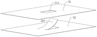
Description of reference numerals: a cable main body 1; a flat conductor 11; an upper insulating layer 12; a lower insulating layer 13; a heat generating portion 14; a cover film 2; an upper film 21; an exposure hole 211; an underlayer film 22; the cover flap 221; a conducting member 3; a heat shrinkable member 4; a free heat-shrinkable portion 41; steps 31, 32.
Detailed Description
The technical solutions in the embodiments of the present invention will be clearly and completely described below, and it is obvious that the described embodiments are only a part of the embodiments of the present invention, and not all embodiments. All other embodiments, which can be derived by a person skilled in the art from the embodiments given herein without making any creative effort, shall fall within the protection scope of the present invention.
Example 1
The preparation method of novel overload-proof FFC cable in this embodiment, at first press into the flat conductor 11 of appointed specification with a plurality of circular cross section copper conductors through the calender, place the insulating layer respectively on two hot pinch rollers of FFC rigging machine as flat cable upper insulation layer 12 and lower insulating layer 13, this hot pinch roller will scribble the upper insulation layer 12 of sol, lower insulating layer 13 and the flat conductor 11 that is located between heat the pressurization and roll through the wheel and bond together and become cable main part 1, this insulating layer is preferred PI material promptly polyimide material, high temperature resistant, be one of the best organic polymer material of comprehensive properties, in some conventional production, still can include processes such as secondary hot pressing, give unnecessary detail here.
In the calendering process, the adopted pressing wheel is provided with a convex part at a specific position, so that an over-thin point which is subjected to excessive pressure is formed on the flat conductor 11 in the calendering process, and the heat generated by the over-thin point under normal load is in a normal range through the size design of the over-thin point.
Before the insulation layer is hot-pressed, the insulation layer may be punched to make the obtained cable body 1 have a window to expose a portion of the flat conductor 11, and the heating portion 14 with an excessively thin point is located on the exposed portion. By enlarging the size of the opening, the plurality of flat conductors 11 are exposed simultaneously.
The exposed flat conductor 11 is etched to be broken into two independent sections, and an insulation gap is formed between the two sections, so that the two sections cannot be conducted by themselves.
In this embodiment, overload protection is performed on a protection component attached to a fenestration site, specifically, the protection component includes three parts, namely a cover film 2, a conducting piece 3 and a heat shrinkable piece 4, the conducting piece 3 is a metal sheet, the heat shrinkable piece 4 is a heat shrinkable piece, the metal sheet with the length smaller than that of the heat shrinkable piece is bonded to the heat shrinkable piece, and then the metal sheet is cut along the width direction, so that a strip-shaped protection element can be formed, the front end part of the formed strip-shaped protection element can be used for current conduction due to the metal, the rear end part shrinks when being heated, a plurality of strip-shaped protection elements are bonded to the cover film 2 with a large area side by side at intervals, and during bonding, a part of the strip-shaped protection element is left in a separated state by cotton bonding the rear end part of the heat shrinkable piece 4 to the cover film 2, which is called a free heat shrinkable part 41.
The cover film 2 with the strip-shaped protection elements is attached to the windowing position of the cable body 1, the strip-shaped protection elements correspond to the flat conductors 11, the separated parts of the heat shrinkable member 4 and the cover film 2 cover the heating part 14, and the conducting member 3 is pressed to conduct the cut-off part of the flat conductors 11.
It is worth mentioning that when the cover film 2 is combined, only the outer edge portion of the cover film 2 is combined with the cable main body 1, as shown in fig. 4, to avoid affecting the contraction movement of the strip-shaped protection element inside.
In a further improvement, the windows corresponding to each flat conductor 11 are not connected into a sheet, but are independently opened, an insulating layer with a certain width is reserved between adjacent windows, and when the cover film 2 is combined, the cover film 2 is combined with the insulating layer between the adjacent windows, so that the lateral deviation of the strip-shaped protection element is limited.
As shown in fig. 1, the conduction part 3 conducted in a transition manner is communicated with the front-stage conductor and the rear-stage conductor, when overload occurs, heat generated by the heating part 14 exceeds a normal state, the free heat shrinkage part 41 attached to the heating part contracts to drive the conduction part 3 to move backwards until the conduction part is completely separated from the front-stage conductor, and therefore the effects of current shutoff and circuit protection are achieved.
Certain gaps are formed between the adjacent strip-shaped protection elements and are mutually independent.
Example 2
The method comprises the steps of firstly pressing a plurality of copper conductors with circular sections into flat copper conductors with specified specifications through a calender, respectively placing insulating layers on two hot pressing wheels of an FFC laminating machine to serve as an upper insulating layer 12 and a lower insulating layer 13 of a flat cable, heating and pressurizing the upper insulating layer 12 coated with sol, the lower insulating layer 13 and the flat conductors 11 positioned between the upper insulating layer and the lower insulating layer by the hot pressing wheels and rolling and bonding the upper insulating layer and the lower insulating layer and the flat conductors 11 together into a cable main body 1 through wheels, and when the flat conductors are calendered, cutting edges for cutting the flat conductors 11 into gaps are formed on the pressing wheels in a molding mode, so that the width of the flat conductors 11 is reduced, and more heat is generated when the flat conductors are overloaded.
In addition, the press wheel has a depression, and the flat conductor 11 is formed with a step 31.
In the embodiment, a metal sheet with a length smaller than that of the heat shrinkable sheet is bonded on the heat shrinkable sheet, and then is slit along the width direction to form the strip-shaped protection element, the step 32 formed by the edge of the conducting piece 3 is arranged on the lower surface of the strip-shaped protection element, and when the strip-shaped protection element is assembled on the cable main body 1, the two steps 31 and 32 are fitted with each other.
After the protection component and the cable body 1 are combined, when overload occurs, the heat shrinkage piece 4 is heated and shrunk, the conduction piece 3 is limited by the step 31 on the flat conductor 11, and cannot move backwards as in the embodiment 1, but moves upwards, so that power failure protection is realized.
Specifically, the cover film 2 that this embodiment adopted does cover film 2 is bilayer structure, and the exposure hole 211 has been seted up to upper film 21, and the size of exposure hole 211 is equivalent to leading to piece 3, and lower film 22 forms and covers fin 221, the size that covers fin 221 is greater than lead to piece 3, cover film 2 laminating back on cable main part 1, upper film 21 covers lower film 22, covers fin 221 and can not lift by oneself, plays the circuit protection effect, and the effect that only can warp in inside leads to piece 3 is lifted.
Fig. 2-3 show the flat cable obtained in this embodiment, and the remaining parts not described in this embodiment may adopt the prior art or be the same as those in embodiment 1, and are not described again here.
Finally, the above embodiments are only for illustrating the technical solutions of the present invention and not for limiting, although the present invention has been described in detail with reference to the preferred embodiments, it should be understood by those skilled in the art that modifications or equivalent substitutions may be made to the technical solutions of the present invention without departing from the spirit and scope of the technical solutions of the present invention, and all of them should be covered in the claims of the present invention.
Claims (10)
1. A novel anti-overload FFC cable comprises a cable main body, wherein a flat conductor is arranged in the cable main body, and the novel anti-overload FFC cable is characterized in that: the flat conductor comprises a front section conductor and a rear section conductor, and an insulation gap is formed between the front section conductor and the rear section conductor; the cable comprises a cable body and is characterized in that a conducting part is movably arranged at the position of an insulation gap, the conducting part is connected with a front-section conductor and a rear-section conductor in a bridging mode, a heat-shrinkable part is arranged on the conducting part, the heat-shrinkable part extends backwards from the conducting part and is fixed with the rear-section conductor after a free heat-shrinkable part is formed, a heating part is formed on the rear-section conductor, the heating part is mapped and superposed with the free heat-shrinkable part of the heat-shrinkable part, and covering films are combined at the positions, covered by the conducting part and the heat-shrinkable part, of the cable body.
2. The novel anti-overload FFC cable of claim 1, wherein: the heat generating portion is formed by forming a notch in the width direction of the conductor or forming an excessively thin spot in the thickness direction.
3. The novel anti-overload FFC cable of claim 1, wherein: the conducting piece is of a hard sheet structure, the thermal shrinkage piece is of a strip structure made of thermal shrinkage materials, the thermal shrinkage piece covers the conducting piece, a step is formed at the rear end edge of the conducting piece, a step is formed at the rear end of the rear end conductor, close to the step of the conducting piece, and an openable window is formed in the covering film.
4. The novel anti-overload FFC cable of claim 3, wherein: the cover film comprises an upper film and a lower film, the lower film forms a covering fin which can be opened at the position corresponding to the conducting piece, the size of the covering fin is larger than that of the conducting piece, an exposing hole is formed at the position corresponding to the covering fin of the upper film, and the size of the exposing hole is equivalent to that of the conducting piece.
5. The novel overload prevention FFC cable of any one of claims 1-4, wherein: the flat conductors are multiple, the conduction pieces corresponding to different flat conductors are mutually independent, and the thermal shrinkage pieces are mutually independent.
6. A preparation method of a novel overload-proof FFC cable is characterized by comprising the following steps:
(1) formation of cable bodies
(1-1) rolling the wire raw material to form a flat conductor, forming a heating part with a small flow cross section area on the flat conductor, and hot-pressing and attaching an insulating layer to form a cable main body;
(1-2) windowing the cable main body to expose a part of the flat conductor;
(1-3) etching the exposed part of the opening window of the flat conductor to break the flat conductor;
(2) formation of protective assemblies
(2-1), combining the metal with the length and the size smaller than that of the heat-shrinkable layer on the heat-shrinkable layer, and cutting to form a strip-shaped protective element with the width approximately equal to that of the flat conductor, wherein the front end of the formed strip-shaped protective element is provided with a conducting piece, and the rear end of the formed strip-shaped protective element extends out of a part of the heat-shrinkable piece;
(2-2) combining the rear end part of the heat shrinkable piece of the strip-shaped protection element with the covering film, and reserving a part of the heat shrinkable piece before a combination point to be separated from the covering film;
(3) combination of
(3-1), the covering film with the strip-shaped protection element is attached to the windowing position of the cable main body, the separated part of the heat shrinkage piece and the covering film covers the heating part, and the conducting piece is pressed and connected with the cut-off position of the flat conductor.
7. The preparation method of the novel anti-overload FFC cable according to claim 6, wherein the preparation method comprises the following steps: the heating part is formed by pressing the bulge on the surface of the pressing wheel in the rolling process or cutting the cutting edge.
8. The preparation method of the novel anti-overload FFC cable according to claim 6, wherein the preparation method comprises the following steps: in the rolling process, the surface of the pressing wheel is provided with a depression, a flat conductor formed by rolling is provided with a raised upper step, a strip-shaped protection element formed by combining and cutting the sheet metal and the heat-shrinkable layer is provided with a lower step, the upper step and the lower step are matched, and the used covering film is provided with a window at the position corresponding to the conducting piece.
9. The preparation method of the novel anti-overload FFC cable according to claim 8, wherein the preparation method comprises the following steps: the cover film is of a double-layer structure, the upper film is provided with an exposure hole, the size of the exposure hole is equivalent to that of the conduction piece, the lower film is formed to cover the fins, and the size of the covering fins is larger than that of the conduction piece.
10. The preparation method of the novel overload prevention FFC cable as claimed in any one of claims 6 to 9, wherein the steps of: the cable main body is provided with a plurality of flat conductors, and the parallel flat conductors are exposed when the window is opened; a plurality of individual strip-shaped protection elements are arranged on one cover film side by side, and when the cover films are combined, the strip-shaped protection elements correspond to the flat conductors one by one.
Priority Applications (1)
| Application Number | Priority Date | Filing Date | Title |
|---|---|---|---|
| CN202210285281.4A CN114709012B (en) | 2022-03-22 | 2022-03-22 | Novel overload-prevention FFC cable and preparation method thereof |
Applications Claiming Priority (1)
| Application Number | Priority Date | Filing Date | Title |
|---|---|---|---|
| CN202210285281.4A CN114709012B (en) | 2022-03-22 | 2022-03-22 | Novel overload-prevention FFC cable and preparation method thereof |
Publications (2)
| Publication Number | Publication Date |
|---|---|
| CN114709012A true CN114709012A (en) | 2022-07-05 |
| CN114709012B CN114709012B (en) | 2023-12-15 |
Family
ID=82168919
Family Applications (1)
| Application Number | Title | Priority Date | Filing Date |
|---|---|---|---|
| CN202210285281.4A Active CN114709012B (en) | 2022-03-22 | 2022-03-22 | Novel overload-prevention FFC cable and preparation method thereof |
Country Status (1)
| Country | Link |
|---|---|
| CN (1) | CN114709012B (en) |
Cited By (1)
| Publication number | Priority date | Publication date | Assignee | Title |
|---|---|---|---|---|
| CN118213123A (en) * | 2024-03-20 | 2024-06-18 | 常熟虞星光电科技有限公司 | A self-connecting aluminum alloy cable |
Citations (9)
| Publication number | Priority date | Publication date | Assignee | Title |
|---|---|---|---|---|
| US4237513A (en) * | 1978-10-25 | 1980-12-02 | Stephen Foldes | Thermoconstrictive disconnect of conductors in electrical apparatus |
| JPH0973819A (en) * | 1995-09-05 | 1997-03-18 | Yazaki Corp | Tape wire with fuse and method of manufacturing the same |
| JP2001023447A (en) * | 1999-07-13 | 2001-01-26 | Yazaki Corp | Shielded flat wire |
| JP2003297205A (en) * | 2002-04-01 | 2003-10-17 | Uchihashi Estec Co Ltd | Thermal protector and thermal protection method for equipment |
| JP2006092819A (en) * | 2004-09-22 | 2006-04-06 | Totoku Electric Co Ltd | Flat cable and manufacturing method thereof |
| JP2006155966A (en) * | 2004-11-25 | 2006-06-15 | Matsushita Electric Works Ltd | Temperature-sensitive type circuit breaking film device and electricity switching-on circuit device using this |
| CN106804067A (en) * | 2016-12-15 | 2017-06-06 | 安邦电气股份有限公司 | A kind of movable automatic temperature-controlled heat tracing cable |
| CN109686503A (en) * | 2019-02-22 | 2019-04-26 | 今皓光电(昆山)有限公司 | A kind of high-temperature flexible flat cable and processing technology |
| CN213844795U (en) * | 2020-12-08 | 2021-07-30 | 深圳闻信电子有限公司 | FFC with fuse |
-
2022
- 2022-03-22 CN CN202210285281.4A patent/CN114709012B/en active Active
Patent Citations (9)
| Publication number | Priority date | Publication date | Assignee | Title |
|---|---|---|---|---|
| US4237513A (en) * | 1978-10-25 | 1980-12-02 | Stephen Foldes | Thermoconstrictive disconnect of conductors in electrical apparatus |
| JPH0973819A (en) * | 1995-09-05 | 1997-03-18 | Yazaki Corp | Tape wire with fuse and method of manufacturing the same |
| JP2001023447A (en) * | 1999-07-13 | 2001-01-26 | Yazaki Corp | Shielded flat wire |
| JP2003297205A (en) * | 2002-04-01 | 2003-10-17 | Uchihashi Estec Co Ltd | Thermal protector and thermal protection method for equipment |
| JP2006092819A (en) * | 2004-09-22 | 2006-04-06 | Totoku Electric Co Ltd | Flat cable and manufacturing method thereof |
| JP2006155966A (en) * | 2004-11-25 | 2006-06-15 | Matsushita Electric Works Ltd | Temperature-sensitive type circuit breaking film device and electricity switching-on circuit device using this |
| CN106804067A (en) * | 2016-12-15 | 2017-06-06 | 安邦电气股份有限公司 | A kind of movable automatic temperature-controlled heat tracing cable |
| CN109686503A (en) * | 2019-02-22 | 2019-04-26 | 今皓光电(昆山)有限公司 | A kind of high-temperature flexible flat cable and processing technology |
| CN213844795U (en) * | 2020-12-08 | 2021-07-30 | 深圳闻信电子有限公司 | FFC with fuse |
Cited By (1)
| Publication number | Priority date | Publication date | Assignee | Title |
|---|---|---|---|---|
| CN118213123A (en) * | 2024-03-20 | 2024-06-18 | 常熟虞星光电科技有限公司 | A self-connecting aluminum alloy cable |
Also Published As
| Publication number | Publication date |
|---|---|
| CN114709012B (en) | 2023-12-15 |
Similar Documents
| Publication | Publication Date | Title |
|---|---|---|
| JP5323250B2 (en) | Solar cell module and manufacturing method thereof | |
| JP6161121B2 (en) | Metal foil pattern laminate, metal foil laminate, metal foil laminate substrate, solar cell module, and method for producing metal foil pattern laminate | |
| US8426726B2 (en) | Solar cell module and method of manufacturing the same | |
| US6133521A (en) | Solar battery output section and its method of manufacture | |
| JPH07231015A (en) | Semiconductor device and manufacturing method thereof | |
| JP4069513B2 (en) | Lead wire and solar panel to which the lead wire is connected | |
| JP2019080007A (en) | Solar cell module, wiring sheet and manufacturing method thereof | |
| CN114709012A (en) | Novel anti-overload FFC cable and preparation method thereof | |
| EP2772947A1 (en) | Solar cell module having double glass structure | |
| CA2213115A1 (en) | Process for producing a current limiter having a high-temperature superconductor, and current limiter | |
| CN103325848A (en) | Laminated solder strip and manufacturing method thereof | |
| EP2410577B1 (en) | Connection for photovoltaic module | |
| CN213844795U (en) | FFC with fuse | |
| JP3237621B2 (en) | Photoelectric conversion device and method of manufacturing the same | |
| CN110061080B (en) | Back contact solar cell module, conductive back plate and manufacturing method thereof | |
| CN113161057A (en) | Flexible flat cable and preparation process and application thereof | |
| EP2618381B9 (en) | Compound system for photovoltaic assembly with metal film reverse | |
| JP4461607B2 (en) | Method for pulling out power leads of solar cell module | |
| CN215119145U (en) | Detection connecting line | |
| JP3111813B2 (en) | Method for manufacturing flexible solar cell module | |
| JP2012064729A (en) | Solar cell module and laminating method | |
| JP2016072443A (en) | Circuit board, manufacturing method thereof, and solar battery module | |
| EP4325585A1 (en) | Method for continuous photovoltaic cell stringing and photovoltaic cell assembly | |
| JP2006185979A (en) | Thin film solar cell module and manufacturing method thereof | |
| JP2016072552A (en) | Circuit board, manufacturing method thereof, and solar cell module |
Legal Events
| Date | Code | Title | Description |
|---|---|---|---|
| PB01 | Publication | ||
| PB01 | Publication | ||
| SE01 | Entry into force of request for substantive examination | ||
| SE01 | Entry into force of request for substantive examination | ||
| GR01 | Patent grant | ||
| GR01 | Patent grant |